1
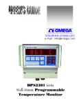
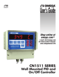
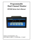
http://www.omega.com
e-mail: [email protected]
DPS3300 Series
wall mount Multi-Channel
Process Scanner
TABLE OF CONTENTS
SPECIFICATIONS ................................................................................................................................................................ 3
DESCRIPTION ...................................................................................................................................................................... 5
DISPLAYING PARAMETERS............................................................................................................................................. 6
Table 1. How to Display Parameters ................................................................................................................................. 6
DISPLAY MODES ............................................................................................................................................................ 7
Table 2. Display Modes..................................................................................................................................................... 7
Elapsed Time Mode............................................................................................................................................................ 7
Scan Mode.......................................................................................................................................................................... 8
High/Low Channel Mode ................................................................................................................................................... 8
Deviation Mode.................................................................................................................................................................. 9
Types of Deviation Displays .......................................................................................................................................... 9
Difference Mode................................................................................................................................................................. 9
SETUP.................................................................................................................................................................................... 9
'SYS' Parameter List......................................................................................................................................................... 10
CH Parameter List ............................................................................................................................................................ 10
CHANNEL CONFIGURATION ......................................................................................................................................... 11
Setup For Input Type.................................................................................................................................................... 11
Setup for Voltage or Current Input:.................................................................................................................................. 11
Setup For Channel ON/OFF ......................................................................................................................................... 11
Setup For Decimal Point Position ................................................................................................................................ 11
Setup For High Scale.................................................................................................................................................... 12
Setup For Low Scale .................................................................................................................................................... 12
Setup For Offset ........................................................................................................................................................... 12
Setup For Tare .............................................................................................................................................................. 12
Setup For Setpoint ........................................................................................................................................................ 13
Setup for Universal Relay (Channel 1 Relay) .............................................................................................................. 13
Setup For Limits ........................................................................................................................................................... 13
Setup For Deadband ..................................................................................................................................................... 13
Setup For Relay Normally Open/Closed ...................................................................................................................... 13
Setup For Engineering Units ........................................................................................................................................ 14
Setup for Thermocouple/ Thermistor/ RTD Inputs: ......................................................................................................... 14
Turning Channels ON/OFF: ......................................................................................................................................... 14
Temperature units:........................................................................................................................................................ 14
Setup Examples ................................................................................................................................................................ 15
Example #1: Use of the OFFSET Parameter ................................................................................................................ 15
Example #2: Use of the LOW SCALE Parameter........................................................................................................ 15
Example #3: Use of the TARE Parameter .................................................................................................................... 15
SYSTEM CONFIGURATION ............................................................................................................................................ 15
Setup For Display Options ............................................................................................................................................... 15
Table 3. Display Options............................................................................................................................................. 15
Setup For Display Time.................................................................................................................................................... 16
Setup For Relay Latch/Non-Latch.................................................................................................................................... 16
Relay Latched Mode: ................................................................................................................................................... 16
Relay Non-Latched Mode: ........................................................................................................................................... 16
Setup for Buzzer............................................................................................................................................................... 16
Setup For Cold Junction Calibration ................................................................................................................................ 16
Setup For Channel Calibration ......................................................................................................................................... 17
Input Range Setup (for current and voltage): ................................................................................................................... 17
Voltage Range Setup (0-10vdc, 0-5vdc) ...................................................................................................................... 17
Voltage Range Setup (for millivolt inputs) .................................................................................................................. 17
Current Range Setup..................................................................................................................................................... 17
Correct Range Settings ................................................................................................................................................. 17
Thermocouple Calibration Procedure............................................................................................................................... 17
SAVING PARAMETER:..................................................................................................................................................... 18
PEAKS ................................................................................................................................................................................. 18
PROGRAMMING FLOW CHARTS:.................................................................................................................................. 19
RATE ................................................................................................................................................................................... 22
LIMITS................................................................................................................................................................................. 22
OUTPUTS............................................................................................................................................................................ 22
Open Collector Option ..................................................................................................................................................... 22
Figure 1. Open Collector Hookup Example ................................................................................................................ 22
Page 1
TABLE OF CONTENTS
Electro-Mechanical Relay Option .................................................................................................................................... 22
Figure 2. Electro-mechanical Relays Hookup Example ............................................................................................... 22
FIG- 3. DPS3300 Series terminal compartment .................................................................................................................. 23
POWER................................................................................................................................................................................ 24
INPUT CONNECTOR PIN ASSIGNMENT....................................................................................................................... 24
Table 4. DPS3300 Series Output Connector Pin Assignments......................................................................................... 24
DIRECT INTERFACE TO UNIVERSAL RELAY MODULE........................................................................................... 25
TROUBLE SHOOTING ...................................................................................................................................................... 26
Factory Channel settings: ................................................................................................................................................. 26
Factory default settings for Thermocouple, voltage, current and milli-volt are: .............................................................. 26
ERROR MESSAGES AND SOLUTIONS .......................................................................................................................... 26
MOUNTING ........................................................................................................................................................................ 27
Figure - 4. Rear View And Mounting Hole Locations .................................................................................................... 27
WARRANTY....................................................................................................................................................................... 28
Page 2
SPECIFICATIONS
(Typical @ 25C and rated supply voltage unless otherwise specified)
STANDARD INPUTS
* 4-20ma 0-50ma 0-5Vdc 0-10Vdc
* Thermocouple inputs: J, K, T, E, R, S, and B
* Cold junction compensation error: +/- 1C (10C to 40C)
* Open input indication: HELP displayed
* Temperature displayable in Degrees C or F
* Non-standard inputs available --- consult factory.
ANALOG TO DIGITAL CONVERSION
* 4-1/2 Digit (20,000) Count) A/D Converter
* Dual slope integrating converter with 7 conversions /sec. (typical) rate.
SCAN RATE
* Fixed: two channels per second
DISPLAY
* Red seven segment displays--0.8" (20mm) digit height
* Over range indication: HELP
* Display test: Briefly displays 8.8.8.8.8.8.8 on power up.
* Seven-digit display
SCALE/OFFSET
* Scale programmable from 1 - 30000 units
* Offset programmable from 0 - 99.99mA (For mA Input)
* Offset programmable from 0 - 9.999V (For Voltage Input)
* Programmable decimal point.
RELIABILITY/ACCURACY
*Calibration: NIST traceable (for thermocouples)
*Temperature resolution: 1C/1F
* Warranty: 1 Year
* Recalibration recommended at 12-month interval
POWER REQUIREMENT
* 120Vac --- 60 HZ
* 240Vac --- 50 HZ
* 15VDC
(Standard)
(optional)
(optional)
OUTPUT (optional)
* Open collector outputs -- 50ma maximum sink, limited to 50ma per output
* Relays: Single pole single throw, 1 Amp @ 28Vdc or 0.5 Amp @ 120Vac resistive
*Output termination: Euro-style plug-in connector
Page 3
NOTE
DPS3304 & DPS3314 are four channel units. Therefore, any reference to channel numbers with
respect to these models is for channels 1 through 4 only.
DPS3307 and DPS3317 are seven channel units, and therefore, any reference to channel
numbers for these models is for channels 1 through 7.
DPS3304 & DPS3307 are base models that accept only one type of transducer signal on all
four/seven inputs.
DPS3314 & DPS3317 are enhanced models that have fully programmable inputs and each
channel can be configured independently to accept a low voltage signal (T/C, RTD, Thermistor,
milliVolt) or a voltage signal (0-5Vdc, 0-10Vdc) or a loop current signal (4-20mA, 0-50mA).
Page 4
DESCRIPTION
DPS3300 Series instruments are multi-channel scanners that pack a number of functions into one unit. Tasks that require
multiple monitors can now be accomplished by using only a single unit. Signals from a number of different transducers
can be brought into screw terminals that are conveniently located on the back panel of the instrument. The unit
automatically scans through each channel, displaying the channel number and process value. In addition to displaying
temperature, pressure, strain, etc. these units also boast some of the most frequently used functions such as process
differential between channels, monitoring high and low readings on individual channels, rate of change, tracking channels
with highest and lowest readings, comparison of process with a preset set-point, etc.
Signals from thermocouples are linearized and can be displayed in degrees Celsius or Fahrenheit. Transducers that put out
4-20 ma. current loop, 0-5Vdc, or other linear signals can be scaled from the front keys. This gives the flexibility of
displaying various parameters directly in engineering units. Channels that do not have signals connected to them may be
programmed off by the operator and will not be scanned or displayed.
On power up (check for proper power connections before powering up) the unit will first display 8.8.8.8.8.8.8. as a display
test and then the software revision number. The format is 'rEn x.xx' where x.xx is the revision level.
NOTE: Check model number for input type & display units -- thermocouples, 4-20ma, 0-10Vdc etc...
MODEL NO.
DPS3304 - (a) - (b) - (c)
DPS3314 - (a) - (b) - (c)
DPS3307 - (a) - (b) - (c)
DPS3317 - (a) - (b) - (c)
DESCRIPTION
4 Channel, fixed input scanner
4 Channel, programmable input scanner
7 Channel, fixed input scanner
7 Channel, programmable input scanner
(a)
INPUT TYPE
(a)
INPUT TYPE
TC
R
S
B
RTD
TH
P
J, K, T or E T /C
‘R’ thermocouple
‘S’ thermocouple
‘B’ thermocouple
RTD (385, 392)
Thermistor (400 Series)
100 millivolt
C
4-20ma current
(a)
INPUT TYPE
V
0-10 volt DC
(b)
POWER
(c)
OUTPUTS
5/3
6/4
Blank
4/7 Relay Outputs (optional)
4/7 Open Collector Outputs (optional)
No Output (standard)
Blank
1
2
120VAC Power Input (standard)
240VAC Power Input (optional)
15Vdc Power Input (optional)
Page 5
DISPLAYING PARAMETERS
DPS3300 Series keeps track of various parameters and these may be displayed by pushing appropriate keys on the front
panel. The parameters that are tracked are:
a) Channel's high peak
b) Channel's low peak
c) Elapsed time
c) Channel with the highest reading
d)
e)
f)
g)
Channel with the lowest reading
Process deviation of each channel from pre-programmed setpoint
Process differential of a channel with respect to any other channel
Rate of process change per minute for each channel
Table 1 explains how to display the above mentioned parameters.
Table 1. How to Display Parameters
TO DISPLAY
PERFORM FOLLOWING STEPS
1) Channel's high peak
a) Select channel whose high peak is desired (push CH SEL key)
b) Push HI/LO key once
2) Channel's low peak
a) Select channel whose low peak is desired (push CH SEL key)
b) Push HI/LO key twice --- 1st push displays high peak,
2nd push , low peak.
3) Rate of process change
a) Select channel whose Rate is desired (push CH SEL key)
b) Push DATA key once.
4) Channel deviation
a) Select desired channel (by pushing CH SEL key)
b) Push DATA key twice --- 1st push displays rate,
2nd push, deviation.
5) Channel differentials
a) Select desired channel (by pushing CH SEL key).
b) Push DATA key three times -- 1st push displays rate,
2nd push: deviation, 3rd push : differential.
c) Each additional push moves to the differential between selected
channel and the next channel.
d) e.g. the sequence for channel 1 is: RATE, CH1-SP, CH1-CH2,
CH1-CH3, CH1-CH4, CH1-CH5, CH1-CH6, CH1-CH7
6) Elapsed time
a) Push TIME key.
7) Channel with highest
process reading
a) Push HI/LO key once
8) Channel with lowest
process reading
a) Push HI/LO key twice ----1st push:
2nd push:
9) Scan
a) If the unit is holding, push the SCN/HLD key once.
10)Hold
a) If the unit is scanning, push the SCN/HLD key once.
high channel
low channel.
Page 6
DISPLAY MODES
DPS3300 Series has multiple display modes and can be programmed to either scan, display the channel with the highest
reading, display the channel with the lowest reading, deviation between channel's process variable and a pre-programmed
setpoint, difference between any two selected channels or just run as a timer. In the timer mode the unit keeps track of
process run time with crystal controlled accuracy. Elapsed Time display format is 'HH.MM.SS' for hours, minutes, and
seconds. The desired display mode is selected during SYS SETUP ---- (for details refer to the SYS CONFIGURATION
section).
Table 2. Display Modes
MODE
FUNCTION PERFORMED
1) Elapsed time
Unit displays elapsed time since power up or last time reset.
2) Scan
All active channels are automatically scanned.
Channels that are turned off are not scanned or displayed.
3) High Channel
The unit will compare all active channels against each other and
display the one that has the highest process reading.
4) Low Channel
The unit will compare all active channels against each other and
display the one that has the lowest process reading.
5) Deviation
The unit scans all active channels and displays the deviation of
process variable from a pre-programmed setpoint.
6) Channel Differential
The unit continuously displays the difference of process between
any two selected channels.
The following paragraphs give a detailed description and operation of various modes.
Elapsed Time Mode
DPS3300 Series can be programmed to run as timer. In this mode the unit will
indicate elapsed time in hours, minutes and seconds. The display format is
'HH.MM.SS'. This mode is selected during SYS Setup by opting for
'ELPSD t'. The elapsed time is the time passed since the unit was turned on or
when the time was last reset. To reset the time, first push the TIME key and
while keeping it pressed, push the RESET key. The display will show
'rESEt' and on release of the RESET key, the display will reset to '00.00.00'
and begin timing.
The elapsed time can also be momentarily displayed while the unit is
operating in any other display mode. This is done by pushing the TIME key
once. The unit will first display the word 'ELPSd t' followed by the elapsed time. This will stay in the display window for
a brief period and then the unit will revert to the normal display mode.
Page 7
Scan Mode
When setup for scan mode, individual channels are displayed for a programmed
period of time. At the end of that time period the, display automatically switches
to the next channel. For ease of reading, the display first shows the channel
number (Format: 'CHANEL 1') and then the process variable along with the
programmed three digit engineering units e.g. 23.45 PSI.
Display time for each channel is programmable from 1-999 seconds (16.65 min.).
This is useful for adjusting display time to a rate which is consistent with the type
of process being monitored. Scan time for each channel is independent of display
time. This permits programming long display times without losing track of the
process on other channels.
The display can also be put in a hold mode by pushing the SCN/HLD key. When this key is pushed, the display will
briefly show 'HOLd' after which the display will stop on the channel it was
indicating. Putting the unit in HOLD mode inhibits automatic display scanning
and shows only one particular channel. While the display is held on one channel,
internally all the enabled channels are continuously scanned for rate, difference,
limits and other parameters. Also, during HOLD mode the unit will periodically
flash the display 'Cx HOLd' ( x=channel # on hold) to indicate the status of the
display mode. If an attempt is made to hold on a channel that has been turned off
then the unit will indicate so by displaying in the format 'CHx OFF' (
x=channel # off).
To select another channel for display during hold mode, push the CH. SEL
key. Each push will increment the channel number. The display will first show
the channel number (e.g. 'CHANEL 2' for channel # 2) followed by the process
variable in the form '0.123 PSI'. When channel selection is initiated using the CH. SEL key, the unit starts with
channel #1 and steps thru to channel #7 with each push of the key.
To take the unit out of HOLD mode and back into SCAN mode, push the SCN/HLD key. The display will briefly show
'SCAN' and then start scanning the channels.
High/Low Channel Mode
DPS3300 Series compares all the channels against each other and constantly tracks
the channel with the highest and lowest process value. On push of a key, the
channel number and the value of process variable can be displayed. Also, during
SYS Setup, the unit can be programmed so that instead of scanning all the channels
it will only display the channel with highest or lowest process variable. As the
process changes, the display automatically switches over to the channel with the
highest (or lowest, if so programmed) reading. This is a very useful function for
applications involving multi-point monitoring of temperature in a single process.
For example, this feature can be used to find hot spots in a kiln. During high or low
channel scan mode the display will periodically flash 'HI CHAN' or 'LO CHAN' (depending upon the selected mode) to
indicate the status of the display mode.
To display high and low channel from any other display mode simply push the HI/LO key. Pushing this key once will
first display 'HI CHAN' and then the channel number and the process value will be displayed in the format 'C2 1234'.
The second push on the HI/LO key will first show 'LO CHAN' in the display window, and then the channel with the
lowest process value will be displayed.
NOTE: (i) The second push, to display low channel, must be initiated before the display reverts back to the normal
display mode.
(ii) If a channel is selected using the CH. SEL key prior to the push on the HI/LO key, then instead of
displaying high and low channels, the unit will display high and low peaks of the active channel.
Therefore, if it is desired to display high and low channels and not the peaks, do not select a channel
before pushing the HI/LO key.
Page 8
Deviation Mode
In deviation display mode, DPS3300 Series will show the differential between a pre-programmed setpoint and process
variable being monitored on each channel by the scanner. Individual setpoint for each channel is programmed during CH
Setup and can be any value over the range of selected scale or thermocouple being
used.
Types of Deviation Displays
There are two different ways of displaying channel deviation from their setpoint
values:
a) The first one is a momentary display in which the deviation is
indicated for a short time. Following this brief display time, the unit reverts to its
normal mode of operation (scanning, differential, timer etc.). To achieve this, first
select the channel whose setpoint deviation is desired. This is done by pushing the
CH. SEL key. Next, push the DATA key twice. The first push displays the
rate/minute value. The second push will display the deviation value. Before
showing the deviation, the display will read 'CH1 - SP' ( for CHannel 1 SetPoint).
b) The second method of displaying deviation is by selecting the 'dSP dEN' option when programming the
Display Option during the SYS Setup. If this method is selected, the display will scan through all the active channels and
display their deviation. The display format is 'd2 1234' (d stands for deviation).
The unit can also be put on HOLD at any channel by pushing the SCN/HLD key. If any other channel's deviation is
desired, it may be obtained by pushing the CH. SEL key. If an attempt is made to hold the display on a channel that has
been turned off, then the unit indicates this by displaying 'CHx OFF' (x=channel #). DPS3300 Series will keep track of
all other parameters while programmed for this mode (i.e. limits, peaks, rate, process value, channel differential etc). All
of these may be displayed by pushing the respective keys.
Difference Mode
In this mode the system continuously displays the difference of process variable
between any two selected channels. The two active channels are selected during
SYS Setup mode. To remind the operator of the current display mode and also
the two channels, the display flashes the channel numbers every few seconds
(e.g. 'CH1 - CH2' for displaying difference between channel #1 and channel #2).
If the unit is not programmed for difference mode, the differential between any
two of the seven channels can be briefly displayed by pressing the DATA key.
The procedure for doing so is to first select the channel whose differential with another channel is desired. This is done by
pushing CH SEL key. Each push on this key will display the selected channel in the format 'CHANEL x'(x=channel #).
When the desired channel has been selected, press the DATA key three times. The first push will display the rate of
process change on that channel. The second push will show the process deviation from the programmed setpoint. The third
push will flash a display of the form 'CH1 - CH2' and then a differential value. Additional pushes on DATA key will
sequence thru the channels and will be indicated as below:
CH1 - CH3, CH1 - CH4, CH1 - CH5, CH1 - CH6, CH1 - CH7, CH1 - SP
SETUP
Setup mode provides a means to customize the monitor to suit a particular
application. It allows programming such parameters as temperature units, limits,
display mode, relay deadband, etc.
SETUP mode has 2 sections:
a) SYS setup section to set system parameters
b) CH setup section to set Channel parameters for each channel.
Page 9
To get into SETUP mode, push the SETUP key twice. The first push displays elapsed time and the second push brings
the unit into the SETUP mode. SETUP mode is indicated by 'SETUP' in the display window (the SETUP LED indicator
will also be illuminated) followed by 'ENtR PC' (for ENteR PassCode). The passcode feature has been provided to
keep unauthorized personnel from changing any parameters. Each of the five keys on the front panel are labeled with a
number in the lower right corner. The pass-code is a four digit combination of these numbers. Enter the pass-code when
the displays reads 'ENTR PC' . Passcode for DPS3300 Series is 3254.
Once the correct pass-code has been entered, the display shows 'SYS CH', with 'CH' blinking. At this point the
operator may choose between making channel settings (CH), or system settings (SYS). Use SDIGT key to toggle
between CH and SYS modes. When the desired mode is blinking, press SETUP key to begin setup of parameters for that
mode.
'SYS' Parameter List
Following parameters can be setup when blinking 'SYS' is selected:
1) Display Options
3) Relay Latch/Non-latch
a) Elapsed Time
4) Calibration/Range setting
b) SCAN
a) Cold Junction Reference Temperature
c) High Channel
b) Thermocouple/voltage/current calibration
d) Low Channel
c) Voltage Range
e) Deviation
d) Current Range
f) Channel Difference
2) Display Elapsed Time
For more details, refer to the SYSTEM CONFIGURATION section.
CH Parameter List
Following parameters can be setup when blinking 'CH' is selected:
CURRENT OR VOLTAGE INPUT
THERMOCOUPLE, RTD, THERMISTOR INPUT
1) Select Channel
2) Input Type
3) Channel ON/OFF
4) Decimal Point Position
5) High Scale
6) Low Scale
7) Offset
8) Tare
9) Setpoint
10) Limit
11) Deadband
12) Relay Normally Open/Closed
13) Display Units
1) Select Channel
2) Input type
3) Channel ON/OFF
4) Temperature units (C or F)
5) Setpoint
6) Limit
7) Deadband
8) Relay normally open/closed
9) Engineering units
For more details, refer to the CHANNEL CONFIGURATION section.
Three attempts at entering correct pass-code are allowed. 'HELP' shows up in the
display window if attempted pass-code is wrong. If a person fails in three
attempts, the system will go back to normal display mode. To make another
attempt at this point one has to get into SETUP mode again.
Three keys are used during setup --- SETUP, WDIGX and SDIGT. If, at any
point during SETUP, it is desired to get out of SETUP and back to normal display
mode, push and hold the RESET key until the display reads 'SAVING'. The
SETUP key takes you from one parameter to the next e.g. if you are setting up
Channel ON/OFF, then after getting the desired value push SETUP key to setup
for Degrees C/F. WDIGX and SDIGT keys are used for programming values of
parameters such as limits, setpoints, etc.
Page 10
NOTE: To exit from any point during SETUP procedure or to save the newly made changes, simply press and hold the
RESET key until the display shows 'SAVING'. When the display shows 'SAVING', it is indicating that the unchanged and
the newly made changes are being saved in the EEPROM for permanent storage. It is important that the above step be
performed any time changes are made to the configuration of the unit and before power is removed. If not done so,
all the new changes will be lost. The unit will, however, maintain the old settings.
CHANNEL CONFIGURATION
After entering correct pass-code and selecting the blinking 'CH' (ref. SETUP section), the display shows 'SLCt CH' (for
"Select Channel"). Use SDIGT key to display the desired channel. Selected channel will be displayed in the format
'CHANEL x' (where x=channel#). Once the desired channel # is displayed, push SETUP key to go on to setup
parameters for the displayed channel #.
Setup For Input Type
The display will briefly show 'IP TYPE' (for "Input type") after which the
present input type for the selected channel will be displayed. Various inputs
available are: J T/C, CR.AL T/C (Chromel Alumel, type K T/C), T T/C, E
T/C, CURRENT, or VOLTAGE. If the unit has a noble metal thermocouple
option, then only one T/C can be selected i.e. B T/C, R T/C, or S T/C. Use the
SDIGT key to display the desired input type. Once the desired input type is
displayed, push the SETUP key to enter that input type and go to Setup For
Channel ON/OFF.
NOTE : If you have a millivolt input unit (instead of thermocouple), the various
types of inputs selectable are CURRENT, HI VOLT and LO VOLT (for millivolt input).
Setup for Voltage or Current Input:
Setup For Channel ON/OFF
After selecting input type, the next parameter for configuration is Channel
ON/OFF, which determines whether a channel is scanned or not. If for any reason
a channel is not being used, it must be turned OFF. In this way the unit will not
spend any time scanning it. This will also prevent the unit from displaying a
'HELP' message on a channel that has nothing hooked up to it. Use SDIGT key
to select the desired setting. If a channel is OFF, the display will show 'CHx
OFF' , and if the channel is ON the display will show 'CHx ON' (x=channel #).
Use SDIGT key to display the desired ON/OFF setting, and then push SETUP
key to enter that setting and go on to setup Decimal Point Position.
Setup For Decimal Point Position
After turning a channel ON or OFF, the next parameter for configuration is setting
the decimal point position. This is indicated by the display showing ' 9999' .
SDIGT key moves the decimal point through all the possible positions. After
'9.999', the display goes to '9999' which indicates a display with no decimal point.
Use SDIGT key to move the decimal point to the desired position, and then push
SETUP key to enter that setting and go to setup High Scale.
Page 11
Setup For High Scale
After setting a channel's decimal point position, the next parameter to be set is Hi
Scale. This parameter determines what number will be displayed when the
transducer puts out its maximum signal. For example, suppose a pressure
transducer produces a 0Vdc to 10Vdc signal which corresponds to 0psi to 150psi.
Then you would want the display to show 150 when 10Vdc is measured. To do
this, set the Hi Scale=150.
After pushing SETUP key, the display will briefly read 'HI SCLE' (for "High
Scale"), and then show the current High Scale setting. The flashing digit is the
active digit. Pushing SDIGT key and keeping it pushed, will increment the digit.
Releasing SDIGT key and then pushing it again will decrement the value
(SDIGT key works as a toggle -- alternating between increment and decrement). To change the next digit first push the
WDIGX key. This will advance the flashing to the following digit. Use SDIGT key to change the value. After the
desired High Scale setting is displayed, push SETUP key to enter that setting and go to setup Low Scale.
Setup For Low Scale
After setting a channel’s High Scale, the next parameter to be set is Low Scale.
This parameter determines what number will be displayed when the transducer
puts out its minimum signal. For example, suppose a pressure transducer produces
a 0Vdc to 5Vdc signal which corresponds to 10psi to 75psi. In this case the
display should read 10 when 0Vdc is measured. To do this, set the Lo Scale=10.
On pushing SETUP key, the display will briefly read 'LO SCLE' (for "Low
Scale"), and then show the present Low Scale setting. The flashing digit is the
active digit. Use SDIGT key (as described in Setup For High Scale) to change
the value. After the desired Low Scale setting is displayed, push SETUP key to
enter that setting and go on to setup Offset.
Setup For Offset
After setting a channel’s Low Scale, the next parameter to be set is channel offset.
Offset is used for calibrating a channel to a transducer that outputs a signal other
than zero at its low end. If a transducer happens to output a small signal at its low
end excitation, then the OFFSET parameter is used to make the transducer's
minimum signal appear to be zero e.g. if a flow transducer outputs a 0.130Vdc to
5.000Vdc signal which corresponds to a flow RATE of 0 to 40 gal./min. Then to
make the 0.130Vdc correspond to a display of 0, set OFFSET =0.130.
NOTE:
If the input type is CURRENT, the Offset value is entered in milliamps.
If the input type is VOLTAGE, the Offset value is entered in volts.
After pushing SETUP key at the completion of Setup For Low Scale, the display will briefly read 'OFFSEt', and then
show the present Offset value. The active digit will be flashing. Use the SDIGT key (as described in Setup For High
Scale) to enter a desired OFFSET value. After the desired OFFSET value is displayed, push SETUP key to go to Tare
setup.
Setup For Tare
After setting a channel’s OFFSET, the next parameter to be set is channel's TARE.
TARE is used if it is necessary to always subtract a value from a reading prior to
displaying that reading. For example, suppose a pressure transducer always
includes atmospheric pressure of 15 psi, and you only wish to display the pressure
differential from atmospheric (a gage reading of 19psi is to be displayed as 4psi).
To do this, enter the number you want subtracted from a measurement prior to
displaying the measurement.
The display will first show 'tARE' after which the current TARE value will be displayed. Use SDIGT key (ref. Setup
Page 12
For High Scale) to set the desired TARE number. Once the desired TARE value is displayed, push SETUP key to enter
that value and go to setup Setpoint.
Setup For Setpoint
After setting a channel's TARE, the next parameter to be set is channel's
SETPOINT. SETPOINT is used in Deviation Display mode. In this mode the
display is given as PROCESS-SETPOINT. For example, if it is desired to show
how Channel #1 temperature readings are varying from a target temperature of 212
degrees, then make the SETPOINT for channel #1=212.
When setting SETPOINT, the display will first show 'CHx SP', and then the
current SETPOINT value. Use SDIGT key (ref. Setup For High Scale) to get the
desired SETPOINT value. Once the desired SETPOINT value is displayed, push
SETUP key to enter that value and go on to setup channel 1's operational mode.
Setup for Universal Relay (Channel 1 Relay)
Channel 1 relay can be configured to work as a universal relay or as Channel 1
relay only. In universal mode, this relay gets activated whenever any channel on
the unit goes into alarm condition. In channel 1 mode, this output activates only if
process reading on channel 1 exceeds channel 1's programmed limit value. Display
format is
'C1 OnLY' (for 'Channel 1 only') or 'UnIVrSL' (for 'Universal').
Push SDIGT key to change to alternate mode and SETUP key after desired mode
is achieved.
Setup For Limits
After setting a channel's SETPOINT, the next parameter to be set is LIMIT. DPS3300 Series uses the LIMIT parameter
to determine when to activate output signal for a specific channel. When a reading exceeds the LIMIT for that channel,
then that channel's output signal is activated. When the channel reading drops below the LIMIT setting by the amount of
the DEADBAND setting, then the channel output is de-activated (if setup in non latching mode).
The display will first show 'CHx Lt' (x=channel #) after which the current LIMIT value will be displayed. Use SDIGT
key (ref. Setup For High Scale) to set the desired LIMIT value. Once the desired LIMIT value is displayed, push SETUP
key to enter that value and go on to setup Deadband.
Setup For Deadband
After setting a channel's LIMIT, the next parameter to be set is channel's relay
DEADBAND. This parameter is used for eliminating relay "chatter" as a signal
hovers around its LIMIT value. When the channel reading drops below the LIMIT
setting by an amount equal to the DEADBAND, then the channel output is deactivated. Minimum value of DEADBAND is 2.
The display will first show 'dEAd bd' after which present DEADBAND value
will be displayed. Use SDIGT key (ref. Setup For High Scale) to set the desired
DEADBAND value. Once the desired DEADBAND value is displayed, push
SETUP key to enter that value and go on to setup Relay as Normally Open/Closed.
Setup For Relay Normally Open/Closed
After setting DEADBAND, the next parameter determines whether the channel's output relay operates as a "Normally
Open" or "Normally Closed" style relay. The relay itself is a Single Pole Single Throw (SPST) relay.
Page 13
When this parameter is set for "Normally Open", the relay is open when it is deactivated (readings are below LIMIT), and
closes when the channel reading exceeds its LIMIT value. When this parameter is set for "Normally Closed", the relay is
closed when it is deactivated (readings are below LIMIT), and open when
channel reading exceeds LIMIT value.
The display will show 'rLy N.O.' for relay Normally Open or 'rLy N.C.'
for Normally Closed setting. Use SDIGT key to toggle between the two
settings. Once the desired setting is displayed, push SETUP key to enter that
value and go on to setting up Engineering Units.
Setup For Engineering Units
After setting a channel's relay for NORMALLY OPEN/CLOSED operation,
the next parameter to be set are the 3 letters that follow the process value in the display. These 3 letters represent the
measurement units for that particular channel. Any desired combination of the following letters may be programmed:
A,B,C,D,E,F,G,H,I,J,L,N,O,P,Q,R,S,T,U,Y
The letter selection goes up to 'Y' and down to 'A' and from 'A' down to ' - '
sign. The ' -' sign indicates that the particular digit will be blanked e.g. if the
desired engineering unit was feet, then the display can be programmed to show '
Ft'. In this case one digit will be blanked out by programming a ' - ' sign in its
location.
Three dots are displayed if no engineering units are programmed for a channel.
Whenever the input type is changed from one type to another, the system
automatically clears the engineering units. Therefore, it is necessary to re-enter
new units after a change in the input type has been made. The only exception in
this case is when a thermocouple selection is made. In that case, the unit automatically enters an 'F' or 'C' (Fahrenheit or
Centigrade) depending upon the selected display units. However, just like the other inputs, any alternate units may be
programmed for thermocouples.
The display will first show 'Cx UNIt' (x=channel #) after which the current UNITS will be displayed. Use SDIGT key
(ref. Setup For High Scale) to setup desired UNITS. Once the desired UNITS are displayed, push SETUP key to enter
them and then go back to 'SYS CH' display.
Setup for Thermocouple/ Thermistor/ RTD Inputs:
Turning Channels ON/OFF:
If selected option under 'IP tYPE' is thermocouple, RTD or thermistor, then the next step is turning the channel ON or
OFF. This is done by pushing SDIGT key. Once the desired selection has been made, push SETUP key to go to the
next step.
Temperature units:
This step configures the display units to Centigrade or Fahrenheit for the
selected input. The display either shows "dEGrE C" or "dEGrE F"
depending on previously selected units. Use SDIGT key to select alternate
mode. Once having obtained the desired units, press SETUP key to go on to
the next parameter. The following steps (i.e. channel setpoint, Channel limit,
relay dead-band and engineering units) are the same as for voltage and current
inputs -- refer to appropriate sections and/or flow chart.
Page 14
Setup Examples
Example #1: Use of the OFFSET Parameter
Setup for a 4-20ma transducer signal corresponding to 0-500 gallons of fluid (reading in 10th of a gallon resolution):
DECIMAL POINT
HIGH SCALE
LOW SCALE
OFFSET
TARE
= 999.9
= 500.0
= 000.0
= 4.000
= 0.000
Example #2: Use of the LOW SCALE Parameter
Setup for a 4-20ma transducer signal corresponding to 500-2000 degrees Fahrenheit temperature i.e. 500 degrees at 4ma
and 2000 degrees at 20ma (one degree resolution):
DECIMAL POINT
HIGH SCALE
LOW SCALE
OFFSET
TARE
= 9999
= 2000
= 500
= 4.00
= 0.000
Example #3: Use of the TARE Parameter
Setup for a 0-5Vdc transducer signal corresponding to 0-10.00 pounds of material being packaged in a box weighing 0.50
pounds with display reading in 0.01 lb. increments. DSP3200 should display the weight of the material only (not the box
as well):
DECIMAL POINT
HIGH SCALE
LOW SCALE
OFFSET
TARE
= 99.99
= 10.00
= 00.00
= 0.00
= 0.50
SYSTEM CONFIGURATION
After entering the correct pass-code and selecting the blinking 'SYS' (ref. SETUP section), DPS3300 Series goes into
SYSTEM CONFIGURATION mode. This mode allows setting up parameters
that affect all the channels or the instrument in general.
Setup For Display Options
After pushing SETUP key while SYS is blinking, the display briefly shows
'dSP OPt' (for display option) and then the present Display Option setting.
Table 3 below lists all 6 display options available. Use SDIGT key to step
thru the options. Once the desired Display Option is shown, push SETUP key
to enter the setting and go to Setup For Display Time.
Table 3. Display Options
DISPLAY OPTION
1) Display elapsed time
2) Scan active channels
3) Display channel with highest reading
4) Display channel with lowest reading
5) Display deviation from SETPOINT
6) Display channel differential
DISPLAY WINDOW READS
ELPSEd t
SCAn
HI CHAN
LO CHAN
dSP dEN
CH1 dIF
Page 15
The channel numbers in Display Option #6 start with 'CH1 dIF' and go up to 'CH7 dIF' (CH4 dIF for 4 channel units).
Following this the display jumps back to Option #1 (elapsed time), and the cycle is repeated.
Setup For Display Time
The next parameter to be set is DISPLAY TIME. This determines the number
of seconds a channel's reading is displayed before moving to the next channel.
The display will first show 'dSPLy t' (for Display Time), and then the current
setting in seconds. Use SDIGT key (ref. Setup For High Scale) to set the
desired DISPLAY TIME. Once the desired DISPLAY TIME value is displayed,
push SETUP key to enter that value and go to setup Relay as Latching or NonLatching.
Setup For Relay Latch/Non-Latch
After setting DISPLAY TIME, the next parameter determines whether the output relays will operate in a Latched or NonLatched mode.
Relay Latched Mode:
In this mode the relay is activated when its LIMIT value is exceeded and stays
activated until the operator manually resets the relay. To manually reset a
channel relay, use CH. SEL key to step to the desired channel number, and while
keeping the CH. SEL key pressed, simultaneously press the RESET key.
Relay Non-Latched Mode:
In this mode the relay is activated when its LIMIT value is exceeded. The relay
is deactivated when the channel reading drops below the LIMIT value by the
DEADBAND setting.
The display will show 'NON LCH' for Non-Latch mode, or 'LAtCH' for Latch mode. Use SDIGT key to toggle
between settings. Once the desired setting is displayed, push SETUP key to enter that value and go to Setup For Cold
Junction Calibration.
Setup for Buzzer
The next step turns the buzzer on or off. Turning on the buzzer provides an audio
alarm whenever any limit gets activated. Display format is 'ALr On' (for 'alarm
on') or 'ALr OFF' (for 'alarm off'). Push SDIGT key to select desired mode.
After completing the selection, push SETUP key to go to next step.
Setup For Cold Junction Calibration
After setting Relay Latch/Non-Latch, the next parameter is the cold junction
reference temperature. The display will first show 'COLd JN' , and then the
cold junction temperature will be indicated. Use the SDIGT key to adjust until
the display reads the proper temperature. Once the correct temperature is
displayed, push the SETUP key to enter that setting and go to Setup For Channel
Calibration.
NOTE 1: The unit must be powered up for at least ten minutes before
adjustments are made to cold junction reading.
NOTE 2: Press CH. SEL key to see the Cold Junction reading directly in
millivolts.
Page 16
Setup For Channel Calibration
After setting the Cold Junction Reference temperature, the next step is a display of channels for calibration purposes. This
allows easy calibration of each channel without the instrument scanning to the next channel. The display will show the
channel input reading in the form 'x-nnnnn' where x=channel # and nnnnn is the channel reading.
NOTE: ONLY channels that are turned ON will be displayed at this time!
Press SETUP key to step the display to the next channel.
Input Range Setup (for current and voltage):
Voltage Range Setup (0-10vdc, 0-5vdc)
After all the enabled channels have been displayed, the VOLTAGE range may
be setup. The display will briefly show 'U rAnGE' (for "Voltage Range")
followed by the current setting. Use SDIGT key (ref. Setup For High Scale)
to set the desired VOLTAGE value. Once the desired value is displayed, push
SETUP key to enter that value and go to the next step.
Voltage Range Setup (for millivolt inputs)
For Millivolt input units, the display first shows 'HV rnGE' (for "High Voltage Range"). After the High Voltage range
is set, the display shows 'LV rnGE' (for "Low Voltage Range"). Enter values for respective inputs.
Current Range Setup
After VOLTAGE range has been set, the CURRENT range may be set. The
display will briefly show 'C RANGE' (for "Current Range") followed by the
current setting. Use SDIGT key (ref. Setup For High Scale) to set the desired
CURRENT value. Once the correct CURRENT range is displayed, push SETUP
key to enter that value and return to 'SYS CH' display.
Correct Range Settings
The following RANGE values should be entered for various inputs:
RANGE VALUE
INPUT
0-5 Vdc
5.000
0-10 Vdc
10.000
0-100 Mv
100.0
4-20 Ma. (loop current)
20.00
Thermocouple Calibration Procedure
Note: Make sure the unit is reading correct cold-junction temperature before calibrating.
If incorrect, adjust as described in the "Setup For Cold Junction" section.
For a thermocouple channel calibration (type J T.C), following steps should be performed. Note that calibrating any
channel automatically sets the calibration for all channels. Also, only one type of thermocouple input needs to be
calibrated i.e. J,K,T or E. For example, if the calibration is done for a type K thermocouple, types J, T, and E are
automatically calibrated.
1. Connect a thermocouple calibration source to channel 1.
2. Dial in 1100 degrees centigrade (Note: unit must be programmed for displaying in centigrade).
Page 17
3. Adjust the gain pot of the instrument until the display reads '1100'.
4. Short channel #1's input with a wire or shorting bar.
5. Push DIFF key. The display will read '0002' --- or some other value.
6. Adjust offset pot of instrument until the display reads '0000'.
7. Push SETUP key -- the display will show Cold Junction temperature.
8. Remove the shorting bar from channel one input and connect the thermocouple calibrator again.
9. Repeat steps 2 through 7 till the unit reads proper temperature.
1
4
1: GAIN POT (T/C, MV, RTD, TH)
2: OFFSET POT
3: VOLTAGE POT
4: CURRENT POT
SAVING PARAMETER:
DPS3300 series saves all the programmed parameters in an EEPROM (electrically erasable programmable read only
memory). An EEPROM stores the parameters even when power is removed from the unit. However, it is important to note
that if the parameters are changed during setup, they must be saved in the EEPROM by pressing reset key as described
under setup. If the parameters are not saved and the power is removed from the unit, any newly changed values will be
lost (the unit will, however, maintain the old values).
PEAKS
A very useful function of DPS3300 is tracking the highest (peak) and the lowest
(valley) point attained by each channel. This is particularly helpful if an operation
is not being constantly watched or is left unattended (e.g. overnight). Since high
and low points for each channel are monitored and stored separately, the history of
changes at various points in the process can be obtained. This can be useful for
quality control or for finding properties of a certain process.
The first step in displaying peaks is to select the channel whose peaks are desired.
This is done by pushing the 'CH. SEL' key. Each time this key is pushed, the
display indicates the selected channel e.g. CHANEL 2, CHANEL 3 and so on.
Page 18
Once the desired channel has been selected, push 'HI/LO' key. Pushing it once will show the high peak attained by the
selected channel. Pushing it a second time will indicate the low process value (NOTE: The second push, to display valley,
must be initiated before the display reverts to normal display mode). Before
displaying high peak, the display will read 'CH2 HI' (for Channel 2 High Peak).
Similarly, for low peak the display will indicate 'CH2 LO' (for Channel2 Low
Peak) before showing the value.
If an attempt is made to display the high or low peak of a channel which has been
turned off (in CH Setup), the display will read 'CHx OFF' (x=channel #) to
indicate the channel status.
Peaks can be reset to the present value of process (e.g. if channel 1 is reading 200
C, its peaks can be reset to 200). This will allow tracking the process from
present temperature being read by the unit. To reset high peak, first select the
channel whose peak is desired to be reset (by pushing the CH. SEL key). Once the channel has been selected, push
HI/LO key and keep it pushed. The display will read 'HI P' following which the value of high peak will be displayed.
With HI/LO key still pushed, go on to push the RESET key. The display will read 'RESEt' and the unit will then take the
present value of process on that channel and enter it as new high peak. To reset low peak, release HI/LO key (from high
peak display mode) and push it again immediately -- and keep it pushed. The display will read 'LO P' and then the value
of channel's low peak. With HI/LO key still pushed, press the RESET key. The display will read 'RESEt' and the unit
will enter present process value as the channel's new low peak.
PROGRAMMING FLOW CHARTS:
FOLLOWING PAGES SHOW FLOW CHARTS FOR DPS3300
UNITS:
Page 19
DPS3317
7 Channel Unit
DPS3314
4 Channel Unit
ENTER PASSCODE -- 3254
‘SYS’ Flashing
SYS CH
‘CH’ Flashing
SELECT CHANNEL
DISPLAY OPTION (Select one)
ELAPSED TIME
SCAN
HIGH CHANNEL
LOW CHANNEL
DISPLAY DEVN.
CHANNEL DIFF.
-TH Option
HI VOLTAGE
CURRENT
THERMISTOR
DISPLAY TIME
IP TYPE
-BM Option
R, S or B Option
-100mv Option
LO VOLTAGE
HI VOLTAGE
CURRENT
-RTD Option
HI VOLTAGE
CURRENT
RTD 385
RTD 392
VOLTAGE or CURRENT CHS.
HI VOLTAGE
CURRENT
R, S or B T/C
(only one T/C
option)
HI VOLTAGE
CURRENT
‘J’ T/C
CR.AL T/C (K)
‘T’ T/C
‘E’ T/C
TEMPERATURE CHS.
CH ON/OFF
RELAY LATCH/NON-LATCH
CH ON/OFF
DECIMAL POINT
AUDIO ALARM ON/OFF
HIGH SCALE
DEGREE C/F
LOW SCALE
COLD JUNCTION
OFFSET
CH. CALIBRATION
TARE
CH ‘X’ SETPOINT
VOLTAGE RANGE
CH1 RELAY/UNIVERSAL RELAY
CURRENT RANGE
‘X’ stands for Channel No.
CH ‘X’ LIMIT
RELAY DEADBAND
Back to ‘SYS CH’
RELAY NO/NC
ENGINEERING UNIT
Page 20
DPS3307
7 Channel Unit
DPS3304
4 Channel Unit
ENTER PASSCODE -- 3254
‘SYS’ Flashing
DISPLAY OPTION (Select one)
ELAPSED TIME
SCAN
HIGH CHANNEL
LOW CHANNEL
DISPLAY DEVN.
CHANNEL DIFF.
-TH Option
SYS CH
‘CH’ Flashing
SELECT CHANNEL
IP TYPE
R, S or B Options
mV, V or C Options
‘R’ T/C
HI VOLTAGE
THERMISTOR
RTD 385
RTD 392
CURRENT
DISPLAY TIME
-BM Option
-RTD Option
LO VOLTAGE
VOLTAGE or CURRENT CHS.
‘S’ T/C
‘B’ T/C
‘J’ T/C
CR.AL T/C (K)
‘T’ T/C
‘E’ T/C
TEMPERATURE CHS.
CH ON/OFF
RELAY LATCH/NON-LATCH
CH ON/OFF
DECIMAL POINT
AUDIO ALARM ON/OFF
HIGH SCALE
DEGREE C/F
LOW SCALE
COLD JUNCTION
OFFSET
CH. CALIBRATION
TARE
CH ‘X’ SETPOINT
VOLTAGE RANGE
CH1 RELAY/UNIVERSAL RELAY
CURRENT RANGE
‘X’ stands for Channel No.
CH ‘X’ LIMIT
RELAY DEADBAND
Back to ‘SYS CH’
RELAY NO/NC
ENGINEERING UNIT
Page 21
RATE
DPS3300 series tracks the rate of process change/minute for each channel. This
rate is displayed by first pushing the CH. SEL key to select the channel whose rate
is desired. Once the channel has been selected, push DATA key. The display will
briefly read 'cx-rate' (x=channel #), and then the monitored rate for that channel.
LIMITS
DPS3300 series units support limit alarms on all the channels. These limits can be
programmed over the entire range of selected thermocouple or scale. Thus, not only
can these units be used as monitors but they can also provide control capability on
each channel. Limit values are programmed during CH Setup. Also programmed during CH Setup is the dead-band
(hysteresis) value. This keeps the relays from chattering when the process is hovering just around the limit.
OUTPUTS
DPS3300 Series units can be ordered with either open collector outputs or electro-mechanical relays. Check model
number printed on the unit.
Open Collector Option
Whenever a limit is reached an open collector output provides a 5 Vdc signal at 50ma. on the output connector, eg.. Limit
#4 provides its 5 volt output signal between pins 7 & 8 of the card edge.
Figure 1. Open Collector Hookup Example
Instrument
+5VDC
+ OUTPUT
7
LOAD
- OUTPUT
8
Solid Sate Relay
LED, Buzzer, ETC.
Electro-Mechanical Relay Option
These relays are programmed during CH Setup to operate as either Normally Open (NO) or Normally Closed (NC). The
default setting is Normally Open. Each of these limit relays provides a switched output whenever a limit is reached. The
maximum rating for a 120Vac unit is 120Vac @ 0.5 amp or 28 Vdc @ 1.0 amp. A 240Vac unit is rated at 240Vac @ 0.25
amp. or 28Vdc @ 1.0 amp.
Figure 2. Electro-mechanical Relays Hookup Example
PLUG-IN CONNECTOR
8
Limit # 4
7
120 VAC @ 0.5 AMPS
5
120 VAC @ 0.5 AMPS
6
Limit # 3
Instrument
Switched Outputs
4
Limit # 2
Limit # 1
3
120 VAC @ 0.5 AMPS
2
1
120 VAC @ 0.5 AMPS
Page 22
NOTE:
LOOK UNDER SPECIFICATIONS FOR THE RATING ON RELAYS AND OPEN COLLECTOR
OUTPUTS. UNDER NO CONDITION SHOULD THE RELAYS AND OPEN COLLECTOR
OUTPUTS BE OPERATED BEYOND THEIR RATED CAPACITY. DOING SO CAN DAMAGE
THE UNIT PERMANENTLY.
The status of the relays for all the channels is indicated on the front panel by a row of LEDs. Whenever the relay is
energized, its respective LED is turned on.
FIG- 3. DPS3300 Series TERMINAL COMPARTMENT
OUTPUT CONNECTOR
INPUT CONNECTOR
L1
Pin 1
Pin 1
Pin 14
Pin 14
GND
L2
POWER INPUT
CONNECTOR
Page 23
POWER
Power connection should be made to the three terminal connector as shown in figure 3. Also, make note that it is very
important that the power line inputs and the power ground are not switched. Doing so will permanently damage the
instrument. Refer to Figure 3 for proper connections. For convenience, the printed circuit board is labeled
L1 L2 GND on the under side of three terminal power connector. For instruments with the 15Vdc power option,
L1 = negative supply and L2 = positive supply.
NOTE: WHILE CONNECTING POWER TO THE UNIT, MAKE SURE THAT AC POWER LINE L1 OR
L2 IS NOT ACCIDENTALLY CONNECTED TO GROUND (GND) TERMINAL. THIS WILL RESULT IN
PERMANENT DAMAGE TO THE INSTRUMENT.
DOUBLE CHECK THE CONNECTIONS BEFORE APPLYING POWER!!
INPUT CONNECTOR PIN ASSIGNMENT
1
2
3
4
5
6
7
8
9
10
11
12
13
14
CH1 - CH1+ CH2 - CH2 + CH3 - CH3 + CH4 - CH4 + CH5 - CH5 + CH6 - CH6 + CH7 - CH7 +
Table 4. DPS3300 Series Output Connector Pin Assignments
OUT-PUT CONNECTOR PIN ASSIGNMENTS
Pin #
1
2
3
4
5
6
7
8
9
10
11
12
13
14
Signal
Channel #1 Limit
Channel #1 Limit
Channel #2 Limit
Channel #2 Limit
Channel #3 Limit
Channel #3 Limit
Channel #4 Limit
Channel #4Limit
Channel #5 Limit
Channel #5 Limit
Channel #6 Limit
Channel #6 Limit
Channel #7 Limit
Channel #7 Limit
Relay Output
Common
Normally Open/Closed*
Common
Normally Open /Closed*
Common
Normally Open/Closed*
Common
Normally Open/Closed*
Common
Normally Open/Closed*
Common
Normally Open/Closed*
Common
Normally Open/Closed*
Open Collector
Positive Output
Negative Output
Positive Output
Negative Output
Positive Output
Negative Output
Positive Output
Negative Output
Positive Output
Negative Output
Positive Output
Negative Output
Positive Output
Negative Output
* = Normally Open/Closed is user programmable (Look under Set-up)
NOTE: PROPER RATING, CONNECTION AND CORRECT ORIENTATION OF THE CONNECTOR IS
NECESSARY TO AVOID MALFUNCTION OR PERMANENT DAMAGE TO THE UNIT.
Page 24
DIRECT INTERFACE TO UNIVERSAL RELAY MODULE
A special feature in the DPS3300 series units allows direct interfacing with Universal Relay Module (Model RELAYURM400/800) – via a serial interface. The serial interface is available at a separate connector (as shown) in the terminal
compartment.
RELAY-URM400/800 series relay module is a very versatile instrument that is used for switching up to eight 15 ampere
loads. In addition to the DPS3300 serial interface, RELAY-URM400/800 series relay module accepts low level input
signals from PLCs, process controllers, indicators, motor starters, etc. Selectable input allows activation of output relays
on direct acting or reverse acting signal. In addition to working with control/logic level signals, another very useful feature
of RELAY-URM400/800 is activation of output relays on contact closure. The use of the RELAY-URM400/800 allows
heavy loads requiring up to 15 amps to be controlled by the DPS3300 with minimal equipment & wiring.
Input and output connections for the RELAY-URM400/800 are made through euro style pluggable connectors which are
conveniently located on the top and bottom of the unit. Screw in terminals allow for quick connect/disconnect of wires.
The unit is housed in a versatile enclosure that can be configured for mounting on a DIN rail or on a wall. If desired, the
same enclosure can be panel mounted with relay, AC and DC supply status visible on the front. LEDs on the front panel
turn on when a relay is energized. Two different versions are offered in this series. First one is RELAY-URM400 that has
four relay outputs. The second one is RELAY-URM800 that has eight relay outputs. (Future versions will also include 415A solid state relays). Both units come with a built-in universal power supply. It operates from 100vac to 240vac. This
power supply provides power not only to the internal electronics and relays but has up to 20watts (5, 12 or 24vdc)
available for external applications by the user.
DIRECT SERIAL
INTERFACE TO
RELAY-URM400/800
DPS3300 TERMINAL COMPARTMENT
SERIAL PORT
FOR RELAY-URM400/800
Page 25
TROUBLE SHOOTING
If the meter locks on a particular display, unplug and plug in again to unlock the display. A total reset clears the memory
and defaults all values to zero. To perform this reset, re-apply power with RESET key pressed in.
Factory Channel settings:
To obtain factory preset values simply re-apply power with SDIGT key pressed in. This will also clear memory of any
erroneous values and is the preferred method of resetting a unit that might be malfunctioning due to corrupted memory .
Factory default settings for Thermocouple, voltage, current and milli-volt are:
PARAMETER
HIGH SCALE
LOW SCALE
OFFSET
TARE
CURRENT
INPUT
20.000
0.000
0.00
0.000
VOLTAGE.
INPUT
10.000
0.000
0.00
0.000
MILLIVOLT
INPUT
T/C
INPUT
100.00
0.000
0.00
0.000
J
J
J
J
ERROR MESSAGES AND SOLUTIONS
ERROR MESSAGES AND SOLUTIONS
ERROR MESSAGE
ERROR CONDITION
SOLUTION
'EE EROR'
The unit was unable to
save programmed value
in EEPROM -- possible
failure of EEPROM.
If the message keeps coming up,
unplug the unit and reapply power.
If the unit still displays the error
message, send it in for repair.
If error message followed by
8.8.8.8.8.8.8.and the revision
number are displayed occasionally,
it is an indication that power
line is very noisy and needs a line filter.
'CARD ER'
Too much noise on
input signals or problem
with Scanner card.
1. If message shows occasionally,
it indicates that input signal s have
too much high voltage noise.
Provide signal filters.
2. Unplug and plug the meter again
to recycle power.
3. Scanner card defective -- send in
for repair
'HIGH AC NOISE'
High AC noise on input
signals or incoming AC
line interfering with the
operation of the unit
1. If message shows occasionally,
it indicates that input signals or
AC line has too much high
voltage noise.
2. Provide line and signal filters.
Page 26
MOUNTING
PICTURE HANGING-TYPE
FIXTURE FOR MOUNTING SCREW
120mm
4.72”
MOUNTING SCREW SLOTS
151mm
5.94”
Figure - 4. Rear View And Mounting Hole Locations
SLOTS IN TERMINAL COMPARTMENT
FOR MOUNTING SCREWS
Page 27
WARRANTY
Page 28
Page 29
M4302/0306
Page 30