1
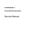
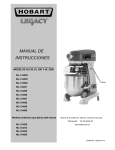
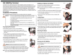
USING THE RPS-1in the OM-420
USING THE RPS-1, RECHARGEABLE POWER SUPPLY
IN THE OM-420
OVERVIEW:
The RPS-1 is a self-contained battery power source for use in conjunction with the OM-320/420 System
Base to power transducers requiring external power (e.g. Strain Gages, Pressure transducers, 4 to 20ma
Loop Transmitters, etc.) over a voltage range from 3.5 to 22 VDC.
The RPS-1 contains two User-configurable, rechargeable gel-cell type batteries and integral recharging
circuitry. The charging circuitry will accept AC or DC current from Photovoltaic arrays, wind generators,
utility sourced transformers/plug-in power supplies, or other current sources. The sealed batteries are
capable of operating in any orientation and over a temperature range of -10 to 60C. A slide switch allows
the User to configure the RPS-1 for 12 or 24VDC operation.
Two User-programmable Power Supply outputs are available which can source 7 different regulated
voltage levels from 3.5VDC to 22VDC. Outputs are short circuit / over-current protected.
The two Power Supplies can be independently programmed for output voltage as well as type of
operational mode. Two modes are available, Continuous ON or AUTOMATIC Operation. In AUTOMATIC
Operation, the power supply is under control of an optically isolated low voltage (5VDC, 0.5mA) control
input signal. This control INPUT interfaces directly to a OM-320/420 Digital Output line which can be
programmed to cycle the RPS-1 power supplies ON and OFF, providing transducer excitation under OM320/420 control during a logging session. This automatic power supply cycling technique maximizes RPS1 battery life. See Figure 1 for a sample Hypernet
Figure 1: RPS-1 Control Using HyperWare Warm-Up
Icon
Omega Engineering Inc.
1
Stamford, CT
USING THE RPS-1in the OM-420
An integral State-of-Charge (SOC) indicator is provided which will display an approximate Battery State-ofCharge based on battery voltage under a fixed load. Test is actuated by depressing a momentary SOC
Test Switch.
HARDWARE / USER CONTROLS:
Figure 1 illustrates the functional blocks contained within the RPS-1. An explanation of each block follows:
MAIN POWER SWITCH
Provides ON/OFF control of the RPS-1. In the OFF position, the batteries are disconnected from the RPS1 circuits (power supplies, State-of-Charge indicator, charging circuits, etc.). This switch in either 12 VDC
or 24 VDC ON position selects how the two 12 volt gel-cell batteries are connected (parallel for 12 VDC
nominal output or series for 24 VDC nominal output). Note: For charging, the Main Power switch must be in
either the 12VDC or 24VDC position.
Battery State of
Charge light bar
External Power
Supply Control
Signal
Main Power
Switch
Power Supply
A
+
Power Supply
B
+
12 V Gel-Cell
BATTERY
12 V Gel-Cell
BATTERY
Battery Charging
circuitry
-
-
hl200-01.ecw
Figure 2: RPS-1 Functional Block Diagram
CHARGER INPUT
Two terminal connections are provided for connection of an external current source for charging the RPS-1
batteries.
POWER SUPPLY OUTPUTS
Two independent User programmable voltage power supply outputs (A and B) feed the twelve position
terminal strip on the right side of the unit. The top four terminals are all connected to the A supply output
and the middle four to the B supply output. The bottom four terminals are all connected together and to
the COMMON (circuit ground) of the two supplies.
OUTPUT VOLTAGE / MODE SWITCHES
Each of the two power supplies has an eight position DIP switch associated with it. The top seven switches
determine the output voltage for that supply and the last switch (#8) defines the mode of operation (AUTO
or ON) for the power supply.
Omega Engineering Inc.
2
Stamford, CT
USING THE RPS-1in the OM-420
CONTROL INPUT
Two terminal connections are provided for connection of a low voltage power supply control signal. This
input signal controls the ON/OFF cycling of power supplies set to the AUTO mode. Typically, this control
input is controlled by a OM-320/420 Digital Output.
STATE-OF-CHARGE INDICATOR
When the TEST button is depressed, an approximate battery state of charge is displayed on the 10
position Display. This display is based on the battery voltage under a slight load.
INSTALLATION
MOUNTING
The RPS-1 should be mounted in a vertical position in order to optimize rain shedding and prevent direct
spray into the bottom fittings. The enclosure is designed for indoor and outdoor exposure within the
specified temperature limits. Battery life and capacity is at a maximum when the batteries are at a
temperature of 20C (68F). Shading from direct sunlight and/or insulation WITHOUT RESTRICTING AIR
FLOW AROUND THE UNIT can optimize battery life and capacity. During charging, the batteries will emit
small amounts of FLAMMABLE AND EXPLOSIVE HYDROGEN GAS. Additionally, heat is generated by
the voltage regulating circuits. For these two reasons, ventilation around the package will maximize
performance as well as minimize risk of potentially hazardous explosions.
WIRING
The OM-420 is factory configured to use OM-320/420 Digital Output #1 to control the RPS-1.
These connections are as follows: The positive Digital Output (Marked D01 on the TSA) is
connected to the RPS-1 positive CONTROL INPUT terminal.
The negative Digital Output (Marked GND on the TSA) is connected to the RPS-1 negative
CONTROL INPUT terminal. (See Figure 2)
Power Supply wiring should be routed through the liquid-tite fittings in the bottom of the OM-420 enclosure.
For most applications, 18 AWG wire will suffice without excessive voltage drop (18 AWG will result in less
than 0.1 V drop in 100 feet at 150 mA). PVC jacketed multi-conductor wire is a good choice that seals well
in the liquid-tite fittings.
OPERATION / SET-UP
POWER SUPPLIES
Select the desired output voltage for the A and B power supplies from the following table:
1 = 22 VDC
2 = 18 VDC
3 = 15 VDC
4 = 12 VDC
5 = 10 VDC
6 = 5 VDC
7 = 3.5 VDC
Set ONE of the seven VOLTAGE PROGRAMMING switches to the desired choice on each supply. If a
supply is not utilized, set all switches OFF (to the left). Correct voltage setting can be verified with a volt
meter reading from the OUTPUT terminal to the COMMON terminal. ONLY ONE voltage programming
switch should be ON for each supply.
Omega Engineering Inc.
3
Stamford, CT
USING THE RPS-1in the OM-420
Battery State of Charge
Indication
RPS-1 Power
4-20mA transmitter
output
to Port 1, Chan
B
4-20mA
Xmtr
Power
Supply
Output
5VDC Powered
Transducer
(mV Output)
Power
Supply
Output
Charger
Input
+ Control
_ Input
mV Output
Signal to
Port 1, Chan A
Com
mon
1 2 3 4 5 6 7 8 9 10 11 12
Port 1
RPS-1 Power Supplies
Controlled by one of the
standard OM-420 Digital
Outputs.
1 2 3 4 5 6 7 8 9 10 11 12
R1
R2 DO1 DO3
DO2
GPDI Input
GND
1 2 3 4 5 6 7 8 9 10 11 12
OM-320/420 Terminal
Strip Adapter (TSA)
Port 2
Figure 3: RPS-1 Control Wiring
The MODE switch (bottom or eighth switch) should be set for the desired operation, AUTO or ON. AUTO
mode configures the supply to cycle ON and OFF per the state of the control signal coming from an
external device (OM-320/420). When the CONTROL INPUT signal (connected on the four position
terminal strip) is HIGH ( 5 VDC), either power supply configured in the AUTO MODE, turns ON. The ON
position configures the power supply to be continually outputting the selected voltage to the OUTPUT
terminals. The ON position is commonly used for set-up and troubleshooting of the sensor wiring.
The power supply outputs are internally current limited and protected from shorts. Current limiting occurs
at approximately 250 mA. If loads approaching this current level are connected, the output voltage should
be tested with a volt-meter to insure continued proper regulation. If the voltage is less than the OUTPUT
VOLTAGE SWITCH programmed setting, the power supply is in current limit mode and the current load
must be reduced. In many applications, this can be simply done by reprogramming the output voltage to
the next lower output voltage (providing the sensor will accept the lower level). The A and B power supply
OUTPUT terminals should NEVER be connected together.
The MAIN POWER SWITCH must be set in the 12VDC or the 24VDC position for the power supplies to
function. For optimum battery life, set the MAIN POWER SWITCH at 12VDC if neither power supply
Omega Engineering Inc.
4
Stamford, CT
USING THE RPS-1in the OM-420
voltage is set to 12 VDC or higher output. For 12VDC or higher power supply OUTPUT VOLTAGE
settings, the MAIN POWER SWITCH must be set to 24VDC. In the 12VDC mode, the two batteries are in
parallel, hence the amp hour capacity is doubled (i.e. approx. 4AH). In the 24VDC mode, the two batteries
are connected in series and the amp hour capacity is approximately 2AH
CONTROL INPUT
The two CONTROL INPUT terminals are provided for connection of an external control signal. When
HIGH (5 VDC), any power supplies set to AUTO mode will turn on their outputs. When the control signal
returns to a LO (0 VDC) state, the supply outputs will turn OFF.
Note: Ensure polarity is correct when making control wiring connections.
CHARGING
The two internal gel-cell batteries can be charged from a current source connected to the CHARGER
terminals. Charging can be performed simultaneous with power supply operation. The CHARGER input
will accept an AC or DC source and polarity of connection is not specified as an integral rectifier bridge
circuit compensates for AC or either polarity of DC.
With the MAIN POWER SWITCH set in the 12 VDC position, CHARGER input voltages of 13.5 to 20 VAC
or VDC are acceptable. With the switch in the 24 VDC setting, input voltages of 25.5 to 32 VAC or VDC
are acceptable. Charging current is limited within the RPS-1 to a maximum of 200 mA. Photovoltaic
arrays can be directly connected to the CHARGER terminal allowing for extremely long term stand-alone
operation (contact factory for photovoltaic module and mounting kit information).
NOTE: The MAIN POWER SWITCH must be in the 24VDC or 12VDC position to allow charging.
BOOST CHARGE
The `BOOST CHARGE' momentary push button switch on the RPS-1 provides initial charging current to
units with batteries that have been completely discharged.
If the RPS-1 batteries have been 100% discharged, insufficient voltage exists to enable the charging
circuitry and allow the batteries to recharge. The BOOST CHARGE button bypasses the charging circuitry
and allows a direct charging current to flow into the batteries.
To use the BOOST CHARGE feature on batteries that are suspected as being completely dead (eg no
lights glow when the Battery State of Charge TEST button is depressed) connect up the charging source to
the correct terminals on the RPS-1 as normal. Then press and hold the BOOST CHARGE button for
approximately 10 seconds then release it. To insure that the unit is charging, wait a few minutes, then
press the Battery State of Charge TEST button and one or more lights should glow indicating that the
battery voltage is increasing.
NOTE: Batteries that have been completely discharged may be permanently damaged and will exhibit
shortened life unless they are immediately recharged fully. It is not advisable to discharge batteries to the
point where the BOOST CHARGE is needed to initiate charging.
If the batteries do not recharge after a 24 hour period or discharge very quickly after removal from the
charging source, it is likely that they have been damaged and should be replaced.
STATE-OF-CHARGE (SOC) INDICATION
Depressing the TEST switch connects a slight load across the batteries and displays a relative battery
voltage (indicative of state of charge of the battery) on the 10 step LED display. The test button should be
Omega Engineering Inc.
5
Stamford, CT
USING THE RPS-1in the OM-420
held down for approximately 10 seconds to dissipate any battery surface charge and give the most
consistent reading. Best SOC readings are given with both power supplies off and no charging current. If
the supplies are delivering current to an external load, the SOC will indicate slightly lower than actual. If
charging current is flowing into the batteries, the SOC will indicate slightly higher than actual.
MISCELLANEOUS
CONTROL INPUT...SPECIAL APPLICATIONS
The CONTROL INPUT circuit is schematically shown in Figure 3. The signal is optically isolated from the
RPS-1 circuitry through the opto-isolator diode. The signal current flowing through the diode is limited by
the 8.2K series resistor as shipped from the factory (red circuit board jumper in the INTERNAL position).
This allows for nominal 0 and 5 VDC operation as provided from the OM-320/420 Digital Output.
For special applications, it may be desired to bypass the RPS-1 current limiting resistor and provide
external current limiting. The RPS-1 can be configured for this by placing the red pin jumper on the PCB in
the EXTERNAL position (See Figure 4). This RED colored jumper is located on the back of the RPS-1
circuit board. Access is gained by the following steps:
1.
2.
3.
4.
TURN THE RPS-1 & OM-320/420 POWER OFF,
Remove the OM-320/420 TSA retaining thumbscrew and unplug the TSA
Remove the three thumbscrews at the top of the OM-320/420-200 enclosure.
Slowly, tug on the front panel handle (located near the top of the front panel) and the front
panel will swing open on its hinge.
If this RED jumper is moved to the EXTERNAL position, current limiting MUST BE PROVIDED to limit the
current flowing through the opto-isolator diode to less than 5 mA. Typical turn-on current is approximately
200 uA. Assume a 1.2 Volt drop across the diode for calculations.
Shorting Jumper
Resistor limits current
through opto-isolator
8.2K Ohm Resistor
RPS-1 Control
Signal Input
Opto-Coupler
Control Input Equivalent Circuit
Shorting Jumper
Shorting Jumper position
for internal current limit
(this is the factory default
setting)
Position for NO
internal current
limiting
3 gold pins on circuit board
View of RPS-1 circuit board (front panel open)
hl200-03.ecw
Figure 4
Omega Engineering Inc.
6
Stamford, CT
USING THE RPS-1in the OM-420
BATTERY REPLACEMENT
NOTE: USE CAUTION IN WORKING WITH THE GEL-CELL BATTERIES TO PREVENT SHORTING OF
THE TERMINALS OR WIRING AT ALL TIMES!
Under reasonable operating conditions and temperatures, the two gel-cell batteries should provide several
hundred charge/discharge cycles. When the batteries will not charge completely and/or they discharge
rapidly, they will need to be replaced. To remove the batteries, follow these steps
1. TURN THE MAIN POWER SWITCH OFF
2. Unscrew the four thumbscrews from the battery pack cover (On the inside of the enclosure
door).
3. Disconnect the two plastic wiring connectors.
4. Remove the old batteries and insert the new ones.
5. Reconnect the two plastic wiring connectors, Ensure that all wires match colors.
6. Tuck the connectors between the batteries and the edge of the enclosure door
7. Replace cover & install thumbscrews
8.
CAUTION: CHECK THESE CONNECTIONS BEFORE TURNING THE MAIN POWER SWITCH ON,
INCORRECT CONNECTION WILL RESULT IN PERMANENT DAMAGE TO THE RPS-1.
TROUBLESHOOTING
SYMPTOM: OUTPUT VOLTAGE IS LOW
PROBLEM: Batteries are discharged
SOLUTION: Recharge the batteries
PROBLEM: Power Supply is in current limiting mode
SOLUTION: Decrease the load current draw by reducing supply voltage (if compatible with sensor
requirements), switching some of the load to the other Power Supply.
PROBLEM: More than one OUTPUT VOLTAGE PROGRAMMING SWITCH is ON.
SOLUTION: Review the OUTPUT VOLTAGE setting table and correct the switch settings.
PROBLEM: Desired power supply output voltage is 12 VDC or greater and the MAIN POWER
SWITCH is set to 12 VDC.
SOLUTION: Switch the MAIN POWER SWITCH to 24 VDC.
SYMPTOM: OUTPUT VOLTAGE IS CORRECT BUT VOLTAGE AT SENSOR IS LOW
PROBLEM: Excessive voltage drop in sensor wiring
SOLUTION: Check for bad connections in wiring loop
SOLUTION: Use larger gage wire (18 AWG should be sufficient for most applications)
SYMPTOM: STATE-OF-CHARGE INDICATOR DOES NOT LIGHT
PROBLEM: The MAIN POWER SWITCH is OFF
SOLUTION: Switch to 12VDC or 24VDC position
Omega Engineering Inc.
7
Stamford, CT
USING THE RPS-1in the OM-420
PROBLEM: Batteries are fully discharged.
SOLUTION: Charge the batteries.
SYMPTOM: STATE-OF-CHARGE INDICATOR SHOWS LESS THAN FULL
PROBLEM: Batteries are slightly discharged
SOLUTION: Charge
PROBLEM: Power supplies are ON dropping the battery voltage
SOLUTION: Turn off supplies before checking the SOC or use the measurement as a relative SOC
only
PROBLEM: Batteries are cold
SOLUTION: SOC readings are affected by temperature. Use the display as a relative measure only.
PROBLEM: Batteries are worn-out
SOLUTION: Replace batteries
SYMPTOM: BATTERIES DO NOT APPEAR TO CHARGE
PROBLEM: Batteries are bad.
SOLUTION: Replace batteries.
PROBLEM: MAIN power switch is OFF during charging
SOLUTION: Switch must be ON
PROBLEM: Batteries have insufficient charge to power charging start-up circuitry.
SOLUTION: Press and hold the BOOST CHARGE button for approximately 10 seconds, then release
it. After a few minutes, press the Battery State of Charge Test button and one or more of
the LED lights should illuminate indicating that the batteries are starting to take a charge.
PROBLEM: Charging input voltage is lower than the battery voltage.
SOLUTION: Increase the CHARGER input voltage. The minimum input voltage for the a MAIN
POWER SWITCH setting of 12 VDC is 13.5 VDC/VAC and for the 24VDC setting is 25.5
VDC/VAC.
SYMPTOM: POWER SUPPLIES DO NOT TURN ON
PROBLEM: Main Power switch is OFF.
SOLUTION: Turn to 12 VDC or 24 VDC position.
PROBLEM: CONTROL INPUT signal wire polarity is reversed.
SOLUTION: Check polarity of signal wire with a volt-meter and check connections to terminal strip.
Omega Engineering Inc.
8
Stamford, CT