1
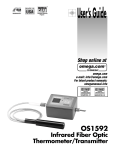
INTRODUCTION HH806U/HH806AU OMEGAnet® On-Line Service omega.com MULTILOGGER THERMOMETER M4502/0707 INSTRUCTION SHEET Shop online at: omega.com e-mail: [email protected] For latest product manuals: omegamanual.info Internet e-mail [email protected] Servicing North America: U.S.A: ISO 9001 Certified Canada: One Omega Drive, Box 4047 Stamford, CT 06907-0047 Tel: (203) 359-1660 FAX: (203) 359-7700 e-mail: [email protected] 976 Bergar Laval (Quebec) H7L 5A1, Canada Tel: (514) 856-6928 FAX: (514) 856-6886 e-mail: [email protected] For immediate technical or application assistance: U.S.A and Canada: Sales Service: 1-800-826-6342/1-800-TC-OMEGA® Customer Service: 1-800-622-2378/1-800-622-BEST® Engineering Service: 1-800-872-9436/1-800-USA-WHEN® TELEX: 996404 EASYLINK: 62968934 CABLE: OMEGA Mexico: En Espanol: (001) 203-359-7803 e-mail: [email protected] FAX: (001) 203-359-7807 [email protected] Servicing Europe: Benelux: Postbus 8034, 1180 LA Amstelveen, The Netherlands Tel: +31 (0)20 3472121 FAX: +31 (0)20 6434643 Toll Free in Benelux: 0800 0993344 e-mail: [email protected] Czech Republic: Frystatska 184, 733 01 Karviná, Czech Republic Tel: +420 (0)59 6311899 FAX: +420 (0)59 6311114 Toll Free: 0800-1-66342 e-mail: [email protected] France: 11, rue Jacques Cartier, 78280 Guyancourt, France Tel: +33 (0)1 61 37 2900 FAX: +33 (0)1 30 57 5427 Toll Free in France: 0800 466 342 e-mail: [email protected] Germany/ Daimlerstrasse 26, D-75392 Deckenpfronn, Germany Austria: Tel: + 49 (0)7056 9398-0 FAX: +49 (0)7056 9398-29 Toll Free in Germany: 0800 639 7678 e-mail: [email protected] United Kingdom: ISO 9002 Certified One Omega Drive, River Bend Technology Centre Northbank, Irlam, Manchester M44 5BD United Kingdom Tel: +44 (0)161 777 6611 FAX: +44 (0)161 777 6622 Toll Free in United Kingdom: 0800-488-488 e-mail: [email protected] It is the policy of OMEGA Engineering, Inc. to comply with all worldwide safety and EMC/EMI regulations that apply. OMEGA is constantly pursuing certification of its products to the European New Approach Directives. OMEGA will add the CE mark to every appropriate device upon certification. The information contained in this document is believed to be correct, but OMEGA accepts no liability for any errors it contains, and reserves the right to alter specifications without notice. WARNING: These products are not designed for use in, and should not be used for, human applications. The instrument is a portable digital thermometer that measures external thermocouples of type K, J, R, S, T, E, N. The thermocouples types comply with the N.I.S.T. – ITS 90 standard reference temperature/voltage tables. The thermometer features a dual thermocouple input, an adjustable T/C offset and an USB interface for uploading data to a PC using optional software and cable. SAFETY INFORMATION WARNING To avoid electrical shock, do not use this instrument when working voltages at the measurement surface over 24V AC or DC. WARNING To avoid damage or burns, do not make temperature measurement in microwave ovens. CAUTION Repeated sharp flexing can break the thermocouple leads. To prolong lead life, avoid sharp bends in the leads, especially near the connector. SPECIFICATIONS ELECTRICAL Temperature Scale: Celsius or Fahrenheit user-selectable Measurement Range: K-TYPE (0.1°) -200°C to 1372°C (-328°F to 2501°F) J-TYPE (0.1°) -210°C to 1200°C (-346°F to 2192°F) T-TYPE (0.1°) -200°C to 400°C (-328°F to 752°F) E-TYPE (0.1°) -210°C to 1000°C (-346°F to 1832°F) R-TYPE (1°) 0°C to 1767°C (32°F to 3212°F) S-TYPE (1°) 0°C to 1767°C ( 32°F to 3212°F) N-TYPE (0.1°) -50°C to 1300°C ( -58°F to 2372°F) *Based on the ITS-90 temperature standard. According to temperature standard ITS-90. Accuracy: K/J/T/E-TYPE ±(0.05% rdg + 0.3°C) on -50°C to 1372°C ±(0.05% rdg + 0.7°C) on -50°C to -210°C ±(0.05% rdg + 0.6°F) on -58°F to 2501°F ±(0.05% rdg + 1.4°F) on -58°F to -346°F N-TYPE ±(0.05% rdg + 0.8°C) on -50°C to 0°C ±(0.05% rdg + 0.4°C) on 0°C to 1300°C ±(0.05% rdg + 1.6°F) on -58°F to 32°F ±(0.05% rdg + 0.8°F) on 32°F to 2372°F R/S-TYPE ±(0.05% rdg + 2°C) on 0°C to 1767°C ±(0.05% rdg + 4°F) on 32°F to 3212°F Temperature Coefficient: 0.1 times the applicable accuracy specification per °C from 0°C to 18°C and 28°C to 50°C (32°F to 64°F and 82°F to122°F). Input Protection: 24V dc or 24V ac rms maximum input voltage on any combination of input pins. Reading Rate: 2.5 time per second. ENVIRONMENTAL Ambient Operating Ranges: 0°C to 50°C (32°F to 122°F) <80% R.H. Storage Temperature: -20°C to 60°C (-4°F to 140°F) <70% R.H. GENERAL Display: There are three display areas on the HH806 series LCD (liquid crystal display). The Main and Second displays are 4 ½ digits with a maximum reading of 19999. These are used for displaying the value of T1 or T2. The Third display is for the date, time, or the differential value of T1 to T2. Overload: “----.-” or “OL” is display. Battery: 1.5V x 4 PCS (SIZE AAA) UM-4 R03. Battery Life: 120 hours typical with carbon zinc battery. Dimensions: 160mm(H) x 83mm(W) x 38mm(D). Weight: Approx. 365g including batteries. Supplied Thermocouple: 1 meter (40”) type K insulated beaded wire thermocouple. Maximum insulation temperature is 482°C (900°F). Thermocouple accuracy is ±1.1°C or 0.4% of reading (whichever is greater) from 0°C to 1250°C. Wire Communication Protocol: 2400 baud rate. (HH806U) 19200 baud rate. (HH806A) External Connections: 1. USB Port 2. DC power JACK(12V) 1 2 OPERATING INSTRUCTIONS 1. OPERATIONAL MODE There are three operation modes-Normal, Shift, and Setup Mode. NORMAL MODE: This is the default mode, the operating functions for the normal mode are printed on the top of each button in white. SHIFT MODE: The operating functions for the shift mode are printed in gray on the buttons. While in the normal mode, press the SHIFT button to switch to shift mode. At the lower-right corner of the display, the word “Shift” is displayed to indicate shift mode. To switch back to normal mode, press the SHIFT button again. SETUP MODE: Press the set[ ] button in normal mode to switch to setup mode, the indicator “SET” is shown on the left side of the display. To switch back to normal mode, press SET[ ] button. 2. NORMAL MODE The following functions can only be used in the normal mode. (1) “ ” Power Button The “ ” button turns the thermometer on or off. When the meter is in MAX/MIN record mode, the power off function is disabled. (2) “[LIMITS]” Button (only Main display) The limits function will alert the user when a measurement exceeds a specified limit. To set the limit values, refer to limits function in the setup mode. Press the [LIMITS] button to activate the limits function; the word “LIMIT” should be displayed on the LCD. When the value of the main display exceeds the Hi limit, the word “Hi” will be displayed and the thermometer will beep in a pulsed tone. If the value of the main display is lower then the Lo limit, the word “Lo” will be displayed and the thermometer will beep in a continuous tone. To exit the limits function, press the [LIMITS] button. (3) “ ” Button The backlight function is represented by this button “ ”. Pressing the button will turn on or off the LCD backlight. The backlight will turn off automatically after. (4) “SAVE/READ” Button The read data function works in conjunction with the save function in the shift mode, it is used for reading saved data. The save function can be activated in shift mode. Press the SAVE/READ button to read saved data; the word “READ” should be displayed on the LCD. To navigate around the save data table, press the overlay “SECOND” button until the “#” sign is displayed on the second display. The location of the read pointer within the saved data table will be displayed. The arrow buttons on the overlay are used for scrolling through the saved data. Press the smaller arrows “ ” or “ ” to step through the data one at a time. Press the larger arrows “ ” or “ ” to step through the data ten at a time. Pressing the overlay “ESC” button deactivates the read data function. (5) “LOG/READ” Button The read log function works in conjunction with the log function. It is used for reading logged data. The log function can be activated in the shift mode. Press the LOG/READ button to activate the log read function; the word “READ” is displayed on the LCD. Press the overlay SECOND button to rotate through following display menus: T1, T2, GRP, and #. T1 and T2: Displays the T1 or T2 saved data. GRP: Displays the current group number. #: Displays the current location of the read pointer within a selected group. The arrow buttons on the overlay are used for scrolling through the data and groups. Press the smaller arrows “ ” or “ ” to step through the logged data or groups one at a time. Press the larger arrows “ ” or “ ” to step through the data or groups ten at a time. To navigate the logged data and groups, press the overlay SECOND button until GRP appears in the second display panel. Then select the group using the arrows. Press the SECOND button again until the “#” sign is displayed. The location of the read pointer in the selected group will be displayed. Use the arrows to scroll through the data. Pressing the overlay “ESC” button deactivates the read data function. (7) HOLD Mode (only Main display) When HOLD mode is selected, the thermometer holds the present readings and stops all further measurements. To activate the data hold mode, press the HOLD button, and “HOLD” is displayed on the LCD. Pressing the HOLD button again cancels the function, and the instrument will automatically resume measurements. (8) MIN/MAX with Time record Mode (only Main display) The MIN/MAX function records the highest and lowest value recorded, and it calculates the average reading, and the differences of MAX to MIN. Press MIN/MAX button to enter the MIN/MAX recording mode. The beeper emits a tone when a new minimum or maximum measurement is recorded. Press the MIN/MAX button again to rotate through the current readings: MAX: The highest measurement recorded. MIN: The lowest measurement recorded. MAX-MIN: The difference of the highest and the lowest measurement. AVG: The average values of the measurements. This mode works in conjunction with the hold function, pressing the HOLD button will stop the recording and measurements (Previously recorded readings are not erased). Press HOLD button again to resume recording and measurements. To prevent accidental loss of MIN, MAX and AVG data, the MIN/MAX function can only be cancelled by pressing and holding down the MIN MAX key for more then 2 seconds. The automatic power-off feature, and the power, °C/°F, REL, SET, Hi/Lo Limits, TYPE, T1/T2 buttons are also disabled. (10) “T1/T2” Button (Main display) The input selection button [T1/T2] selects the input for the main display, T1 thermocouple or T2 thermocouple. Press the T1/T2 button to switch between the two inputs. When meter is turned on, it is set to the display that was last in use. (11) “T1/T2” Button (Second display) The input selection button [T1/T2] selects the input for the second display, T1 thermocouple or T2 thermocouple. Press the T1/T2 button to switch between the two inputs. When meter is turned on, it is set to the display that was last in use. (12) “T1-T2/TIME” Button (Third display) The input selection button [T1-T2] selects the system time and date, or the differential between the two thermocouples (T1-T2) for the third display. Press the T1-T2 button to switch the display options. When meter is turned on, it is set to the display that was last in use. function. (6) “CLR ?” Button The CLR function clears all the saved and logged data in memory. When the CLR button is pressed, indicator “MEM” is displayed and the “CLR” on upper-right of LCD will blink. Pressing the “ENTER” button printed on the overlay in white will clear all saved and logged data. Press “ESC” button to exit this function without clearing data. (7) “REL” Button (Main display) The relative value function can be used for comparing the saved reference value with other measurements. Press the “REL” button to store the current measurement as the reference value, and “REL” should be displayed on the right part of the LCD. The next measurement will display the current value compared to the reference value. Press “REL” button again to clear the reference value and deactivate the relative value measurement function. (8) “APO” Button 3. SHIFT MODE The following functions can only be used in the shift mode. (2) “°C/°F” Button Press the °C/°F button to select the temperature scale, readings can be displayed in Celsius (°C) or Fahrenheit (°F). When the thermometer is turned on, it is set to the temperature scale that was last in use. (4) “SAVE” Button The save function stores the T1, T2 data in a nonvolatile memory. Press the SAVE button to save the current data, the word SAVE is displayed to indicate the data has been saved. The built in memory can store up to 128 data (HH806U)/256 data (HH806AU). The data can be read using the read function in the normal mode. (5) “LOG” Button (HH806U) The data log function continuously records the data according to a specified time interval. The time interval can be set using the interval setup function [INVT] in the set up mode. Press the LOG button to activate the log function; the indicators “LOG” and “MEM” will be displayed on the LCD. There are 16 groups that are used for storing the log data, and each group uses 64 data slots. If the current log session exceeds 64 data, the log function will automatically use the next group to store the following data. A maximum of 1024 data point can be saved in one log session. Press the LOG button again to exit the data log function. “LOG” Button (HH806AU) The data log function continuously records the data according to a specified time interval. The time interval can be set using the interval setup function [INVT] in the set up mode. Press the LOG button to activate the log function; the indicators “LOG” and “MEM” will be displayed on the LCD. There are 16 groups that are used for storing the log data. A maximum of 16,000 data point can be saved in one log session. Pressing the LOG button again to exit the data log Press the APO button to turn the “Auto power off” function on or off. When this function is enabled, the indicator “APO” is shown at the upper left part of the LCD. When APO (Auto power off) is enabled, it will automatically turn the thermometer off no button is pressed for a period longer than the set time interval (the default time for APO is 5 minutes). Press power button to resume operation. (10) “TYPE” Button (Main display) Press this button to change the type of thermocouple in the main display (K/J/T/E/R/S/N). If the inputs of the main and second display are the same, then pressing this button will change the thermocouple type for both displays. (11) “TYPE” Button (Second display) Press this button to change the type of thermocouple in the second display (K/J/T/E/R/S/N). If the inputs of the main and second display are the same, then pressing this button will change the thermocouple type for both displays. 4. SETUP MODE The following functions can only be use in the setup mode. (2) “[LIMITS]” Button (Hi/Lo limit setting) Press the LIMITS button to enter the Hi/Lo limit setup function. The words “LIMIT” and “Hi” will be flash on the LCD along with the previous value for the Hi limit. Enter the new Hi limit value using the number keys printed in white on the overlay. The resolution of Hi/Lo limit setup is 1 count. The “-” button (same button as the ESC) can be used to enter negative values. Press the “ENTER” button to confirm the new limit. You will then be prompted to enter a new Lo limit value. Enter the new value and then press enter to finish setup of limits. (3) “[INVT]” Button (Interval time setting) To setup the time interval for the log function, press the [INVT] button. The indicator “INV” will blink on the top-right of the LCD and the previous interval is displayed. Press the number buttons printed in white on the overlay to change the time interval. Setting is from left to right of the following format (HH:MM:SS). Press the overlay “ENTER” button to confirm. To exit this function, press the ESC button. HH: interval Hour (0~23) MM: interval Minute (0~59) SS: interval Second (0~59) MAX: 23:59:59 MIN: 00:00:01 (8) “APO” Button (Auto power off time setting, min. 1 minute) Use this function to change the time for the auto power off (APO) function. Press the APO button in setup mode, and the indicator “APO” and the current time will flash on the LCD. The default time for APO is 5 minutes. Press the number button printed in white on the overlay to set the APO time. Press the overlay “ENTER” button to confirm. To exit this function without changing the setting, press the ESC button. MAX: 19999 minutes MIN: 0001 minutes (9) “[OFS]” Button (Thermocouple offset adjust) When the main display input is T1 and a thermocouple is connected, the instrument can adjust the offset of the thermocouple. The same can be done for T2 when on the main display. In the setup mode, press this button to enter the thermocouple Offset Setup Function (OFS) and the indicator CAL should be displayed on the top-right of the LCD and the current setting is also shown. Press the number buttons printed in white on the overlay to change the offset of the thermocouple. The resolution of the setup is 0.1°. Press the “-” button to set a negative value. Press the overlay “ENTER” button to confirm. MAX: ±1999.9 °C/°F. (12) “[TIME]” Button (System time setting) To set the system time, press the [TIME] button in the setup mode. The third display should show the current date and time with the year flashing. Enter the new value from left to right in the following format YY:MM:DD and HH:MM:SS. Press the number buttons printed in white on the overlay to set the system date and time. Press the “ENTER” button to confirm. Exit this function by pressing ESC button. OPERATOR MAINTENANCE WARNING To avoid possible electrical shock, disconnect the thermocouple connectors from the thermometer before removing the cover. Battery Replacement 1. Power is supplied by 4pcs 1.5V (AAA SIZE) UM-4 R03. 2. The “ ” appears on the LCD display when replacement is needed. To replace battery remove screw from back of meter and lift off the battery cover. 3. Remove the battery from battery contacts and replace. 4. When not in use for long periods remove battery. 5. Do not store in locations with high temperatures, or high humidity. Cleaning Periodically wipe the case with a damp cloth and detergent, do not use abrasives or solvents. *Software Operation manual is in the Software disk. WARRANTY / DISCLAIMER OMEGA ENGINEERING, INC. warrants this unit to be free of defects in materials and workmanship for a period of 13 months from date of purchase. OMEGA’s WARRANTY adds an additional one (1) month grace period to the normal one (1) year product warranty to cover handling and shipping time. This ensures that OMEGA’s customers receive maximum coverage on each product. If the unit malfunctions, it must be returned to the factory for evaluation. OMEGA’s Customer Service Department will issue an Authorized Return (AR) number immediately upon phone or written request. Upon examination by OMEGA, if the unit is found to be defective, it will be repaired or replaced at no charge. OMEGA’s WARRANTY does not apply to defects resulting from any action of the purchaser, including but not limited to mishandling, improper interfacing, operation outside of design limits, improper repair, or unauthorized modification. This WARRANTY is VOID if the unit shows evidence of having been tampered with or shows evidence of having been damaged as a result of excessive corrosion; or current, heat, moisture or vibration; improper specification; misapplication; misuse or other operating conditions outside of OMEGA’s control. Components which wear is not warranted, include but are not limited to contact points, fuses, and triacs. OMEGA is pleased to offer suggestions on the use of its various products. However, OMEGA neither assumes responsibility for any omissions or errors nor assumes liability for any damages that result from the use of its products in accordance with information provided by OMEGA, either verbal or written. OMEGA warrants only that the parts manufactured by it will be as specified and free of defects. OMEGA MAKES NO OTHER WARRANTIES OR REPRESENTATIONS OF ANY KIND WHATSOEVER, EXPRESS OR IMPLIED, EXCEPT THAT OF TITLE, AND ALL IMPLIED WARRANTIES INCLUDING ANY WARRANTY OF MERCHANTABILITY AND FITNESS FOR A PARTICULAR PURPOSE ARE HEREBY DISCLAIMED. LIMITATION OF LIABILITY: The remedies of purchaser set forth herein are exclusive, and the total liability of OMEGA with respect to this order, whether based on contract, warranty, negligence, indemnification, strict liability or otherwise, shall not exceed the purchase price of the component upon which liability is based. In no event shall OMEGA be liable for consequential, incidental or special damages. CONDITIONS: Equipment sold by OMEGA is not intended to be used, nor shall it be used: (1) as a “Basic Component” under 10 CFR 21 (NRC), used in or with any nuclear installation or activity; or (2) in medical applications or used on humans. Should any Product(s) be used in or with any nuclear installation or activity, medical application, used on humans, or misused in any way, OMEGA assumes no responsibility as set forth in our basic WARRANTY / DISCLAIMER language, and, additionally, purchaser will indemnify OMEGA and hold OMEGA harmless from any liability or damage whatsoever arising out of the use of the Product(s) in such a manner. RETURN REQUESTS / INQUIRIES Direct all warranty and repair requests / inquiries to the OMEGA Customer Service Department. BEFORE RETURNING ANY PRODUCT(S) TO OMEGA, PURCHASER MUST OBTAIN AN AUTHORIZED RETURN (AR) NUMBER FROM OMEGA’S CUSTOMER SERVICE DEPARTMENT (IN ORDER TO AVOID PROCESSING DELAYS). The assigned AR number should then be marked on the outside of the return package and on any correspondence. The purchaser is responsible for shipping charges, freight, insurance and proper packaging to prevent breakage in transit. FOR WARRANTY RETURNS, please have the following information available BEFORE contacting OMEGA: 1. Purchase Order number under which the product was PURCHASED, 2. Model and serial number of the product under warranty, and 3. Repair instructions and/or specific problems relative to the product. FOR NON-WARRANTY REPAIRS, consult OMEGA for current repair charges. Have the following information available BEFORE contacting OMEGA: 1. Purchase Order number to cover the COST of the repair, 2. Model and serial number of the product, and 3. Repair instructions and/or specific problems relative to the product. OMEGA’s policy is to make running changes, not model changes, whenever an improvement is possible. This affords our customers the latest in technology and engineering. OMEGA is a registered trademark of OMEGA ENGINEERING, INC. © Copyright 2007 OMEGA ENGINEERING, INC. All rights reserved. This document may not be copied, photocopied, reproduced, translated, or reduced to any electronic medium or machine-readable form, in whole or in part, without the prior written consent of OMEGA ENGINEERING, INC. Where Do I Find Everything I Need for Process Measurement and Control? OMEGA…Of Course! Shop online at omega.com TEMPERATURE Thermocouple, RTD & Thermistor Probes, Connectors, Panels & Assemblies Wire: Thermocouple, RTD & Thermistor Calibrators & Ice Point References Recorders, Controllers & Process Monitors Infrared Pyrometers PRESSURE, STRAIN AND FORCE Transducers & Strain Gages Load Cells & Pressure Gages Displacement Transducers Instrumentation & Accessories FLOW/LEVEL Rotameters, Gas Mass Flowmeters & Flow Computers Air Velocity Indicators Turbine/Paddlewheel Systems Totalizers & Batch Controllers pH/CONDUCTIVITY pH Electrodes, Testers & Accessories Benchtop/Laboratory Meters Controllers, Calibrators, Simulators & Pumps Industrial pH & Conductivity Equipment DATA ACQUISITION Data Acquisition & Engineering Software Communications‐Based Acquisition Systems Plug‐in Cards for Apple, IBM & Compatibles Datalogging Systems Recorders, Printers & Plotters HEATERS Heating Cable Cartridge & Strip Heaters Immersion & Band Heaters Flexible Heaters Laboratory Heaters ENVIRONMENTAL MONITORING AND CONTROL Metering & Control Instrumentation Refractometers Pumps & Tubing Air, Soil & Water Monitors Industrial Water & Wastewater Treatment pH, Conductivity & Dissolved Oxygen Instruments Made in Taiwan