1
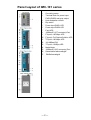
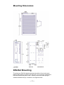
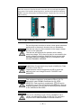
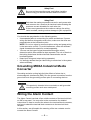
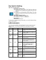
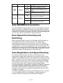
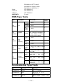
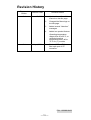
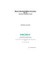
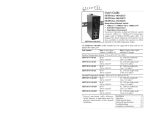
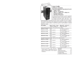
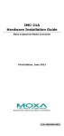
Installation Instructions IMC-101 1TX to 1MMFX Ethernet Converter Trend supply the following Ethernet media converter: IMC-101-M-SC :Industrial10/100BaseT(X) to 100 BaseFX Converter, multi mode, SC connector, 0 to 60 °C Other options referred to in the installation instructions, and other accessories are not supplied. The attached installation instructions are supplied by Moxa Networking Company Ltd: P/No: 18020010102 edition 3, 01/07/04 For additional information see IMC-101 data sheet TA200837 IMC-101 Installation Instructions TG200840 Issue 1/A 10/12/04 1 IMC-101 Installation Instructions This page is left intentionally blank Trend Control Systems Ltd reserves the right to revise this publication from time to time and make changes to the content hereof without obligation to notify any person of such revisions or changes. P.O. Box 34, Horsham, West Sussex, RH12 2YF United Kingdom Telephone +44 (0)1403 211888 E-mail [email protected] 2 Fax (International) +44 (0)1403 210982 Website www.trend-controls.com Fax (UK) +44 (0)1403 241608 Registered office. Novar House 24 Queens Road Weybridge Surrey KT13 9UX Registered in England No 1664519 IMC-101 Installation Instructions TG200840 Issue 1/A 10/12/04 MOXA Industrial Media Converter IMC-101 Hardware Installation Guide Third Edition, July 2004 Overview MOXA Industrial Media Converter, which is specially designed for a reliable and stable operation in harsh industrial environments, provides industrial grade media conversion between 10/100BaseT(X) and 100BaseFX. Its reliable industrial design is excellent for keeping your industrial automation applications running continually, and comes with a relay output warning alarm to help prevent damages and losses. This product has a wide operating temperature range, from -40 to 75°C, and are designed to withstand a high degree of vibration and shock. The rugged hardware design makes IMC-101 perfect for ensuring that your Ethernet equipment can withstand critical industrial applications, such as in hazardous locations (Class 1 Division 2/Zone 2), and complies with FCC, TÜV, UL, and CE Standards NOTE Throughout this Hardware Installation Guide, we often use IMC as an abbreviation for MOXA Industrial Media Converter : IMC = MOXA Industrial Media Converter Package Checklist MOXA Industrial Media Converter is shipped with the following items. If any of these items is missing or damaged, please contact your customer service representative for assistance. MOXA Industrial Media Converter Hardware Installation Guide MOXA Product Warranty booklet Features Supports 10/100Base-TX auto-negotiation and auto-MDI/MDI-X Multi mode, single mode with SC or ST fiber connector available Supports Link Fault Pass-Through Relay Output alarm when a port breaks or the power fails Redundant 12 to 48 VDC power inputs, DIN-Rail or panel mountable Operating temperature ranges from 0 to 60°C, or extended operting temperature from –40 to 75°C for (-T) models —1— Panel Layout of IMC-101 series 1. Grounding screw 2. Terminal block for power input PWR1/PWR2 and relay output 3. Heat dissipation orifices 4. Dip switch 5. Power input PWR1 LED 6. Power input PWR2 LED 7. Fault LED 8. 100BaseFX (ST connector) Port 9. FX port’s 100 Mbps LED 10. FX port’s Full Duplex/Collision LED 11. TP port’s 100 Mbps LED 12. 10/100BaseT(X) 13. TP port’s 10 Mbps LED 14. Model Name 15. 100BaseFX (SC connector) Port 16. Screw hole for wall mounting kit 17. DIN-Rail mounting kit —2— Mounting Dimensions (Unit = mm) DIN-Rail Mounting The aluminum DIN-Rail attachment plate should be fixed to the back panel of IMC when you take it out of the box. If you need to reattach the DIN-Rail attachment plate to IMC, make sure the stiff metal spring is situated towards the top, as shown in the figures below. —3— STEP 1: Insert the top of the DIN-Rail into the slot just below the stiff metal spring. STEP 2: The DIN-Rail attachment unit will snap into place as shown below. To remove MOXA Industrial Media Converter from the DIN-Rail, simply reverse Steps 1 and 2 above. Wall Mounting (OPTIONAL) For some applications, you will find it convenient to mount MOXA Industrial Media Converter on the wall, as illustrated below. STEP 1: Remove the aluminum DIN-Rail attachment plate from MOXA Industrial Media Converter, and then attach the wall mount plates, as shown in the diagrams below. STEP 2: Mounting MOXA Industrial Media Converter on the wall requires 4 screws. Use the IMC, with wall mount plates attached, as a guide to mark the correct locations of the 4 screws. The heads of the screws should be less than 6.0 mm in diameter, and the shafts should be less than 3.5 mm in diameter, as shown in the figure at the right. NOTE Test the screw head and shank size by inserting the screw into one of the keyhole shaped apertures of the Wall Mounting Plates, before it is screwed into the wall. Do not screw the screws in all the way—leave a space of about 2 mm to allow room for sliding the wall mount panel between the wall and the screws. -- 4 -- STEP 3: Once the screws are fixed in the wall, insert the four screw heads through the large parts of the keyhole-shaped apertures, and then slide MOXA Industrial Media Converter downwards, as indicated below. Tighten the four screws for added stability. Wiring Requirements Warning Warning Warning Do not disconnect modules or wires unless power has been switched off or the area is known to be non hazardous. The devices may only be connected to the supply voltage shown on the type plate. The devices are designed for operation with a safety extra-low voltage. Thus, they may only be connected to the supply voltage connections and to the signal contact with the safety extra-low voltages (SELV) in compliance with IEC950/ EN60950/ VDE0805. Substitution of components may impair suitability for Class I, Division 2 and Zone 2. These devices must be supplied by a SELV source as defined in the Low Voltage Directive 73/23/EEC and 93/68/EEC. This equipment has been evaluated as EEx nC IIC T4 equipment under DEMKO Certificate No. 03 ATEX II 3G and is 0324537U. Each module is marked with suitable for use in Zone 2 Explosive Atmospheres. Devices must be installed in a minimum IP 54 enclosure as defined in IEC 60529 and EN 60529. This unit is a building-in type. During installation into a certain end equipment it shall comply with fire enclosure request of IEC 60950/EN60950 or similar sentence. —5— Safety First! Be sure to disconnect the power cord before installing and/or wiring your MOXA Industrial Media Converter. Safety First! Calculate the maximum possible current in each power wire and common wire. Observe all electrical codes dictating the maximum current allowable for each wire size. If the current goes above the maximum ratings, the wiring could overheat, causing serious damage to your equipment. You should also pay attention to the following points: Use separate paths to route wiring for power and devices. If power wiring and device wiring paths must cross, make sure the wires are perpendicular at the intersection point. NOTE: Do not run signal or communications wiring and power wiring in the same wire conduit. To avoid interference, wires with different signal characteristics should be routed separately. You can use the type of signal transmitted through a wire to determine which wires should be kept separate. The rule of thumb is that wiring that shares similar electrical characteristics can be bundled together. Keep input wiring and output wiring separated. It is strongly advised that you label wiring to all devices in the system when necessary. Grounding MOXA Industrial Media Converter Grounding and wire routing help limit the effects of noise due to electromagnetic interference (EMI). Run the ground connection from the ground screw to the grounding surface prior to connecting devices. This product is intended to be mounted to a well-grounded mounting surface such as a metal panel. Wiring the Alarm Contact The Alarm Contact consists of two middle contacts of the terminal block on IMC’s top panel. You may refer to the next section for detailed instructions on how to connect the wires to the terminal block connector, and how to attach the terminal block connector to the terminal block receptor. In this section, we will explain the meaning of the two contacts used to connect the Alarm Contact. —6— FAULT: The two middle contacts of the 6-contact terminal block connector are used to detect both power faults and port faults. The two wires attached to the Fault contacts form an open circuit when: 1. IMC has lost power from one of the DC power inputs. OR 2. One of the ports for which the corresponding PORT ALARM Dip Switch is set to ON is not properly connected. If neither of these two conditions occurs, the Fault circuit will be closed. Wiring the Redundant Power Inputs The top two contacts and the bottom two contacts of the 6-contact terminal block connector on IMC’s top panel are used for IMC’s two DC inputs. Top and front views of one of the terminal block connectors are shown here. STEP 1: Insert the negative/positive DC wires into the V-/V+ terminals. STEP 2: To keep the DC wires from pulling loose, use a small flat-blade screwdriver to tighten the wire-clamp screws on the front of the terminal block connector. STEP 3: Insert the plastic terminal block connector prongs into the terminal block receptor, which is located on IMC’s top panel. Before connecting IMC to the DC power inputs, make sure the DC power source voltage is stable. —7— Communication Connections IMC-101 models have one 10/100BaseT(X) Ethernet port, and one 100BaseFX (SC or ST type connector) fiber port. 10/100BaseT(X) Ethernet Port Connection The 10/100BaseT(X) ports located on IMC’s front panel are used to connect to Ethernet-enabled devices. Below we show pinouts for both MDI (NIC-type) ports and MDI-X (HUB/Switch-type) ports, and also show cable wiring diagrams for straight-through and cross-over Ethernet cables. RJ45 (8-pin, MDI) Port Pinouts RJ45 (8-pin, MDI-X) Port Pinouts RJ45 (8-pin) to RJ45 (8-pin) Straight-Through Cable Wiring RJ45 (8-pin) to RJ45 (8-pin) Cross-Over Cable Wiring 100BaseFX Ethernet Port Connection The concept behind the SC port and cable is quite straightforward. Suppose you are connecting devices I and II. Contrary to electrical signals, optical signals do not require a circuit in order to transmit data. Consequently, one of the optical lines is used to transmit data from device I to device II, and the other optical line is used transmit data from device II to device I, for full-duplex transmission. All you need to remember is to connect the Tx (transmit) port of device I to the Rx (receive) port of device II, and the Rx (receive) port of device I to the Tx (transmit) port of device II. If you are making your own cable, we suggest labeling the two sides of the same line with the same letter (A-to-A and B-to-B, as shown below, or A1-to-A2 and B1-to-B2). —8— SC-Port Pinouts SC-Port to SC-Port Cable Wiring ST-Port Pinouts ST-Port to ST-Port Cable Wiring This is Class 1 Laser/LED product. Do not stare into the Laser Beam. Redundant Power Inputs Both power inputs can be connected simultaneously to live DC power sources. If one power source fails, the other live source acts as a backup, and automatically supplies all of MOXA Industrial Media Converter’s power needs. Alarm Contact MOXA Industrial Media Converter has one Alarm Contact located on the top panel. For detailed instructions on how to connect the Alarm Contact power wires to the two middle contacts of the 6-contact terminal block connector, see the Wiring the Alarm Contact section above. A typical scenario would be to connect the Fault circuit to a warning light located in the control room. The light can be set up to switch on when a fault is detected. The Alarm Contact has two terminals that form a Fault circuit for connecting to an alarm system. The two wires attached to the Fault contacts form an open circuit when (1) IMC has lost power from one of the DC power inputs, or (2) one of the ports for which the corresponding PORT ALARM Dip Switch is set to ON is not properly connected. If neither of these two conditions occurs, the Fault circuit will be closed. —9— Dip Switch Setting IMC-101 series DIP switch Dip Switch 1 (Default: Off ) ON: Enables the PORT Alarm. If the port’s link fails, the relay will form an open circuit and the fault LED will light up. Off: Disables the corresponding PORT Alarm. The relay will form a closed circuit and the Fault LED will never light up. Dip Switch 2 (Default: ON ) ON: Enable full duplex for 100BaseFX Off: Disables full duplex for 100BaseFX Dip Switch 3 Reserved for future use To activate the updated setting of dip switch, you need to power off then power on the switch. LED Indicators The front panel of MOXA Industrial Media Converter contains several LED indicators. The function of each LED is described in the table below. LED PWR1 PWR2 Fault 10M 100M (TP) Color State Description On Power is being supplied to power input P1 Off Power is not being supplied to power input P1 On Power is being supplied to power input P2 Off Power is not being supplied to power input P2 On When the corresponding PORT alarm is enabled, and the port’s link is inactive. Off When the corresponding PORT alarm is enabled and the port’s link is active, or when the corresponding PORT alarm is disabled. On TP port’s 10 Mbps link is active Blinking Data is being transmitted at 10 Mbps AMBER AMBER RED GREEN GREEN Off TP Port’s 10 Mbps link is inactive On TP port’s 100 Mbps link is active Blinking Data is being transmitted at 100 Mbps — 10 — 100M (FX) FDX/COL GREEN GREEN Off 100BaseTX Port’s link is inactive On FX port’s 100 Mbps is active Blinking Data is being transmitted at 100 Mbps Off 100BaseFX port is inactive On 100BaseFX port is being transmitted at full duplex Blinking Off Collision occurs 100BaseFX port is being transmitted at half duplex Auto MDI/MDI-X Connection The Auto MDI/MDI-X function allows users to connect MOXA Industrial Media Converter’s 10/100BaseTX ports to any kind of Ethernet device, without paying attention to the type of Ethernet cable being used for the connection. This means that you can use either a straight-through cable or cross-over cable to connect IMC to Ethernet devices. Dual Speed Functionality and Switching MOXA Industrial Media Converter’s 10/100 Mbps RJ45 switched port auto negotiates with the connected device for the fastest data transmission rate supported by both devices. All models of MOXA Industrial Media Converter are plug-and-play devices, so that software configuration is not required at installation, or during maintenance. The half/full duplex mode for the RJ45 switched ports is user dependent and changes (by auto-negotiation) to full or half duplex, depending on which transmission speed is supported by the attached device. Auto-Negotiation and Speed Sensing All of MOXA Industrial Media Converter’s RJ45 Ethernet ports independently support auto-negotiation for transmission speed in the 10BaseT and 100BaseTX modes, with operation according to the IEEE 802.3u standard. This means that some nodes could be operating at 10 Mbps, while at the same time, other nodes are operating at 100 Mbps. Auto-negotiation takes place when an RJ45 cable connection is made, and then each time a LINK is enabled. MOXA Industrial Media Converter advertises its capability for using either 10 Mbps or 100 Mbps transmission speeds, with the device at the other end of the cable expected to similarly advertise. Depending on what type of device is connected, this will result in agreement to operate at a speed of either 10 Mbps or 100 Mbps. If a MOXA Industrial Media Converter RJ45 Ethernet port is connected to a non-negotiating device, it will default to 10 Mbps speed and half-duplex mode, as required by the IEEE 802.3u standard. — 11 — Specifications Technology Standards Interface RJ45 ports Fiber ports LED Indicators Dip Switch Alarm Contact Optical Fiber Distance Wavelength Min. TX Output Max. TX Output Sensitivity Power Input Voltage Input Current (@24V) Connection Overload Current Protection Reverse Polarity Protection Mechanical Casing Dimensions (W x H x D) Weight Installation Environment Operating Temperature Storage Temperature Ambient Relative Humidity Regulatory Approvals Safety Hazardous Location EMI EMS IEEE802.3, 802.3u, Link Fault Pass-Through 10/100BaseT(X) 100BaseFX (SC, ST connectors available) Power, Fault, 10/100M, Full Duplex/Collision, Port break alarm mask, 100BaseFx Full/Half duplex selection One relay output with current carrying capacity of 1A @ 24 VDC Single mode fiber for 15 km, Multi mode fiber for 2 km 1310 nm -20 dBm (IMC101-M), -15 dBm (IMC101-S) -14 dBm (IMC-101-M), -6 dBm (IMC-101-S) -36 to -32 dBm (IMC101-M), -34 to -32 dBm (IMC101-S) 12 to 48 VDC; Redundant inputs 0.2 A Removable Terminal Block 1.1 A Present IP30 protection, aluminum case 53.6 x 135 x 105 mm 0.63 kg DIN-Rail, Wall Mounting 0 to 60Ƭ (32 to 140 oF),-40 to 75oC (-40 to 167oF) -40 to 85Ƭ (-40 to 185 oF) 5 to 90% (non-condensing) UL60950, UL 508, CSA C22.2 No. 60950, EN60950 UL/cUL Class I, Division 2, Groups A, B, C and D ATEX Class I, Zone 2, EEx nC IIC FCC Part 15, CISPR (EN55022) class A EN61000-4-2 (ESD), level 3 EN61000-4-3 (RS), level 3 — 12 — EN61000-4-4 (EFT), level 3 EN61000-4-5 (Surge), level 3 EN61000-4-2 (CS), level 3 IEC 60068-2-27 IEC 60068-2-32 IEC 60068-2-6 5 years Shock Free Fall Vibration WARRANTY EMS Type Tests Test Description IEC ESD 61000-4-2 IEC Radiated 61000-4-3 RFI Burst IEC 61000-4-4 (Fast Transient) IEC Surge 61000-4-5 Test Levels Air +/- 8 KV discharge Contact +/- 6 KV discharge ESD contact +/- 6 KV indirect 10 V/m, 80 MHz – 1 GHz, AM 1 KHz 80% modulation Housing 10 V/m, .9 GHz – 1.8 GHz, FM 200 Hz 50% square Power supply +/- 2 KV lines Comm. +/- 1 KV lines Severity Levels 3 3 3 3 3 3 3 Relay +/- 1 KV Power supply lines +/- 2 KV, 12Ө, CM; +/- 1KV, 3 2Ө, DM Relay Power supply lines Induced IEC Comm. (Conducted) 61000-4-6 lines RFI Relay +/- 1 KV, 42Ө, CM; +/- 1KV, 42Ө, DM 10 Vrms, 150 KHz – 80 MHz, AM 1 KHz 80% modulation 10 Vrms, 150 KHz – 80 MHz, AM 1 KHz 80% modulation 10 Vrms, 150 KHz – 80 MHz, AM 1 KHz 80% modulation 3 3 3 3 Environmental Type Tests Test Description Test Levels IEC 60068-2-6 Vibration 10 – 500 – 10Hz, 0.5 oct./min., 4g, X, Y, Z (3 axes) IEC 60068-2-27 Shock IEC 60068-2-32 Free Fall 50 g, 11 ms, ̈́X, ̈́Y, ̈́Z (6 directions) 75 cm, 1 corner, 3 edges, 6 faces (total 10 drops) — 13 — MOXA Internet Services Customer satisfaction is our number one concern, and to ensure that customers receive the full benefit of our products, Moxa Internet Services has been set up to provide technical support, driver updates, product information, and user’s manual updates. The following services are provided E-mail for technical support [email protected] World Wide Web (WWW) Site for product information: http://www.moxa.com or http://www.moxa.com.tw — 14 — Revision History Document Edition Revision Date 2nd June 15, 2004 Revision Details 1. Updated the edition of this manual on the title page. 2. Changed the Moxa logo on the title page. 3. Added several “Attention” messages 4. Added one product feature: Operating temperature ranges from 0 to 60°C, or extended operting temperature from –40 to 75°C for (-T) models. 3rd July 1, 2004 1. Revise 100BaseFX for fiber optic port of ST connector. P/NΚ18020010102 — 15 —