1
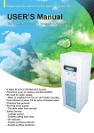
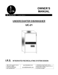
M157304E
157303 & 157304 Manual
ITEM NUMBER:
SERIAL NUMBER:
HP:______ Volts:______ Amp:______ Ph:_____
RPM:____ PSI:____ GPM:____ Nozzle Size:_____
Pump:___________ Hose:______ Lance:_______
Max. Discharge Temperature:_____________
Installation, Operation, and Maintenance Manual
PRESSURE WASHER: Cleans dirty surfaces with high pressure water.
To the Owner:
Thank you for purchasing a Northstar pressure washer. Your machine is designed for long life, dependability,
and the top performance you demand! Take time now to read through this manual so you better understand the
machine’s operation, maintenance and safety precautions. Everyone who operates this machine must read and
understand this manual. The time you take now will prolong your machine’s life and prepare you for its safe
operation. Enjoy the exceptional performance of your Northstar pressure washer, the industry leader! The
manufacturer reserves the right to make improvements in design and/or changes in specifications at any time
without incurring any obligation to install them on units previously sold.
Quick Facts
Pump Oil
Water
Storage
Spraying
Chemicals
Maintenance
Schedule
Pump is shipped with oil. Change oil plug and check pump oil level before starting.
Use SAE 30 Non-detergent pump oil (item# 4043) or Cat Pump oil (item# 22158) for oil
changes.
Make sure your water flow is 20% higher than the pressure washer’s flow rate.
Make sure your water is clean and particle free.
Do not allow water to freeze in the pump, hose, or spray gun.
Use any North Star brand or equivalent pressure washer chemicals.
Adjust soap adjustment knob to regulate cleaning power.
Pump:
Oil: change after first 50 hours, then every 3 months or 500 hours.
Read and understand all manuals before operating.
Any Questions, Comments, Problems or Parts Orders
In the United States
Northstar Customer Service
Call 1-800-270-0810
Hours: Monday - Friday 7:00 AM to 5:30 PM
Saturday 7:30 AM-11:30 AM Central Time
In the United Kingdom
Call 02392639752
Northern Tool and Equipment Co. (UK) Ltd.
Unit 2, Keel Close,
Portsmouth, Hants PO3 5QD, England
1
Table of Contents
Important Safety Instructions
Grounding Instructions
Machine Component Identification
Installation Instructions
Operating Instructions
2
2
3
4-7
8-10
Maintenance Instructions
Long Term Storage
Troubleshooting
Parts Breakdowns
Wiring Diagram
10-11
11
12
12-17
18
Important Safety Instructions
WARNING
-Risk of Injection or Injury to Persons - Do Not Direct Discharge Stream at Persons. - Do not use a hose if
exterior damage is evident.
-Risk of explosion. - Do not spray flammable liquids. - Do not operate in a flammable environment.
CAUTION
-Gun kicks back. Hold with both hands.
-To reduce the risk of injury, read operating instructions carefully before use.
WARNING - When using this product basic precautions should always be followed, including the following:
1.) Read all the instructions before using the product.
2.) To reduce the risk of injury, close supervision is necessary when the product is used near children. Do not allow
irresponsible use by children. Always stop the product and bleed pressures before leaving unattended,
disconnecting hoses, or servicing the pump.
3.) Know how to stop the product and bleed pressures quickly. Be thoroughly familiar with the controls.
4.) Stay alert - watch what you are doing.
5.) Do not operate the product when fatigued or under the influence of alcohol or drugs. Never smoke while operating
this machine.
6.) Keep operating area clear of all persons.
7.) Do not overreach or stand on unstable support. Keep good footing and balance at all times. Wear footwear capable
of maintaining a good grip on wet surfaces - Do not place the machine on soft or unstable ground.
8.) Follow the maintenance instructions specified in all manuals. Do not run machine without sufficient lubrication or
sufficient water to cool the pump.
9.) Wear safety glasses, gloves, face protection and appropriate clothing when operating the machine.
10.) Do not operate this machine with broken or missing parts. - Never alter the manufacturer’s original design or
deactivate any safety device on the machine.
11.) Risk of exposure to dangerous chemicals. Wear protective gloves when handling and cleaning with chemicals.
Follow the chemical manufacturer’s directions. Understand all safety hazards and first aid for all chemicals being
used. Check whether dangerous chemicals have been used and take any precautions that may have been
recommended by the supplier of these chemicals when cleaning filters. Do not pump highly abrasive fluids or use
with incompatible chemicals or solvents.
12.) Know the pressure and temperature limits of your machine. Be sure all high pressure accessories meet or exceed
your machine’s limits. Do not set the pressure relief valve above the machine’s limit.
13.) Do not move this machine by pulling on the hose. Do not use the pump to support other items of equipment that
impose unacceptable loads on the pump. Do not attempt to use this machine as a prop.
14.) To reduce risk of injury, do not secure the spray gun open. Your spray gun is equipped with a built-in trigger safety
latch to guard against accidental trigger release and potentially dangerous high pressure spray. Rotate the safety
latch to the locked position when not spraying.
15.) Do not clean this machine with its own spray. Cleaning should be done with a damp sponge with the electrical
power turned OFF.
Grounding Instructions
This product must be connected to a grounded, metal, permanent wiring system; or an equipment-grounding conductor must be run
with the circuit conductors and connected to the equipment-grounding terminal or lead on the product.
SAVE THESE INSTRUCTIONS
2
Machine Component Identification
157303/157304
Ref #
1
2
3
Description
Inlet/Filter
On/Off Switch
High Pressure Outlet
Ref #
4
5
6
Description
Pump
Unloader
Motor
fig 0 2 2 8 8
3
Installation Instructions
I.) Unpack
Separate and identify all components. Use the assembly instructions in this manual for assembly.
4
HARDWARE BAG: Separate and identify all components. Use the assembly instructions in this manual for assembly.
5
II.) Assembly Instructions
A. 1. To spray chemical, insert the chemical injector into the
quick connect oulet of the pressure washer as shown.
2. Connect the clear hose to the chemical strainer and to
the inlet of the chemical injector. This is inside the base
unit on the 157303, chemical injector can remained
installed at all times. Have hose exit base as shown
below.
3. Install the pressure hose onto the chemical injector as
shown, for 157304. Install on quick connect outlet on
157303.
4. Connect the other end of the pressure hose to the spray
gun as shown.
5. Connect the lance extension to the spray gun and insert
the proper nozzle into the lance end.
6. Make sure all plumbing connections are tight.
7. Install four rubber feet onto base with four 1/4” x 3/4”
flange bolts and four flange nuts. Use the same bolts to install
cross members when installing the rubber feet.
Nozzle
Lance
Extension
Spray
Gun
Quick Connect
Outlet
BRACE
RUBBER FEET
F IG 0 2 3 5
1
Clear
Hose
Chemical
Injector
Chemical
Strainer
High Pressure
Hose
157304 only
Chemical Hose
Exit for 157303
6
III.) Wiring Instructions
This pressure washer is shipped without a power cord and is
intended to be hard wired into your electrical system. The
following instructions will help you to hard wire this unit.
Electrical Requirements:
Item Number
157303
157304
Step 3: Locate terminal block inside the electrical housing and
attach wires (like colors should be across from each other).
Circuit Rating
115V/20A
230V/30A
WARNING: Make sure to use a dedicated circuit that
includes a GFCI. Consult local electrical code for
connection requirements.
A 157304 is shown in the following steps, the 157303 gets
wired the exact same way.
Step 1: Using a 3/8” wrench, remove the roof and the top of
the electrical housing. (Front panel not shown for clairity.)
Step 4: Clamp cord in strain relief nut (thru the bottom of the
panel) by turning nut clockwise.
Step 5: Re-attach the top of the electrical housing and the
roof.
Step 2: Feed power cord through the strain relief nut on the
bottom of the unit into the electrical housing.
POWER SUPPLY CORD
OR CONDUIT
7
Operating Instructions
Read and understand the entire manual before operating the pressure washer.
Follow these instructions every time you use the pressure washer.
I.) Pre-Operation
III.) Before Starting
; A.) Position the machine for easy access to all controls.
; B.) Position the machine on a solid surface, with less
than a three degree slope, and so it is protected from
external damage.
; C.) Make sure ambient lighting is sufficient for the
surface you are cleaning to be seen with ease. Use
artificial light if needed.
; D.) Check hoses, fittings, wand, trigger gun and electrical
cords for signs of wear, cracks and looseness, and
replace as required.
; E.) Check and clean the nozzle orifice.
; F.) Check and clean the water inlet screen and filter.
; G.) Read entire manual, especially the important safety
instructions listed on page 2.
; H.) Check and maintain proper oil levels in the pump.
WARNING: Check hoses, fittings, wand, gun and cords
daily for signs of wear, cracks and looseness, and replace as
required.
1. Connect water supply hose to the garden hose
connector located on the side of the unit.
2. Connect high pressure hose to quick connect outlet
on front of the machine.
3. Connect spray gun to high pressure hose.
4. If detergents will be used, only use detergents
intended for pressure washers. Follow instructions
on the detergent container.
II.) Check Your Water Supply
; A.) Make sure the water supply is clean. Debris can
cause excess pump wear and reduce performance.
; B.) An insufficient water supply will damage your pump.
Make sure the water supply is steady and is 20% over
the rated flow of your pump. Use a stopwatch to
time how long it takes to fill a 5 gallon bucket with
your garden hose.
Example:
If the rated flow is = 3gpm
Then required flow = 3 x 1.20 = 3.6gpm
5gallons / 3.6gpm = 1.39 minutes
1.39min x 60sec/min = 83 seconds
Therefore, you must be able to fill a
5 gallon bucket in 83 seconds or faster.
; C.) The water supply garden hose must have an inside
diameter of at least 5/8”. If the hose is more than 100
ft. long, the diameter must be at least 3/4”.
; D.) Never use a reservoir tank as a water source. This
pressure washer is designed for a pressurized water
source such as a city water faucet. Sucking water out
of a tank may cause pump cavitation and damage to
your pump. However, the inlet pressure of the pump
must not exceed 115 psi (8 bar).
; E.) Always use a flexible rubber hose for your water
supply. Do not use rigid piping.
; F.) Do not pump flammable liquids or liquids containing
incompatible chemicals or solvents.
IV.) To Start
DANGER: Do not point the spray wand at yourself or at any
person. Bodily injury may result from water under high
pressure.
WARNING: Wear eye, ear, hand, foot and skin protection at
all times while operating this pressure washer.
IMPORTANT: The water must be turned on before starting.
Running the pump dry will cause damage and void warranty.
1. Turn water supply ON.
2. Squeeze the trigger to allow air to purge from the system.
(this step goes faster with the pressure nozzle removed)
8
V.) Attach Nozzle
Nozzle
00663
Color of Nozzle:
Red
Yellow
Spray Angle
0
15
Green
White
Black
25
40
Used For:
Highest Impact
Tough Stains/
Stripping
General
Light Cleaning
Low pressure/
Chemical
Application
Your pressure washer is equipped with five nozzles. To install
a nozzle simply pull back the collar and push the nozzle into
the coupler. Once the connection is made, pull on the nozzle to
assure a tight connection.
Nozzle
Lance
Collar Coupler
CORRECT
INCORRECT
WARNING: Make sure the nozzle is correctly
inserted. The nozzle may become a projectile if not
inserted correctly. Do not attempt to use different
types of nozzles that may not fit the coupler.
VI.) Turn the pump switch ON.
1. Make sure the hose is not kinked. A kinked hose
will provide insufficient water supply to the pump and
will reduce its life.
To Clean
WARNING: Wear eye, ear, hand, foot and skin protection at
all times while operating this pressure washer.
DANGER: Do not point the spray wand at yourself or
at any person. Bodily injury may result from water
under high pressure.
IMPORTANT: Your spray gun is equipped with a built-in
trigger safety latch to guard against accidental trigger
actuation and potentially dangerous high pressure spray.
Rotate the safety latch to the locked position when not
spraying.
NOTE: Your pressure washer is equipped with a low
pressure chemical injector. You do not need to use
chemicals for every job, however, the proper chemical used
for the proper application can speed up cleaning jobs
tremendously.
WARNING: Only use North Star pressure washer chemicals
or chemicals specifically formulated for pressure washers.
Follow the chemical manufacturer’s recommendations.
Understand all safety precautions and first aid for all
chemicals.
1. Insert chemical suction line and strainer into a
container of detergent.
2. Completely open the chemical control knob located
on the chemical injector.
3. Insert the chemical application nozzle (Black).
4. Turn the chemical control knob to adjust the
chemical concentration. Spray detergent onto the
surface and allow it to soak. Chemicals need time
(dwell time) to work properly. Follow the chemical
manufacturer’s recommendations for dwell time.
5. Change back to high pressure by inserting the
nozzle with the desired spray angle.
6. Hold the lance with two hands, have a sturdy stance.
7. Point lance at dirty surface and squeeze trigger.
8. Wash from the bottom to the top, using side to side
motions. This washes away heavy dirt and allows
the detergent to soak as you work toward the top.
9. Use the width of the spray pattern to wash in a wide
path. Overlap spray paths for complete coverage.
10. The nozzle should be 12” to 24” from the work,
closer for tough areas.
Max Chemical Ratio is 13:1
Caution: Be careful on painted or delicate surfaces,
the pressure may damage the surface if the nozzle is
too close.
11. Small parts should be washed in a basket so the
pressure does not push them away. Larger, light
weight parts should be clamped down.
12. The pressure washer is set to the maximum rated
pressure when it leaves the factory. To change your
pressure, turn the unloader knob found inside the
machine counter clockwise.
9
WARNING: Do not alter the unloader valve’s maximum
pressure. Excess pressures could cause serious injury and/or
pump damage. Any alteration other than turning the
adjustment knob will void your warranty.
To Stop
1. If detergents were used, draw clean water through the
detergent inlet line to purge detergent. Failure to do
so may clog the chemical injector.
2. Turn the pump switch OFF.
3. Turn OFF the water supply.
4. Squeeze the trigger to relieve the system pressure.
Maintenance Instructions
WARNING: Unauthorized machine modification or use of
non-approved replacement parts may cause personal injury
and/or property damage and will void the manufacturer
warranty.
All mechanical equipment, no matter how well designed, will
need repairs. A North Star pressure washer is no exception. At
times, a North Star pressure washer may be inoperable because
repairs are required. North Star Customer Service will assist in
these repairs as needed, but if an inoperable pressure washer
creates a major expense to your business then we strongly
recommend the following:
1. Have someone on staff who is trained in the operation of the
pressure washer and is capable of making minor repairs and
performing all preventative maintenance procedures as
outlined in the provided manuals.
2. Keep a stock of recommended service parts for maintenance
and minor repairs.
Maintenance Schedule
What to Check
Inlet Filter
Hoses
Bolts
When To Check
Each Use
Each Use
Each Use
What to Do
Clean
Check for Wear
Check for Loose
Bolts
Cleaning The Inlet Filter
WARNING: Check whether dangerous chemicals have been
used, and take precautions when handling filters.
A.) Unscrew inlet filter cap
B.) Remove Inlet filter
C.) Run water though to clean filter
Checking the Hoses
Recommended Service Parts List
Following is a list of the service parts we recommend stocking.
Description
Part Number
Nozzle 5 Pack (157303)
Nozzle 5 Pack (157304)
O-Ring for Hose
Pump Oil
Chemical Injector
Spray Gun
50’ Pressure Hose
778197
778281
30784
4043
31935
319153
32276
WARNING: Do not use a finger or skin to check for leaks.
Escaping fluid under pressure has sufficient force to
penetrate the skin, causing serious injury. Do not operate the
pressure washer if the hose is cracked, worn, or leaking.
A.) Check all hoses for leaks
B.) Check all hoses of worn areas
Good
Maintenance Mode
Before performing any maintenance on the pressure washer, it
must be placed in maintenance mode.
Bad
Water Leak
A.) Turn off water supply
B.) Bleed water from system
C.) Disconnect power by unplugging power cord and/or
flipping circuit breaker OFF.
Wire Mesh
Bad
00426
10
Changing The Pump Oil
Quantities Of Fluid
Change oil after first 50 hours, then every 3 months or 500
hours
1.) Remove oil drain plug
2.) Drain pump oil
3.) Replace oil drain plug
4.) Fill pump with Cat Item# 22158 pump oil.
5.) Fill half way up the sight glass.
Pump
Cat 2DX15ES
CAT 5CP3120
Type of Fluid
SAE 30**
SAE 30**
QTY
8.5oz (0.25L)
17.0oz (0.41L)
**Non-Detergent Oil (order Cat Item# 22158 pump oil.)
Oil Cap
(remove tape)
Oil Cap
(remove tape)
Oil Sight Glass
Oil Drain Plug
Oil Sight Glass
),
*
Oil Drain Plug
Long Term Storage
During cold weather, store the pressure washer indoors and move it outdoors before starting the motor.
Follow these instructions to prevent the pump from freezing during storage.
Storage:
Before you store the pressure washer, make sure you do the
following:
1.) Unplug the power cord from the pressure washer.
2.) Disconnect high pressure and garden hose.
Winter Storage:
Items needed: 12” piece of garden hose or equivalent, funnel
and RV antifreeze (approximately 6 oz.)
1.) Follow the storage instructions listed above.
2.) Attach the garden hose with funnel to the pump inlet (see
illustration).
3.) Pour RV antifreeze into the funnel, turn on the motor until
antifreeze comes out the pump outlet.
4.) Drain all water from the high pressure hose. Depress trigger
on gun and drain all water out of gun/lance.
RV Antifreeze
Funnel
Hose
Water Inlet
11
Troubleshooting Guide
Pressure Washer Will Not Run At All - No Power
Solutions
Causes
Machine turned OFF
Line circuit breaker tripped
Turn Pump switch ON
Check for tripped circuit breaker in building
Causes
Circuit Breaker Trips
Solutions
Voltage too low
Circuit Breaker Overloaded
Pressure set too high
Check the voltage
Make sure there is no other equipment using the same circuit.
Check/adjust pressure setting on unloader.
Pressure Washer Runs But Will Not Spray Water
Solutions
Causes
Trigger released
Clogged nozzle
Squeeze trigger
Clean nozzle orifice
Causes
Low Pressure
Solutions
Low water flow
Partially clogged or damaged nozzle
Make sure the water supply is more than 4 gpm
Clean or replace nozzle
Pressure Washer Runs But Surges Or Cycles While In Bypass
Solutions
Causes
Leak between unloader and gun.
Gun leaking internally
Check all connections between unloader and gun for leaks.
components and replace damaged components.
Replace spray gun
Tighten loose
Poor Or No Detergent Supply
Solutions
Causes
Soap control knob set too low.
Inadequate detergent supply
High pressure hose too long
Chemical strainer or hose clogged
Clogged injector
Adjust soap control knob
Refill detergent container. Make sure the chemical strainer is fully submerged
Use less hose. Move machine closer to the work.
Clean the strainer. Always start with a clean detergent container
Clean injector check valve or replace injector. Run clean water through the injector
after each use.
Any Questions, Comments, Problems or Parts Orders
In the United States
North Star Customer Service
Call 1-800-270-0810
Hours: Monday - Friday 7:00 AM to 5:30 PM
Saturday 7:30 AM-11:30 AM Central Time
In the United Kingdom
Call 02392639752
Northern Tool and Equipment Co. (UK) Ltd.
Unit 2, Keel Close,
Portsmouth, Hants PO3 5QD, England
12
157304
Parts Breakdown
RevE
13
RevE
157304
Parts Breakdown
ITEM
1
2
3
4
5
6
7
8
10
11
14
15
16
17
18
19
20
21
22
23
24
25
26
27
28
29
30
31
32
33
34
35
36
PART#
777123
778294
33555
778268
778357
778280
33543
778221
2215
778214
33556
34200
778152
777855
778244
2212
777165
31934
777409
777913
36290
778147
778670
33561
33562
778240
778225
313100
34325
777179
31310
777837
30511
DESCRIPTION
Strain relief, 10 GA. cord
Brace
Warning decal
Rear panel
Front panel
Roof
Insert
Base
Rubber bumper
Top, electrical housing
Terminal block decal
Terminal block
DP Contactor
Toggle switch
Panel decal
Chemical strainer
Chemical hose
Chemical injector
Unloader block
3/8 QC nipple
Heyco bushing
Motor cord
Motor, 5hp, 240V
Sheave, BK34
¾” bushing
Belt, 49” gripnotch
Sheave, BK130H
20mm bushing
Pump mount
Tension block
Cat pump
3/8 plug
1/2” plug NPT
QTY
1
2
1
1
1
1
1
1
4
1
1
1
1
1
1
1
48”
1
1
1
1
1
1
1
1
1
1
1
1
1
1
1
1
ITEM
38
39
40
41
42
43
44
45
46
47
48
49
50
51
52
53
54
55
56
57
58
59
60
61
62
63
64
65
66
67
68
69
70
PART#
2264
2263
35189
30048
777347
777839
777338
777340
777165
777834
38584
777411
777800
777378
35169
305267
777645
17141
2264
2263
31915
31930
38525
778281
777184
777111
777217
777183
30148
777165
777834
777410
31985
DESCRIPTION
1/2” black bypass hose
1/2” hose clamp
Warning rotating decal
½ x 3/8 reducer
3/8 street tee
3/8npt x ½ hose barb
3/8 x ¼ reducer
¼ npt x ¼ hose barb
¼” pvc hose
¼” hose clamp
Easy starter valve
3/8 tee
Unloader
3/8 x 18” hose assembly
Inlet filter
Strain relief nut
½” F npt x ½ hose barb
Hose clamp
1/2” black inlet hose
1/2” hose clamp
Gun with lance
18.5” lance extension
50’ quick couple hose
Nozzle, 5 pack, #2.5
Hose hook
Rubber grommet
Nozzle decal
Nozzle/lance bracket
Thermal Protector, 3/8
Chemical hose
¼” hose clamp
3/8” street elbow
Grommet
QTY
18”
2
1
1
3
3
1
1
12”
2
1
1
1
1
1
1
1
1
36”
2
1
1
1
1
1
5
1
1
1
6”
1
1
1
14
RevE
157303
Parts Breakdown
/
/
7
S tart
1 .) C o n n e c t
2 .) C o n n e c t
3 .) C o n n e c t
4 .) T u r n
5 .) S p r a y w a t e r
6 .) T u r n
Sh ut
1 .) T u r n
2 .) T u r n
3 .) R e l i e v e p r e s s u r e
spra y
4 .)
5 .) P r o t e c t fr o m
15
157303
RevE
Parts Breakdown
ITEM
1
2
3
4
5
6
7
8
9
10
11
14
15
16
17
18
19
20
21
22
23
24
25
PART#
777123
778294
33555
778268
778357
778280
33543
778216
777837
2215
778214
33556
34200
778151
777855
778244
2212
777165
778154
777409
777913
36290
778371
DESCRIPTION
Strain relief, 10 GA. cord
Brace
Warning decal
Rear panel
Front panel
Roof
Insert
Base
Hex Head Plug, 3/8
Rubber bumper
Top, electrical housing
Terminal block decal
Terminal block
DP Contactor
Toggle switch
Panel decal
Chemical strainer
Chemical hose
Cat pump
Unloader block
3/8 QC nipple
Heyco bushing
Motor cord
QTY
1
2
1
1
1
1
1
1
1
4
1
1
1
1
1
1
1
48”
1
1
1
1
1
ITEM
26
27
28
29
30
34
35
36
37
38
39
40
41
42
43
44
45
46
47
48
49
52
53
PART#
778619
35189
777839
30148
777347
777411
777378
35169
305267
777645
17141
2264
2263
31915
31930
38525
778197
777184
777111
777217
777183
777165
777834
DESCRIPTION
Motor, 2hp
Warning rotating decal
3/8 X ½ Hose Barb
Thermal Protector, 3/8
3/8 Street tee
3/8 tee
3/8 x 18” hose assembly
Inlet filter
Strain relief nut
½” F NPT x ½ hose barb
Hose clamp
1/2” black inlet hose
1/2” hose clamp
Gun with lance
18.5” lance extension
50’ quick couple hose
Nozzle, 5 pack, #2.0
Hose hook
Rubber grommet
Nozzle decal
Nozzle/lance bracket
1/4" PVC Hose
1/4" hose clamp
QTY
1
1
1
1
1
1
1
1
1
1
1
24”
2
1
1
1
1
1
5
1
1
6"
1
16
157304 Pump Breakdown
5CP3120
VALVE KIT
33060
ITEM
PART #
17547
163
46658
164
46429
166
43750
167
46583
168
17549
172
QTY
2
2
2
2
2
2
SEAL KIT
ITEM
96
106
121
127
ITEM
2
5
8
10
11
15
20
25
30
31
32
33
37
38
40
48
49
50
51
53
64
65
70
75
PART #
30057
96031
46910
14028
43222
14480
46743
46928
48224
828710
46798
14179
43987
44428
92519
25625
23170
46940
14044
46912
46746
46747
46838
43900
DESCRIPTION
Key (M6)
Screw, Sem HC M8x16
Cover Bearing
O-Ring \, Bearing Cover
Seal, Oil, Crankshaft
Bearing
Rod, Connecting Assembly
Crankshaft, Dual End
Cover, Bearing Blind
Protector, Oil Cap
Cap, Oil Filler, Domed
O-Ring, Oil Filler Cap
Gauge, Oil, Bubble
gasket, Flat, Oil Gauge
Screw, Sems HHC (M6x16)
Plug, Drain
O-Ring, Drain Plug
Cover, Crankcase
O-Ring, Crankcase Cover
Crankcase
Pin, Rist
Rod, Plunger
Seal, Oil, Crankcase
Slinger, Barrier
QTY
1
8
2/1
2
2
2
3
1
1
1
1
1
1
1
4
1
1
1
1
1
3
3
3
3
ITEM
88
90
98
99
100
106
120
121
127
128
139
163
164
166
167
168
172
173
174
185
188
196
250
PART #
45697
46884
46730
46729
46749
43316
46888
13978
43319
46618
22179
17547
46658
46429
43750
46583
17549
48365
45900
46886
87872
22187
118672
33629
PART #
46730
43316
13978
43319
QTY
1
1
1
1
DESCRIPTION
Washer, Keyhole (M18)
Plunger (M50)
Washer, Seal
Retainer, Plunger w/Stud (M7)
Retainer, Seal
Seal, LPS w/S-Spg
Case, Seal, Press-in-style
O-Ring, Seal Case
V-Packing
Adapter, Male
Plug, Inlet (1/2”)
O-Ring, Seat
Seat
Valve
Spring
Retainer, Spring
O-Ring, Valve Plug
Back-up-ring, Valve Plug
Plug, Valve
Manifold, Head
Bolt, HSH (M8x70), Manifold Head
Plug, Discharge (3/8”)
Protector, Shaft
QTY
3
3
3
3
3
3
3
3
6
3
1
6
6
6
6
6
6
6
6
1
8
1
1
17
157303 Pump Breakdown
18
Wiring Diagram
157304
L2
L1
157303
L2
L1
19