1
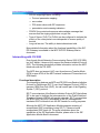
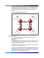
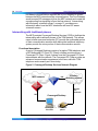
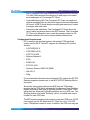
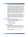
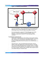
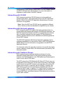
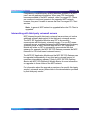
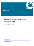
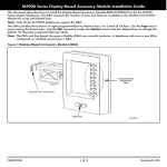
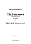
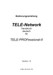
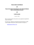
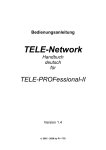
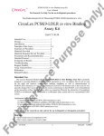
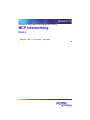
NN10033-111
Succession Multimedia Communications Portfolio
MCP Interworking
Basics
Standard
MCP 1.1 FP1 (02.02)
April 2003
Nortel Networks Confidential
3
Overview
How is this chapter organized
This chapter provides a high-level overview of the interworking
between the Multimedia Communications Platform (MCP) and the
following systems:
•
Primary Rate Interface (PRI)-enabled switches
•
SIP-T-based switches
•
third-party gateways
•
traditional phones
•
third-party voicemail servers
Interworking with PRI-enabled switches
The MCP uses the SIP PRI Gateway to perform interworking with
PRI-enabled switches (switches with PRI interfaces).
For more detailed information about the SIP PRI Gateway, please refer
to the MCP SIP PRI Gateway Basics document.
Functional description
The SIP PRI Gateway is a signaling and media gateway that
interconnects a SIP-based Voice over IP (VoIP) domain and a system
that uses ISDN Primary Rate Interface (PRI/Q.931).
A PRI-enabled system can be a switch that works on the
Public-Switched Telephone Network (PSTN) or Private Branch
Exchange (PBX). The Nortel Networks DMS-100 and the Nortel
Networks Meridian SL-100 are examples of PRI-enabled switches.
The SIP PRI Gateway’s primary function is to convert the packet-based
voice streams of the VoIP system to circuit-based voice streams of the
PRI-enabled system.
Copyright © 2003, Nortel Networks
MCP Interworking Basics
Nortel Networks Confidential
4 Overview
Supported services
The SIP PRI Gateway supports the following call types:
•
SIP to PRI
•
PRI to SIP
•
PRI to PRI
The SIP PRI Gateway supports the following call features:
•
Basic call: The ability to make a call.
•
Hold/Retrieve: The ability to hold and retrieve calls.
•
Call transfers: The ability to forward the call to a third party after the
call is established. Call transfer is limited to SIP clients. Callers from
the PRI-enabled switches cannot perform this function.
•
Call redirect: The ability to forward a call before it is answered.
•
Codec negotiation: The ability to negotiate between different VoIP
codecs during call setup, mid-call, call transfer, and call retrieve.
The SIP PRI Gateway supports the following codecs:
— G.711 mu-law (PCMU)
— G.711 a-law (PCMA)
— G.723.1
— G.729a
•
Call rejection: The ability to reject a call on nodal authentication
request.
•
Calling party name and number: The MCP supports the
delivery/reception of calling party name and number information
to/from PRI-enabled switches. Incoming calling party information
privacy indication is honored by the MCP. For MCP call originations,
privacy indication is not used.
•
Dual-Tone Multi Frequency (DTMF) outpulsing: The ability to
outpulse to PRI-enabled switches. However, DTMF detection is not
provided. Military DTMF digits A-D are currently not supported.
•
ISDN trunk group selection: The selection is based on information
provided in a request Universal Resource Identifier (URI).
•
Ringback: The SIP PRI Gateway provides ringback towards the
circuit-switched side of the network.
•
PRI variant support: The SIP PRI Gateway supports different PRI
variants. For a list of the PRI variants that the SIP PRI Gateway
supports, please refer to the MCP SIP PRI Gateway Basics
document.
NN10033-111 Standard MCP 1.1 FP1 (02.02) April 2003
Copyright © 2003, Nortel Networks
Nortel Networks Confidential
•
Overview 5
SIP/PRI mapping support, including:
— Protocol parameter mapping
— error codes
— PRI cause values with SIP responses
— presentation and screening indicators
•
PRACK: the provisional response acknowledge message that
ensures that the ringing signal does not get lost.
•
Type of Server (ToS): The ToS bit can be configured to indicate the
priority of the voice packet over data packet to ensure quality of
service.
•
Long-call service: The ability to detect abandoned calls.
More detailed information about the functional capabilities of the SIP
PRI Gateway is available in the MCP SIP PRI Gateway Basics
document.
Interworking with CS 2000
Even though Nortel Networks Communication Server 2000 (CS 2000)
is a VoIP switch, it does not fully support the Session Initiation Protocol
(SIP). The following description provides information on how the MCP
interworks with the CS 2000.
The MCP does not support VoIP over Asynchronous Transfer Mode
(ATM) or pure ATM, as the MCP network nodes are IP-based and not
ATM based.
Functional description
The interworking between an MCP and CS 2000 uses Session Initiation
Protocol for Telephones (SIP-T) over User Datagram Protocol (UDP) to
transport ISDN User Part (ISUP), the call control part of the Signaling
System 7 (SS7) protocol.
SIP-T is an extension of the Session Initiation Protocol (SIP) that allows
SIP to be used to facilitate the interconnection of the Public Switched
Telephone Network (PSTN) with packet networks. SIP-T encapsulates
the ISDN User Part (ISUP) messages in the SIP messages and
translates ISUP information into the SIP header for routing purposes.
Although the MCP SIP Application Module supports receiving of
encapsulated ISUP messaging (using SIP-T), it does not send
encapsulated ISUP back out. For more information about the
capabilities of the SIP Application Module, please refer to the SIP
Application Module Basics document.
Copyright © 2003, Nortel Networks
MCP Interworking Basics
Nortel Networks Confidential
6 Overview
Figure 1 shows a network view of the MCP/CS 2000 interconnection.
The MCP configuration enables direct connection between the MCP
and CS 2000 with no intervening SIP proxies. The CS 2000 and its
associated media gateways are placed in the private managed
network.
Figure 1 MCP/CS 2000 Network view
PSTN
network 1
PSTN
network 2
SIP-T
SIP-T
SIP
SIP-T
SIP
SIP
MCP
network 1
MCP
network 2
Supported services
This section provides information on services that can interwork
between the two platforms.
VPN Dialing
A Virtual Private Network (VPN) dial plan enables an enterprise to have
one common dial plan across different geographic locations without
incurring long-distance expenses.
The MCP system uses domains to manage its call routing, while the CS
2000 system uses customer groups.
A profile is used to facilitate call routing between the two systems. The
header named “x-nortel-profile” is used to identify the CS 2000 profile.
The profile is used to map the domain to a PSTN customer group in the
PRODOMAIN table in the Database Module.
NN10033-111 Standard MCP 1.1 FP1 (02.02) April 2003
Copyright © 2003, Nortel Networks
Nortel Networks Confidential
Overview 7
The profile is added when a new domain is created in the MCP system.
Note: The profile name in the TELEPROF table on the CS 2000 side
must match the profile name in the PRODOMAIN table on the MCP
side. Otherwise, interworking between the MCP and CS 2000 will not
work.
Call Forward
Both the MCP and the CS 2000 support call forwarding. No extra
interworking considerations are necessary as call forwarding does not
interact across the MCP and CS 2000 domains, except to deliver a call
between the two domains.
Call Transfer
Call transfer works between the two platforms. The calls are transferred
because from each platforms view the other is just initiating a new call.
Ad Hoc Conference calls
There is no change in the conference application between the two
platforms. When an ad hoc conference call is made, the client
application that starts the conference controls where the conference
bridge is allocated. For example, if the conference call is made from a
client application on the MCP side, the conference bridge will be
allocated on the MCP.
Media Negotiation
The MCP provides media negotiation for the CS 2000 since the CS
2000 gateway controller is not capable of providing this function in the
current release.
The MCP requires a list of all commonly supported codecs across the
CS 2000 media gateways to be provisioned in the cs2k.xml file. The list
is required because the MCP does not determine which gateway the
CS 2000 will use.
Although the MCP also allows for the provisioning of packet times that
the CS 2000 will use, this is not recommended. By provisioning specific
packet times, the SDP packet time will no longer pass transparently
through the MCP. This means that the packet time negotiation that
would normally occur at the client level is now being handled at the
server level, and this could lead to voice connection issues.
The SDP sent by the CS 2000 media gateways is only guaranteed to
contain the v=, c=, m=, and a= SDP headers in the SDP message. The
gateways can accept reception of other SDP parameters, so no
screening needs to be done on the SDP that the MCP sends to the CS
2000. The only exception is the screening of the m= lines to only
Copyright © 2003, Nortel Networks
MCP Interworking Basics
Nortel Networks Confidential
8 Overview
include the audio codecs supported by the gateways. For the SDP that
is received from the CS 2000, the MCP fills in the missing mandatory
parameters as specified in RFC 2327. Details on the restrictions on
SDP are specified in the SN03 IP Gateway InterOP Requirements
document.
Recursive Search
The MCP Back-to-Back User Agent (BBUA) handles SIP 302
responses to an INVITE sent out because of a received INVITE from
the CS 2000. The BBUA sends INVITEs for each contact in the SIP 302
response. The SIP 302 response will not be passed back to the CS
2000. The INVITES for each contact can be sent parallel or sequentially
depending on the mode in which the BBUA processed the initial
INVITE, which then resulted in the SIP 302 response.
Hold
SIP implements a Hold as a re-INVITE with the connection information
in the SDP set to 0.0.0.0. In this release, Hold cannot be handled by all
the CS 2000 media gateways. The MCP shields the CS 2000 from
seeing Hold re-INVITE requests. The MCP, when equipped with an
RTP Media Portal, can manage the RTP connections without affecting
the connection to the CS 2000.
Retrieve
Retrieve is also implemented in SIP through a re-invite. To retrieve a
party on hold the new invite contains valid SDP. The new SDP is used
to restore the media connection between the two clients.
Long Call Audit Timers
In order to prevent hung calls between the two platforms, a long call
audit timer is implemented between the two platforms. Both platforms
use the INFO ping capability described in the SIP INFO message
RFC2976. This involves sending an INFO message with no message
body. Upon receipt of this message, a client should send a 200 OK if
the call exists. If the response to the INFO is any of the following
response codes, then the platform sending the message assumes that
the call no longer exists and frees all resources associated with the call:
•
404 Not Found
•
408 Request Timeout
•
410 Gone
•
480 Temporarily Unavailable
•
481 Transaction Does Not Exist
NN10033-111 Standard MCP 1.1 FP1 (02.02) April 2003
Copyright © 2003, Nortel Networks
Nortel Networks Confidential
Overview 9
If the platform sending the INFO receives a response code other than
the ones listed above, it treats the response as a valid audit response,
and does not bring the call down.
The CS 2000 sends a 200 OK for an empty INFO message and a 481
response code if the call leg does not exist.
Supported media
The following are the media supported by the interworking of MCP and
the CS 2000:
•
G. 711 PCMU
•
G. 711 PCMA
•
G. 729
•
G. 723
•
G3 Fax
•
Modem
Note 1: This list represents a full list of the media capabilities the
MCP can use while interworking with the CS 2000. The actual list of
supported media types depends on the capabilities of the gateways
that the CS 2000 is using.
Note 2: G3 Fax and Modem media calls are used only for CS 2000
gateway calls as there are no MCP endpoints that support either of
these two media types.
QoS
MCP implements its Quality of Service through the DiffServ
(Differentiated Service) feature. The parameters of MCP QoS include
the following:
•
QoS DiffServ code for signaling: specifies signaling quality for SIP
clients.
•
QoS DiffServ code for audio: specifies audio quality for SIP clients.
•
QoS DiffServ code for video: specifies video quality for SIP clients.
•
QoS 802.1p for service priority: specifies service priority for SIP
clients.
Interworking with third-party gateways
The MCP can use SIP signaling between the MCP network and a
third-party SIP-enabled gateway. The third-party gateway provides the
necessary signalling interworking between the MCP network and the
other network to which the gateway is connected. For example, a
Copyright © 2003, Nortel Networks
MCP Interworking Basics
Nortel Networks Confidential
10 Overview
line-based voicemail server requires that a Line Gateway be placed
between the MCP network and the voicemail server. This Line Gateway
would process SIP messages to/from the MCP network and create the
corresponding line signalling to/from the line network. “Interworking
with third-party voicemail servers” on page 13, provides more
information about how the MCP interworks with non-SIP aware
voicemail servers.
Interworking with traditional phones
The MCP provides Converged Desktop Services (CDS) to facilitate the
interworking with traditional phones of the TDM network. This allows
users to have a personal computer (PC) provide the multimedia portion
of their communication session while having the traditional telephony
system provide the voice portion of their communication session.
Functional description
A user’s Converged Desktop consists of a regular TDM telephone, and
a SIP Multimedia PC Client (PC Client) software provisioned as a
Converged PC Client. Figure 2 shows how the Converged PC Client
interconnects with the network. The Converged PC Client provides an
enhanced communication experience to the user, while the TDM
telephone works exactly as it does today.
Figure 2 Converged Desktop Services Network Diagram
MCP network
PRI
Existing
switching system
Various
line
protocols
SIP
Converged Desktop
Converged
PC Client
NN10033-111 Standard MCP 1.1 FP1 (02.02) April 2003
Traditional
phone
Copyright © 2003, Nortel Networks
Nortel Networks Confidential
Overview 11
Converged Desktop Services
CDS enhances the end user’s communication experience in a variety
of ways:
•
Advanced Call Handling: The user can use the MCP Personal
Agent web pages to control the user’s availability. By providing this
ability to CDS users, features not easily accessible on existing TDM
switching systems now become viable. For example, a user can
activate MCP-based forking (using the Personal Agent web pages)
so that when the user’s desktop telephone is called, the users cell
phone rings as well. Once one leg of the forked call is answered, the
other leg stops ringing.
•
Inbound call log: Allows the user to see who has called and when
the call occurred.
•
Video calling line identification: Allows the user to see who is calling.
The picture is retrieved from the network-based address book
accessible on the Converged PC Client.
•
Redirection of incoming calls at the Converged PC Client: Upon the
arrival of an incoming call, the user may click on the “Redirect”
button, and send the incoming call to another address. Once the
user answers the call (using the TDM phone), the redirect function
is no longer available.
•
File transfer: If both the originator and terminator support the MCP
file transfer collaboration application, then files can be transferred
back and forth between the two users. The PC Client (both
Converged and non-Converged) is the only endpoint that supports
this functionality.
•
Whiteboard sharing: If both the originator and terminator support the
MCP whiteboard collaboration application, then a whiteboard
session can be set up between the two users. The PC Client (both
Converged and non-Converged) is the only endpoint that supports
this functionality.
•
Clipboard transfer: If both the originator and terminator support the
MCP clipboard transfer collaboration application, then the Windows
System Clipboard may be transferred between the two users. The
clipboard transfer application allows a user to “Copy (CTRL-C)”
items such as PowerPoint slides or sections of Excel spreadsheets
to the clipboard, and then sends them to the other party. The other
party then “Pastes (CTRL-V)” the items. The PC Client (both
Converged and non-Converged) is the only endpoint that supports
this functionality.
•
Web Co-browsing: If both the originator and terminator are capable
of this functionality, then one user can automatically drive the
other’s web browser. The PC Client (both Converged and
Copyright © 2003, Nortel Networks
MCP Interworking Basics
Nortel Networks Confidential
12 Overview
non-Converged) is the only endpoint that supports this functionality.
The Web Client supports the reception of web pages, but cannot
send web pages to a Converged PC Client.
•
Instant Messaging (IM): The Converged PC Client can send and
receive messages from any client that supports the Nortel Networks
IM format. All MCP clients support sending and receiving of instant
messages with each other.
•
Presence state indications: The Converged PC Client allows the
user to select a presence state in the MCP network. The Converged
PC Client also allows the user to see the presence states for the
Buddies defined in the user’s network-based address book.
Configuration Requirements
PRI is used as the interface between the existing TDM switching
system and the MCP. The MCP supports the following PRI protocol
variants:
•
AT&T 4ESS(AT4)
•
AT&T 5ESS (E10)
•
AT&T TR 41459
•
Bellcore National 2
•
ETSI
•
ECMA-143
•
ETS 300 102-1
•
Northern Telecom DMS-100 (DMS)
•
NIS A211-1
•
QSig
For more detailed information about the which PRI variants the SIP PRI
Gateway supports, please refer to the MCP SIP PRI Gateway Basics
document.
Successful interworking between the MCP and the TDM switch
requires that the TDM switch activate the Simultaneous Ring (SimRing)
feature and assign each user a SimRing number. A user in the TDM
switch that has acquired this SimRing number can be a CDS user. The
SimRing feature must send “SimRing” calls to a routable and unique
number for each CDS user.
The MCP system operator must provision a user as a CDS user. A CDS
user cannot use the SIP Multimedia PC Client for voice. The CDS
user’s TDM phone is used for voice. In addition, the CDS user may use
NN10033-111 Standard MCP 1.1 FP1 (02.02) April 2003
Copyright © 2003, Nortel Networks
Nortel Networks Confidential
Overview 13
other SIP endpoints (such as the SIP Multimedia Web Client or an
i2004 controlled by the IP Client Manager (IPCM) for voice over IP calls.
An MCP alias must be set up for each user so that the alias is the same
as the Calling Line ID sent from the TDM switch to the MCP over PRI.
When a non-CDS MCP user calls a CDS user, the call is sent out the
gateway to the CDS user’s TDM phone and the non-CDS user’s
public/private charge ID is used to identify them to the TDM switch as
the calling party. This charge ID is sent to the Converged PC Client, on
the SimRing leg of the call, and is used by the Converged PC Client to
contact the calling party’s MCP client. Therefore, the non-CDS user’s
charge ID must be included as an alias in the non-CDS user’s
provisioning. A non-CDS user’s charge ID cannot be shared amongst
users within a domain because the charge ID must be included as an
alias and a user's aliases must be unique within a domain.
Calls to a CDS user must terminate to the existing switching system of
the CDS user before the call is routed to the MCP. For example, the
originator’s existing switching system must route calls using the
existing systems, as opposed to sending the call to the MCP. This is
required since all calls from the SIP PRI gateway are implied to have
been triggered by the SimRing feature on the existing switching
system.
Interworking with third-party voicemail servers
There are three major types of third-party voicemail servers. The
following sections describe how the MCP can interwork with the
following types of third-party voicemail servers:
•
SIP-based voicemail servers
•
Trunk-based voicemail servers
•
Line-based voicemail servers
SIP-based voicemail servers
SIP-based voicemail servers are SIP-enabled and can interwork
directly with the MCP network. SIP is used to set up connections
between the client and the voicemail server. The RTP Media Portal is
used to carry the media packets between the client and the voicemail
server.
Figure 3 shows how the MCP interconnects with a SIP-aware
third-party voicemail server.
Copyright © 2003, Nortel Networks
MCP Interworking Basics
Nortel Networks Confidential
14 Overview
Figure 3 SIP-based Voicemail Server
MCP network
UNIStim
SIP
MGCP+
RTP
RTP
For more information on how the SIP Application Module uses Media
Gateway Control Protocol Plus (MGCP+) to control the RTP Media
Portal, please refer to the MCP Media Portal Basics document.
For more information on how the IP Client Manager uses Unified
Networks IP Stimulus (UNIStim) to control the i2004 Internet
Telephone, please refer to the MCP IP Client Manager Basics
document.
Trunk-based voicemail servers
Trunk-based voicemail servers cannot directly communicate with the
MCP network. A SIP PRI Gateway is required for the MCP to interwork
with a trunk-based voicemail server. The SIP PRI Gateway also
provides a media path from the IP network to the voicemail server on
the PSTN.
A terminal server, using a Simplified Message Desktop Interface
(SMDI), sends data regarding the storage and retrieval of voicemail
from the trunk-based voicemail server to the MCP network. The MCP
network does not send data back to the voicemail server over the SMDI
link. Figure 4 shows a network view of the MCP interconnection with a
trunk-based third-party voicemail server.
NN10033-111 Standard MCP 1.1 FP1 (02.02) April 2003
Copyright © 2003, Nortel Networks
Nortel Networks Confidential
Overview 15
Figure 4 Trunk-based Voicemail Server
IP network
SMDI
SMDI
MCP network
SIP
SMDI
PRI
UNIStim
MGCP+
RTP
RTP
Line-based voicemail servers
Line-based voicemail servers cannot directly communicate with the
MCP network. A Line Gateway, also known as an analog station
gateway, is required for the MCP to interwork with a line-based
voicemail server.
Similar to interworking with trunk-based voicemail servers, an SMDI
terminal server is to exchange data between the MCP and the legacy
voicemail server. However, the SMDI links are used to both send and
receive data regarding the storage and retrieval of voicemail from the
line-based voicemail server to the MCP network. Figure 5 shows a
network view of the MCP interconnection with a line-based third-party
voicemail server.
Copyright © 2003, Nortel Networks
MCP Interworking Basics
Nortel Networks Confidential
16 Overview
Figure 5 Line-based Voicemail Server
IP network
SMDI
SMDI
MCP network
SIP
SMDI
UNIStim
MGCP+
RTP
RTP
NN10033-111 Standard MCP 1.1 FP1 (02.02) April 2003
Copyright © 2003, Nortel Networks
Nortel Networks Confidential
17
Upgrades
How this chapter is organized
This chapter provides information about upgrade procedures dealing
with MCP interworking with the following other systems:
•
Primary Rate Interface (PRI)-enabled switches
•
SIP-T-based switches
•
third-party gateways
•
traditional phones
•
third-party voicemail servers
Interworking with PRI-enabled switches
MCP interworking with PRI-enabled switches does not involve
additional software deployment to the PRI-enabled switches. The MCP
SIP PRI Gateway uses standard PRI protocols and is compatible with
any PRI-enabled switch that understands these standard PRI
protocols:
•
AT&T 4ESS(AT4)
•
AT&T 5ESS (E10)
•
AT&T TR 41459
•
Bellcore National 2
•
ETSI
•
ECMA-143
•
ETS 300 102-1
•
Northern Telecom DMS-100 (DMS)
•
NIS A211-1
•
QSig
Because SIP revisions are backwards compatible, the MCP SIP
Application Module and the MCP SIP-PRI Gateway can be upgraded
Copyright © 2003, Nortel Networks
MCP Interworking Basics
Nortel Networks Confidential
18 Upgrades
independently of one another. Refer to MCP SIP PRI Gateway Basics
and MCP SIP Application Module Basics for more information on
upgrades to those nodes of the MCP network.
Interworking with CS 2000
MCP interworking with the CS 2000 does not involve additional
software deployment. The functionality exists in the SIP Application
Module. Refer to the MCP SIP Application Module Basics for more
information on upgrades.
Note: Since the MCP and CS 2000 can be upgraded at different
times, the two products are backwards compatible by one release.
Interworking with third-party gateways
MCP interworking with SIP-enabled third-party gateways does not
involve additional software deployment to the third-party gateways. The
MCP SIP Application Module uses SIP to successfully communicate
with a third-party gateway that also speaks SIP. Each third-party
gateway software release must be validated and certified against the
current MCP release.
The MCP SIP Application Module and third-party gateways can be
upgraded independently of one another. Refer to MCP SIP Application
Module Basics for more information on upgrades to the MCP SIP
Application Module.
For information about the upgrade procedures of a specific third-party
vendor’s gateway, please refer to the documentation provided by that
third-party vendor.
Interworking with Traditional Phones
MCP interworking with traditional telephones does not involve
additional software deployment to the existing switching system.
However, the SimRing feature on the TDM switch must be activated in
order to route calls to CDS users.
The MCP network and SIP Multimedia PC Client (PC Client) may not
be upgraded at the same time. As new CDS functionality is introduced
in the network through MCP network node upgrades, the existing PC
Clients must continue to interwork with the network. Therefore, the
MCP network nodes must be backwards compatible with older PC
Clients and MCP nodes. In addition, PC Clients (both Converged and
non-Converged) must be backwards compatible with all previously
released PC Clients, as different versions of the clients may co-exist in
a given MCP network.
NN10033-111 Standard MCP 1.1 FP1 (02.02) April 2003
Copyright © 2003, Nortel Networks
Nortel Networks Confidential
Upgrades 19
Compatibility is maintained by version identifiers included in an MCP
user’s service package information. When new CDS functionality
becomes available in the MCP network, older Converged PC Clients
can continue to exist and operate in the upgraded MCP network;
however, they won’t be able to access the new Converged PC Client
services.
Note: In general, MCP network is upgraded before the PC Client is
upgraded.
Interworking with third-party voicemail servers
MCP interworking with third-party voicemail servers does not involve
additional software deployment to the third-party voicemail servers.
The MCP SIP Application Module uses SIP to successfully
communicate with third-party voicemail servers. For non-SIP-aware
voicemail servers, a gateway between the MCP network and the legacy
voicemail server is used, in which case the MCP SIP Application
Module still relies on SIP to successfully communicate with that
gateway (for example, the MCP SIP PRI Gateway connects the MCP
network to a PRI trunk-based voicemail server).
The MCP SIP Application Module and the MCP SIP PRI Gateway can
be upgraded independently of any third-party voicemail server (or
necessary intermediary gateway). Refer to MCP SIP PRI Gateway
Basics and MCP SIP Application Module Basics for more information
on upgrades to those nodes of the MCP network.
For information about the upgrade procedures of a specific third-party
vendor’s voicemail server, please refer to the documentation provided
by that third-party vendor.
Copyright © 2003, Nortel Networks
MCP Interworking Basics
20 Upgrades
NN10033-111 Standard MCP 1.1 FP1 (02.02) April 2003
Nortel Networks Confidential
Copyright © 2003, Nortel Networks
Nortel Networks Confidential
21
Fault management
For more information about fault management on a specific MCP
network node, please refer to the Fault Management chapter in the
corresponding documents:
•
MCP SIP Application Module Basics
•
MCP SIP PRI Gateway Basics
For information about CS 2000 fault management functionality, refer to
the CS 2000 Fault Management document.
For information about fault management functionality on any third-party
gateway or voicemail server, please refer to the documentation
provided by that third-party vendor.
Copyright © 2003, Nortel Networks
MCP Interworking Basics
22 Fault management
NN10033-111 Standard MCP 1.1 FP1 (02.02) April 2003
Nortel Networks Confidential
Copyright © 2003, Nortel Networks
Nortel Networks Confidential
23
Configuration Management
How this chapter is organized
This chapter provides information about the tasks required to configure
the MCP to allow interworking with the following other systems:
•
PRI-enabled switches
•
SIP-T-based switches
•
third-party gateways
•
traditional phones
•
third-party voicemail servers
Unless stated otherwise, all tasks are described from the MCP
perspective.
Configuring the MCP SIP PRI gateway
For more information about configuring the MCP SIP PRI Gateway,
please refer to the Configuration Management chapter of the MCP SIP
PRI Gateway Basics and MCP SIP Application Server Basics
documents.
Configuring CS 2000 interworking
This section describes the tasks required to configure the MCP for CS
2000 interworking. This section also describes the key settings required
for the CS 2000 interworking.
Configuration tasks
The configuration uses provisioning tasks that have been described in
detail in the MCP SIP Provisioning Client User Guide. This section
focuses on tasks related to configuring a domain for CS 2000
interworking.
The table below shows the provisioning tasks required depending on
whether a domain exists or not. This section provides procedures for
Copyright © 2003, Nortel Networks
MCP Interworking Basics
Nortel Networks Confidential
24 Configuration Management
tasks required in both scenarios. For other tasks, refer to the MCP SIP
Provisioning Client User Guide.
Table 1 Configuration Tasks for CS 2000 Interworking
Tasks
Domain Exists
Domain Does Not Exist
Login
Yes
Yes
Add Domain
No
Yes
List Domain (for modification)
Yes
No
Assign Services
No
Yes
Create Service Package
No
Yes
Add gateway, gateway route, trunk group
Yes
Yes
Set Class of Service
Yes
Yes
Add Telephony Routes
Yes
Yes
Add Route Lists
Yes
Yes
Set Profile
Yes
Yes
Login requirements
All the tasks are performed by an administrator through the SIP
Provisioning Client.
The administrator requires the following access:
•
Domain Management
•
User Management
•
IPCM Provisioning
•
Gateway Routes
•
Device Management
•
Telephony Routes
•
Service Package Creation
Procedure 1 Access the SIP Provisioning Client
From a web browser,
1
Enter the Uniform Resource Locator (URL) of the SIP
Provisioning Client.
NN10033-111 Standard MCP 1.1 FP1 (02.02) April 2003
Copyright © 2003, Nortel Networks
Nortel Networks Confidential
Configuration Management 25
2
Enter your user name and password.
3
Click LOG IN NOW.
Gateway configuration
The MCP views the CS 2000 as a type of gateway. To complete calls
between the MCP and the CS 2000, gateways, gateway routes, and
virtual trunk groups need to be configured.
Note: A domain must be configured for CS 2000 interworking before
configuring the gateway.
Procedure 2 Configure a gateway for CS 2000 interworking
From the SIP Provisioning Client,
1
Click Gateways after you log in.
2
Click Add Gateway. The system displays Create new gateway
window.
3
Enter the information for a CS 2000 gateway host. The CS 2000
gateway host requires the following information:
•
CS 2000 host name: The name of the server.
•
Port: The port number is 5060.
•
maddr: The IP address of the CS 2000’s Virtual Router
Distribution Node (VRDN).
•
Transport protocol: Identify UDP as the transport protocol.
Example
An example of the gateway host information is shown as
follows:
SIPSERVER:5060;maddr=10.10.10.10;transport=udp
4
Enter cs2k in the Gateway Type field.
5
Click Save to conclude the procedure.
Procedure 3 Configure a gateway route for CS 2000 interworking
From the SIP Provisioning Client,
1
Click Gateways after you log in.
2
Click Add route. The system displays Create new gateway route
window.
Copyright © 2003, Nortel Networks
MCP Interworking Basics
26 Configuration Management
Nortel Networks Confidential
3
Enter a description of the new route in the Description box, for
example, CS 2000.
4
Click the Domain pull-down list and select a domain that is used
for CS 2000 interworking to associate with the route.
5
Click Save to complete the procedure.
For more information about using the SIP Provisioning Client and
configuring gateways, please refer to the MCP SIP Provisioning Client
User Guide and the MCP SIP PRI Gateway Basics documents.
Procedure 4 Configure a trunk group for CS 2000 interworking
From the SIP Provisioning Client,
1
Click Gateways after you log in.
2
Click Add Trunk Group. The system displays the Create new
trunk group window.
3
Select a CS 2000 gateway from the Gateway pull-down list.
4
Select a CS 2000 gateway route from the Route pull-down list.
5
Enter a virtual trunk group name.
6
Click Save to complete the procedure.
For more information about using the SIP Provisioning Client and
configuring virtual trunk groups, please refer to the MCP SIP
Provisioning Client User Guide and the MCP SIP PRI Gateway Basics
documents.
Telephony routes configuration
Telephony routes configuration is required to set up Class of Service
(COS), telephony routes, and route lists for CS 2000 interworking.
Procedure 5 Configure Class of Service for CS 2000 interworking
From the SIP Provisioning Client,
1
Click Domain after you log in.
2
Select the interworking domain you want to configure.
3
Click Telephony Routes and then Routing COS.
4
Enter a name for the Class of Service in the Name box. The
name can be alphanumeric.
5
Enter a description for the COS in the Description box.
6
Click Save. The system displays the newly created COS in the
lower part of the window.
NN10033-111 Standard MCP 1.1 FP1 (02.02) April 2003
Copyright © 2003, Nortel Networks
Nortel Networks Confidential
Configuration Management 27
7
Repeat Step 4-6 to create additional COS values you need.
8
Use the Up and Down buttons to reorder the COS in the Current
Choices Available box. The higher the order, the more services
and priorities the COS has.
For more information about using the SIP Provisioning Client and
configuring COS, please refer to the MCP SIP Provisioning Client User
Guide and the MCP SIP PRI Gateway Basics documents.
Procedure 6 Configure telephony routes for CS 2000
interworking
From the SIP Provisioning Client,
1
Click Domain after you log in.
2
Select the interworking domain you want to configure.
3
Click Telephony Routes and then Add Telephony Route. The
system displays the Create New Telephony Route window.
4
Enter the parameters of the telephony route.
5
Add the route to a route list.
6
Click Save.
7
Repeat Step 3-6 to add more routes.
8
Click List Telephony Routes to display the list of routes created
for CS 2000 interworking.
9
Click Change Parameters. The system displays the parameters
related to the gateway route, including the following:
10
Set the parameters to the appropriate values.
11
Click Save to complete the procedure. You can also click Clear
to remove all the existing values in the fields.
For more information about using the SIP Provisioning Client and
configuring telephony routes, please refer to the MCP SIP Provisioning
Client User Guide and the MCP SIP PRI Gateway Basics documents.
Procedure 7 Configure route lists for CS 2000 interworking
From the SIP Provisioning Client,
1
Click Domain after you log in.
2
Select the CS 2000 domain you want to configure.
3
Click Telephony Routes and then Add Route List.
Copyright © 2003, Nortel Networks
MCP Interworking Basics
28 Configuration Management
4
Nortel Networks Confidential
Click Save to complete the procedure. You can click Clear to
remove all the existing values.
For more information about using the SIP Provisioning Client and
configuring route lists, please refer to the MCP SIP Provisioning Client
User Guide and the MCP SIP PRI Gateway Basics documents.
Configure domain or sub-domain profile
The MCP maps the domains (and sub-domains) of the MCP network to
the route lists/translations of the CS 2000 side, using profile
information. The following procedure configures the header profile for
the domain (or sub-domain) so that MCP knows what domain (or
sub-domain) to use in order to communicate with a CS 2000.
If a sub-domain is used, then the sub-domain data will override the data
in the parent domain.
Procedure 8 Configure domain profile for CS 2000 interworking
From the SIP Provisioning Client,
1
Click Domain after you log in.
2
Select the domain you want to configure to talk to CS 2000.
3
Click Set Profile.
4
Enter a profile name in the Profile field. The profile name must
be the same as the profile name in table TELEPROF in the CS
2000.
5
Click Save to complete the procedure.
Note: The same steps can be used to configure a
sub-domain. After selecting a domain in step 2, click on
Sub-Domain and select Set Profile for the sub-domain.
For more information about using the SIP Provisioning Client and
configuring domain profiles, please refer to the MCP SIP Provisioning
Client User Guide and the MCP SIP PRI Gateway Basics documents.
Node name configuration
The SIP Application Module and CS 2000 use unique names to identify
themselves in the network. Node names must be alpha-numeric strings
and can not contain special characters like "_" or "-". Configuring
service node names is performed through the MCP System
Management Console. For more information on using the Sytem
Management Console, please refer to MCP System Management
Console Basics.
NN10033-111 Standard MCP 1.1 FP1 (02.02) April 2003
Copyright © 2003, Nortel Networks
Nortel Networks Confidential
Configuration Management 29
When the SIP Application Module is deployed from the management
server, the service node name is defined in one of two places,
depending on whether or not the SIP Application Module is configured
in an N+M cluster.
Non-N+M node name configuration
In a non-N+M cluster configuration, the service node name is added to
the "Server Properties" tab in the System Management Console. In a
non-N+M configuration, the service node name can be the node name
of the SIP Application Module platform. For more information on
configuring the SIP Application Module service node name in a
non-N+M configuration, please refer to the Configuration chapter in the
MCP SIP Application Module Basics document.
Once the service node name information is configured in the “Server
Properties” tab of the System Management Console, this information
must then be datafilled on the CS 2000 (table MGCINV).
N+M node name configuration
In an N+M configuration, the service node name has to be assigned to
the service instance so, unlike the non-N+M configuration, the service
node name can not be the node name of the SIP Application Module
platform. Each service instance is defined as a service parameter in
each Network Service Description (NSD) in the “Transport
Management” tab. Each NSD has to define a unique service name.
This is done by adding a service name of "Service_Node_Name" in the
label field and the desired node name in the Value part. For more
information on configuring the SIP Application Module service node
name in a N+M configuration, please refer to the Configuration chapter
in the MCP SIP Application Module Basics document.
Once the service node name information is configured in the “Transport
Management” tab of the System Management Console, this
information must then be datafilled on the CS 2000 (table MGCINV).
CS 2000 node authorization
The SIP Application Module allows only authorized network nodes to
send a SIP request to it with out requiring the request to be
authenticated. The SIP PRI Gateway is an example of an authorized
network node; the SIP Application Module does not challenge incoming
call requests from the SIP PRI Gateway. The CS 2000 node must be
added to list of authorized nodes so that it can send SIP-T messaging
to the SIP Application Module. This is achieved by adding the IP
address of the CS 2000 to the Authorized SIP Nodes field in the
“Authentication” tab of the System Manage Console. For more
information on configuring the SIP Application Module service node
Copyright © 2003, Nortel Networks
MCP Interworking Basics
30 Configuration Management
Nortel Networks Confidential
please refer to the Configuration chapter in the MCP SIP Application
Module Basics document.
Configuring third-party gateway interworking
The provisioning tasks required for the MCP to interwork with
third-party gateways are described in detail in the Gateways chapter of
the MCP SIP Provisioning Client User Guide document.
Configuring traditional phone interworking
Provisioning tasks to configure the MCP to interwork with traditional
phones must be made on both the MCP side and the existing switching
system.
MCP configuration
The provisioning tasks to configure an MCP user as a CDS user are
described in detail in the User Management chapter of the MCP SIP
Provisioning Client User Guide document.
Switching system configuration
This section describes the steps to configure and activate the SimRing
feature on the Nortel Networks DMS family of TDM switches. Please
refer to feature document AJ4934 Simultaneous Ringing for more
information about the functionality provided by SimRing.
For specific information on enabling the SimRing equivalent feature on
third-party switches, please refer to the documentation provided by that
third-party vendor.
Successful interworking between the MCP and the TDM switch
requires that the TDM switch activate the SimRing (or equivalent)
feature and assign each CDS user a SimRing number. The SimRing (or
equivalent) feature sends “SimRing” calls to the routable and unique
number for each CDS user.
Figure 6 shows the conceptual steps required for provisioning the
SimRing (or its equivalent) feature on a TDM switch.
NN10033-111 Standard MCP 1.1 FP1 (02.02) April 2003
Copyright © 2003, Nortel Networks
Nortel Networks Confidential
Configuration Management 31
Figure 6 SimRing configuration procedure flow
Enable
SimRing
on switch
Assign
SimRing
to a line
View
SimRing
status
Enabling SimRing on the DMS
Before adding SimRing to a line, make sure that table OFCENG is
datafilled properly in order for SimRing to work. Sample datafill is
shown below:
>TABLE OFCENG
MACHINES NOT IN SYNC - DMOS NOT ALLOWED JOURNAL FILE UNAVAILABLE
- DMOS NOT ALLOWED
TABLE: OFCENG
>POS SIMRING_RES_CONTROL
SIMRING_RES_CONTROLY N
>POS SIMRING_CENTREX_CONTROL
SIMRING_CENTREX_CONTROLY N
>POS NO_OF_CLONE_TIDS
NO_OF_CLONE_TIDS 20
For detailed engineering information about configuring these OFCENG
tuples correctly, please refer to the North American DMS-100
Translations Guide Volume 17 of 20 (Document Number:
297-8001-350).
Assigning SimRing on a DMS line
To assign SimRing to an existing line, use the EST (establish)
command of SERVORD.
>SERVORD
SO:
>EST
SONUMBER:
NOW
0
>$
GROUPTYPE:
>SIMRING
SIMRING_PILOT_LEN:
>HOST 0 1 10 5
SIMRING_MEMBER_DN:
>6215115
SIMRING_MEMBER_DN:
>6215010
SIMRING_MEMBER_DN:
>$
SIMR_STATE: INACT
Copyright © 2003, Nortel Networks
8 16 PM
MCP Interworking Basics
32 Configuration Management
Nortel Networks Confidential
>ACT
SIMR_PIN:
>123
Viewing DMS SimRing information
In order to see if a user has SimRing active, the line must be queried
using SERVORD. Use the QLEN (Query LEN) or QDN (Query DN)
commands:
>QLEN 6212064
-----------------------------------------------------------------------------LEN:
HOST 00 1 10 05
TYPE: SINGLE PARTY LINE
SNPA: 613
DIRECTORY NUMBER:
6212064
LINE CLASS CODE: IBN
IBN TYPE: STATION
CUSTGRP:
IBNTST
SUBGRP: 0 NCOS: 0
SIGNALLING TYPE: DIGITONE
CARDCODE: 6X17AA
GND: N PADGRP: STDLN BNV: NL MNO: N
PM NODE NUMBER
:
41
PM TERMINAL NUMBER :
326
OPTIONS:
DGT SIMRING 0 ACT $
OFFICE OPTIONS:
AIN LNPOFFICE
SimRing has its own command for viewing its properties. Use the
command QSIMR (query SimRing) on a DN to display the set-up of
SimRing on the line:
>QSIMR 6212064
-----------------------------------------------------------------------------Pilot DN: 6136212064
Pilot LEN: HOST 00 1 10 05
The SimRing feature is ACT
Member DN 1 - 6215115
Member DN 2 - 6215010
To query the feature using Table Control, go through table IBNFEAT.
Once in the table, position on the LEN, the NCOS, and the feature:
>TABLE IBNFEAT
JOURNAL FILE UNAVAILABLE - DMOS NOT ALLOWED
TABLE: IBNFEAT
>POS 00 1 10 05 0 SIMRING
HOST 00 1 10 05
0
SIMRING
SIMRING
0
NN10033-111 Standard MCP 1.1 FP1 (02.02) April 2003
ACT
$
Copyright © 2003, Nortel Networks
Nortel Networks Confidential
Configuration Management 33
In order to view the member DNs of the SimRing group, go to table
PILOTGRP and position on the pilot's group key (located in the QDN
output):
>TABLE PILOTGRP
MACHINES NOT IN SYNC - DMOS NOT ALLOWED
JOURNAL FILE UNAVAILABLE - DMOS NOT ALLOWED
TABLE: PILOTGRP
>POS 0
0
(6215115) (6215010)$
Configuring third-party voicemail server interworking
The tasks required to configure the MCP for interworking with a
voicemail server can vary, depending on the type of voicemail server.
The MCP can be configured to interwork with the following types of
voicemail servers:
•
SIP-based
•
trunk-based
•
line-based
The provisioning tasks required for the MCP to interwork with each type
of the above voicemail servers are described in detail in the Voice Mail
Servers chapter of the MCP SIP Provisioning Client User Guide
document.
Copyright © 2003, Nortel Networks
MCP Interworking Basics
34 Configuration Management
NN10033-111 Standard MCP 1.1 FP1 (02.02) April 2003
Nortel Networks Confidential
Copyright © 2003, Nortel Networks
Nortel Networks Confidential
35
Accounting management
For more information about accounting functionality on a specific MCP
network node, please refer to the Accounting chapter in the
corresponding documents:
•
MCP SIP Application Module Basics
•
MCP SIP PRI Gateway Basics
The MCP provides both the public and private charge IDs to the SIP
PRI Gateway. For information on configuring the charge IDs for a user,
please refer to the MCP SIP Provisioning Client User Guide. For more
information on how the charge IDs are used, please refer to the MCP
Accounting Module Basics document.
For information about CS 2000 accounting functionality, please refer to
the CS 2000 Accounting document.
For information about accounting functionality on any third-party
gateway or voicemail server, please refer to the documentation
provided by that third-party vendor.
Copyright © 2003, Nortel Networks
MCP Interworking Basics
36 Accounting management
NN10033-111 Standard MCP 1.1 FP1 (02.02) April 2003
Nortel Networks Confidential
Copyright © 2003, Nortel Networks
Nortel Networks Confidential
37
Performance management
For more information about performance management functionality on
a specific MCP network node, please refer to the Performance
Management chapter in the corresponding documents:
•
MCP SIP Application Module Basics
•
MCP SIP PRI Gateway Basics
For information about CS 2000 performance management functionality,
please refer to the CS 2000 Performance Management document.
For information about performance management functionality on any
third-party gateway or voicemail server, please refer to the
documentation provided by that third-party vendor.
Copyright © 2003, Nortel Networks
MCP Interworking Basics
38 Performance management
NN10033-111 Standard MCP 1.1 FP1 (02.02) April 2003
Nortel Networks Confidential
Copyright © 2003, Nortel Networks
Nortel Networks Confidential
39
Security and Administration
For more information about security and administration functionality on
a specific MCP network node, please refer to the Security and
Administration chapter in the corresponding documents:
•
MCP SIP Application Module Basics
•
MCP SIP PRI Gateway Basics
For information about CS 2000 security and administration
functionality, please refer to the CS 2000 Security and Administration
document.
For information about security and administration functionality on any
third-party gateway or voicemail server, please refer to the
documentation provided by that third-party vendor.
Copyright © 2003, Nortel Networks
MCP Interworking Basics
40 Security and Administration
NN10033-111 Standard MCP 1.1 FP1 (02.02) April 2003
Nortel Networks Confidential
Copyright © 2003, Nortel Networks
Succession Multimedia Communications Portfolio
MCP Interworking
Basics
Copyright © 2003 Nortel Networks,
All Rights Reserved
NORTEL NETWORKS CONFIDENTIAL:
The information contained in this document is the
property of Nortel Networks. Except as specifically authorized in writing by Nortel Networks, the holder of
this document shall keep the information contained herein confidential and shall protect same in whole or in
part from disclosure and dissemination to third parties and use same for evaluation, operation, and maintenance purposes only. Changes or modifications to the MCP Interworking Basics document without the
express consent of Nortel Networks may void its warranty and void the user’s authority to operate the equipment.
Information is subject to change without notice. Nortel Networks reserves the right to make changes in
design or components as progress in engineering and manufacturing may warrant.
*Nortel Networks, the Nortel Networks logo, the Globemark, UNIStim, MCP, Nortel, Northern Telecom, and
NT, are trademarks of Nortel Networks.
Publication number: NN10033-111
Product release: MCP 1.1 FP1 Standard
Document release: Standard MCP 1.1 FP1 (02.02)
Date: April 2003
Printed in the United States of America.