1
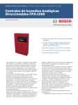
MACURCO INC.
CONTROLLERS & CARBON MONOXIDE DETECTORS
SS103-3A, SS103-10A
SS102H, SS102HC-1
INSTALLATION & OPERATING INSTRUCTIONS
WWW.MACURCO.COM
NOTE:
SUGGESTED WIRE SIZE VS LENGTH OF WIRE BETWEEN EACH SENSOR & CONTROL PANEL
SIZE
MAXIMUM DISTANCE
#18
#16
#14
500 feet
800 feet
1250 feet
GENERAL INFORMATION
All equipment manufactured by Macurco is thoroughly tested and calibrated before leaving the factory. There is no need to
re-calibrate the detectors after installation. The equipment is designed to be fully operational after all wiring is completed. For more
technical and wiring information please refer to the Automatic Exhaust Fan Controllers For Parking Garages & Carbon Monoxide
Transducers data sheets.
LOCATION
Please refer to the attached data sheet titled “Carbon Monoxide System Layouts in Parking Garages”
SS102H & SS102HC-1 GENERAL INFORMATION
The SS102H is partially housed in a plastic case, which mounts on and becomes the cover of, a standard 4SD electrical box
(provided by the installer).
The SS102HC-1 is housed in a plastic case that is attached to a 4x4 plaster ring. It mounts on any four inch square
electrical box.
A low voltage, four conductor, #18 (or larger) cable connects each SS102H, or SS102HC-1 sensor to the SS103 control
panel. There must be an individual cable between each sensor and its control panel group of four terminals. These terminals are
labeled on the sensor cover adjacent to the terminal strip. Set up color coding so that the cable will match the same terminals at the
sensor and control panel. The SS102HC-1 has four pigtail leads: two red for power and a white and black for output. There is an
internal switch in the SS102HC-1 located on the printed circuit board that must be set to volts.
SS102H SENSOR OPERATION
The SS102H sensors have two lights: one green and one red. The green light is a pilot light showing the unit is on and
operational. When power is first applied to the unit, the green light will be off for 1 1/2 minutes while the sensor goes through a
warm-up cycle. After this 1 1/2 minute delay, the green light will be on continuously.
The red light, which is normally off, is part of a supervisory circuit that monitors critical functions of the unit. A failure in
the sensor is shown by a lighted red light, and at the same time a full range (about 4.8 volts) output on terminal A, to actuate relays
in the control panel.
The SS102H was factory calibrated, and cannot be re-calibrated on site. A functional test can be performed by holding a lit
cigarette (a good source of carbon monoxide) under the SS102H, so smoke drifts up through the sensor. This will cause the SS102H
to produce an output voltage to actuate the SS103 control panel. If the installation is in a parking garage, a gasoline powered vehicle
can be operated near the sensor to provide a system test. See the Carbon Monoxide Transducers data sheet for more technical
information.
Although the SS102H is usable within a few minutes of being turned on, it will not reach its calibrated level for about 1
week. The SS102H must be continuously powered.
1
MACURCO CONTROLLERS & DETECTORS (CONT.)
SS102HC-1 SENSOR OPERATION
The SS102HC-1 is a microcomputer controlled sensor. It has a 2 1/2 minute warm up cycle, during which its outputs
progressively increase from 1.0 to 2.1 volts. The internal switch must be set to volts. The green LED type light turns on and off
during the 2 1/2 minute warm up cycle. At the end of the warm up cycle, the light switches to a steady on, to indicate normal
operation. See the Carbon Monoxide Transducers data sheet for more technical information.
The SS102HC-1 is supervised. Various critical operating parameters are measured and any problems are indicated by the
green light turning off and the output going to a high voltage (about 2.9v), to cause the control panel to actuate the exhaust fan.
STABILIZATION TIME
Although the units will be fully operational within a few minutes of being first powered, the SS102H gas sensor requires up
to 7 days to reach its final operating point and the SS102HC-1 up to 3 days. The unit is intended to be continuously powered.
SENSOR POISONS
The gas sensing tip in the detector is designed with extreme sensitivity to the environment. As a result, the sensing
function of the tip may be deteriorated if it is exposed to a direct spray from aerosols such as paints, silicone vapors, etc., or to a high
density of corrosive gases (such as hydrogen sulfide, sulfur dioxide) for an extended period of time.
SERVICING OF UNIT
The SS102H & SS102HC-1 do not require regular maintenance. The units use a self purging semi-conductor sensor that
has a 7-10 year life expectancy. All maintenance and repair of products manufactured by Macurco, Inc. are to be performed at the
Macurco manufacturing facility. Macurco does not sanction any third-party repair facilities.
SS103-3A & SS103-10A GENERAL INFORMATION
The SS103-3A Controller supplies all power to, and receives information from up to three SS102H or SS102HC-1 Carbon
Monoxide Sensors. The panel can control three fans or two fans and one alarm circuit.
The SS103-10A Controller supplies all power to, and receives information from up to ten SS102H or SS102HC-1 Carbon
Monoxide Sensors. The panel can control three fans, or two fans and one alarm circuit.
Please refer to the Automatic Exhaust Fan Controllers For Parking Garages data sheet for more technical and wiring
information.
SS103 INSTALLATION
Mount the SS103 panel in the desired location. Knock out (SS103-3A) or drill (SS103-10A) conduit access holes in bottom
of the case for the 120VAC power, sensor cables and fan control cable. The sensor connections are in the upper center of the panel.
The power connections are in the lower right corner and the fan connections in the lower left corner.
When the SS103-3A is opened, so the cover of the knock out box is to the left, remove the two small screws on the right
side of the inner panel ONLY. Lift the right side, and the inner panel hinges to allow access to the circuit board. On the SS10310A, loosen the two clamping screws on the right side of the unit to gain access to the circuit board.
The 120 VAC power for both the SS103-3A & 10A systems requires less than two amps. Match the cable from the relay
contacts to the size of the load. The maximum power that the relays can switch is 10 Amps at 240 VAC.
The sensors are low voltage (12V) and low voltage cable (4 conductor #18 or larger) can be used, with or without conduit.
SS103 WIRING
All connections are clearly labeled. Each group of four terminals (A, B, C & D) connects to one SS102H or SS102HC-1
sensor. Each zone numbered (1 to 10) matches the front panel designation. For the SS102H set up color coding for the wires to
make sure that terminal designations match: A to A, B to B, C to C & D to D. On the SS102HC-1 the two Red wires go to the C &
D terminals on the SS103 control panel, the White wire goes to terminal A, and the Black wire goes to terminal B.
The Fan control relays are normally de-energized. They energize to turn on the fans. Only the normally open and common
relay contacts are connected to the terminal strip. Therefore, Fan relays in two or more SS103 panels can be connected in parallel to
control the same Fan. WARNING: a magnetic starter will be needed to control the fan motors. The SS103 relays are for pilot duty
only.
2
MACURCO CONTROLLERS & DETECTORS (CONT.)
SS103 OPERATION
START-UP
Turn the FAN sensitivity level pots to the center of their ranges. When power is first applied to the SS103, only the Green
“POWER” light should be on. If SS102HC-1 sensors are used, the appropriate green SENSOR lights on the SS103 will be on, and
One or more FAN circuits may turn on as the SS102HC-1 goes through its self test cycle, which provides an increasing voltage
during the warm up cycle. After one and one half minutes, the SS102H sensors will complete their warm-ups, and all SS102
“SENSOR” green lights should be on. (If not all zones are used on the SS103-3A &-10A only those appropriate green lights will be
on). These SS103 green lights show the sensors are on and in normal operation, and that the wiring between the sensor and control
panel is OK. The SS102HC-1 has a 2 1/2 minute warm-up cycle, during which the output voltage progressively increases from 1.0
to 2.1 volts, which will cause the appropriate SS103 zone lights to actuate.
Some or all of the Red “SENSOR” lights on the SS103-10A panel may be on at this time. These red lights show when a
sensor output reaches the level of carbon monoxide to actuate FAN1, FAN2 or FAN3/ALARM. At the same time a SENSOR Red
light turns on, the amber FAN light or lights start to flash on and off. If the level of CO is high enough, the Red ALARM light also
will flash on and off. Flashing lights indicate that the time delays before relay turn on has been activated.
The SS103-3A has multi-colored lights to show sensor status. They will be off on zones to which no sensors are connected.
Normal operation and clean air is shown by a green sensor light. The light turns amber when “FAN 1” is actuated, then turns red
when “FAN 2” is exceeded. The ALARM relay is delayed, by the ALARM DELAY setting, from the FAN 2 level setting.
Allow the system to stabilize for 10 or 20 minutes. All SENSOR red lights, the FAN amber lights, and the red ALARM
lights should be off once the sensors have warmed up, and the air has been cleared out by the fans.
SS103-10A
For the SS103-10A, from the time a “SENSOR” red light turns on, at which time the amber FAN light starts to flash on and
off, there is a two minute delay before the fan relay is actuated, as shown by a continuous FAN light. Any of the SENSOR red lights
turn on whenever the Fan sensitivity setting is exceeded at any sensors location. Should the Carbon Monoxide level continue to rise,
FAN 2 on the SS103-10A will turn on, then the FAN3/ALARM will turn on. At first, the red FAN3/ALARM light flashes on and
off during the delay period, then turns on steady as the relay closes to actuate the alarm circuit.
SS103-3A
The SS103-3A differs in operation in that it has a shorter delay (30 seconds) FAN on and a short (15 second) FAN turn off
delay. Also, the ALARM range is adjustable continuously from 3 to 33 minutes. This ALARM relay is delayed from the FAN 2
turn on set point.
The unit uses 10Amp field replaceable Autofuses on the three output relay circuits to protect them.
TESTING THE SYSTEM
The best way to functionally test the systems is to run a car (the older and smog producing the better) near each sensor and
observe system operation. Make sure the SS103 potentiometers are set in reasonable ranges: The Fans between 50 and 150 and the
Alarm at 200 or less.
SS102H
Functionally test the system by introducing Carbon Monoxide gas into each sensor, while watching for each SS103
SENSOR red light to turn on. A convenient source of CO is cigarette smoke. Hold a lighted cigarette under each sensor, for several
minutes, so the smoke drifts up through the sensor. Gas from an unlit butane cigarette lighter can also be used to test the system.
Shoot the gas into the holes near the lights of the case. If the job specifications require actual CO testing, the SS102HC-1 sensors
should be used.
SS102HC-1
A switch inside the sensor is labeled TEST. Pushing this switch once puts the sensor into a 2 1/2 minute test mode where it
steps from 1.0 to 2.1 volts. This progressive increase in voltage will cause the SS103 control panel to turn on Fan and Alarm relays
accordingly. The SS102HC-1 optional Field Calibration Kit (FCK), which includes a cylinder of 50 ppm carbon monoxide gas, can
be used to test the SS102HC-1 sensors. If the job requires actual CO testing, other cylinders of gas at other levels can be purchased,
and used with the FCK.
3
MACURCO CONTROLLERS & DETECTORS (CONT.)
SETTING THE CONTROLS
If your installation has no pre-determined Fan and Alarm set points, Macurco makes the following suggestions: Set the
FAN 1 level 50% higher than the average time weighted average of carbon monoxide (CO), usually 50 ppm, that is desired in the
facility. This will be a FAN 1 setting of 75.
Set the SS103-10A FAN 2 level 50% higher than FAN 1, or about 112 ppm
Set the SS103-3A FAN 2 and the SS103-10A ALARM to 200ppm. Set both Alarm Delays to about 30 minutes.
NOTE: Do not set the SS103-10A ALARM higher than 200 ppm when using SS102HC-1 sensors.
If the Alarm relay is used to operate a fan, Macurco suggests that the Time Delay be set to about 3 minutes, and on the
SS103-10A, the ALARM level be set to 50% higher than the FAN 2 or about 170.
ALARM DELAY PROGRAMMING: SS103-10A
Set the ALARM adjustment pot to the desired STEL (Short Term Exposure Limit). Usually, this is the Uniform Building
Code (UBC) standard of 200 ppm. (OSHA suggests using a 200 ppm CEILING, but currently has no standard for STEL for carbon
monoxide.) To set the Alarm delay on the SS103-10A use the four section programming switch, which is located on the printed
circuit board near the fan and alarm relays. A chart inside the cover of the case shows the settings for popular delays. Figure 1
shows more settings.
Figure 1.
ON
OFF
1
2 3 4
50 min.
1
2 3 4
44 min.
1
2
3 4
35 min.
1 2 3 4
25 min.
1
2 3 4
8 min.
1
2 3 4
15 sec.
NOTE: If using SS102HC-1 sensors, do not set the Alarm above 200.
ALARM ACTION
If an alarm is used, a procedure should be set up in the facilities emergency response procedures for what action to take
when the alarm occurs. Consider the following in making those decisions:
The Carbon Monoxide levels of 50 ppm averaged over 8 hours and 200 ppm for some time period, are based on full shift
exposures of workers. This usually does not happen in parking garages, where most people are there for only a few minutes.
Unless there are full time workers in the facility, Macurco suggests that CO alarms be not considered as life threatening
emergencies. Instead use them as advisories to check that all control system components are operating OK.
For the SS102H, in addition to Carbon Monoxide, this system will actuate on smoke and various gases such as gasoline
fumes, propane, alcohol and other combustible vapors.
LIMITED WARRANTY
The SS102H, SS102HC-1, SS103-3A, and SS103-10A gas detectors are warranted to be free from defective material and
workmanship for a period of one (1) year from the date of installation. If any component becomes defective during the warranty
period, it will be replaced or repaired free of charge, if the unit is returned in accordance with the instructions below. This warranty
does not apply to units that have been altered or had repair attempted, or that have been subjected to abuse, accidental or otherwise.
The above warranty is in lieu of all other express warranties, obligations or liabilities. THE IMPLIED WARRANTIES OF
MERCHANTABILITY AND FITNESS FOR PARTICULAR PURPOSE ARE LIMITED TO A PERIOD OF ONE (1) YEAR FROM
THE PURCHASE DATE. Macurco shall not be liable for any incidental or consequential damages for breach of this or any other
warranty express or implied arising out of or related to the use of said gas detector. Manufacturer or its agent’s liability shall be
limited to replacement or repair as set forth above. Buyer’s sole and exclusive remedies are return of the goods and repayment of the
price, or repair and replacement of non-conforming goods or parts. (The Uniform Commercial Code applicable in the State of
Colorado shall govern.)
RETURN INSTRUCTIONS
Call (303) 781-4062 for a Return Authorization number. Then carefully pack the gas detector with a written description of
the nature of the return. Send the unit to the following address:
Macurco Inc.
3946 South Mariposa Street
4
Englewood, Colorado 80110
WWW.MACURCO.COM
REV. 2/99
5