1
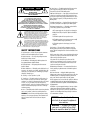
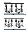
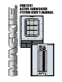
SWA1501
ACTIVE SUBWOOFER
SYSTEM USER’S MANUAL
ACTIVE
LIMIT
SIGNAL
THERMAL
PARALLEL
THRU
(FULL RANGE OUTPUT)
SUBWOOFER
CONTROL
FULL RANGE
INPUT
POWER
HIGH PASS
(MID/HIGH FREQ)
OUTPUT
NORMAL
120Hz
L
L
SUBWOOFER
LEVEL
IN
OUT
R
NORMAL
R
REV 180
PHASE
POWER
ON
SWA1501
ACTIVE SUBWOOFER
115V-AC FUSE AC125V-T6.3A
CONCEIVED AND DESIGNED BY MACKIE DESIGNS INC, WOODINVILLE, WA, USA AND MACKIE EUROPE
• MADE IN ITALY • COPYRIGHT ©2000 • THE FOLLOWING ARE TRADEMARKS OR REGISTERED
TRADEMARKS OF MACKIE DESIGNS INC.: "MACKIE", AND THE "RUNNING MAN" FIGURE • PATENT PENDING
CAUTION
AVIS
RISK OF ELECTRIC SHOCK
DO NOT OPEN
RISQUE DE CHOC ELECTRIQUE
NE PAS OUVRIR
CAUTION: TO REDUCE THE RISK OF ELECTRIC SHOCK
DO NOT REMOVE COVER (OR BACK)
NO USER-SERVICEABLE PARTS INSIDE
REFER SERVICING TO QUALIFIED PERSONNEL
ATTENTION: POUR EVITER LES RISQUES DE CHOC
ELECTRIQUE, NE PAS ENLEVER LE COUVERCLE. AUCUN
ENTRETIEN DE PIECES INTERIEURES PAR L'USAGER. CONFIER
L'ENTRETIEN AU PERSONNEL QUALIFIE.
AVIS: POUR EVITER LES RISQUES D'INCENDIE OU
D'ELECTROCUTION, N'EXPOSEZ PAS CET ARTICLE
A LA PLUIE OU A L'HUMIDITE
The lightning flash with arrowhead symbol within an equilateral
triangle is intended to alert the user to the presence of uninsulated
"dangerous voltage" within the product's enclosure that may be
of sufficient magnitude to constitute a risk of electric shock to persons.
Le symbole éclair avec point de flèche à l'intérieur d'un triangle
équilatéral est utilisé pour alerter l'utilisateur de la présence à
l'intérieur du coffret de "voltage dangereux" non isolé d'ampleur
suffisante pour constituer un risque d'éléctrocution.
The exclamation point within an equilateral triangle is intended to
alert the user of the presence of important operating and maintenance
(servicing) instructions in the literature accompanying the appliance.
Le point d'exclamation à l'intérieur d'un triangle équilatéral est
employé pour alerter les utilisateurs de la présence d'instructions
importantes pour le fonctionnement et l'entretien (service) dans le
livret d'instruction accompagnant l'appareil.
SAFETY INSTRUCTIONS
1. Read Instructions — All the safety and operation instructions
should be read before this Mackie product is operated.
2. Retain Instructions — The safety and operating instructions
should be kept for future reference.
3. Heed Warnings — All warnings on this Mackie product and in
these operating instructions should be followed.
4. Follow Instructions — All operating and other instructions
should be followed.
5. Water and Moisture — This Mackie product should not be used
near water – for example, near a bathtub, washbowl, kitchen sink,
laundry tub, in a wet basement, near a swimming pool, swamp or
salivating St. Bernard dog, etc.
6. Cleaning — Clean only with a dry cloth.
7. Ventilation — This Mackie product should be situated so
that its location or position does not interfere with its proper
ventilation. For example, the Component should not be situated
on a bed, sofa, rug, or similar surface that may block any
ventilation openings, or placed in a built-in installation such as a
bookcase or cabinet that may impede the flow of air through
ventilation openings.
8. Heat — This Mackie product should be situated away from heat
sources such as radiators, or other devices which produce heat.
WARNING: The heat sink may reach high temperatures during
standard use. To ensure proper operation, allow a minimum of six
inches of clearance from the heat sink surface and adequate
ventilation.
2
9. Power Sources — This Mackie product should be connected to a
power supply only of the type described in these operation
instructions or as marked on this Mackie product.
10. Power Cord Protection — Power supply cords should be routed
so that they are not likely to be walked upon or pinched by items
placed upon or against them, paying particular attention to cords at
plugs, convenience receptacles, and the point where they exit this
Mackie product.
11. Object and Liquid Entry — Care should be taken so that objects
do not fall on, and liquids are not spilled into, this Mackie product.
12. Damage Requiring Service — This Mackie product should be
serviced only by qualified service personnel when:
A. The power-supply cord or the plug has been damaged; or
B. Objects have fallen, or liquid has spilled into this Mackie
product; or
C. This Mackie product has been exposed to rain; or
D. This Mackie product does not appear to operate normally
or exhibits a marked change in performance; or
E. This Mackie product has been dropped, or its chassis
damaged.
13. Servicing — The user should not attempt to service this
Mackie product beyond those means described in this operating
manual. All other servicing should be referred to the Mackie Service
Department.
14. To prevent electric shock, do not use this polarized plug with an
extension cord, receptacle or other outlet unless the blades can be
fully inserted to prevent blade exposure.
Pour prévenir les chocs électriques ne pas utiliser cette fiche
polariseé avec un prolongateur, un prise de courant ou une autre
sortie de courant, sauf si les lames peuvent être insérées à fond
sans laisser aucune pariie à découvert.
15. Grounding or Polarization — Precautions should be taken so
that the grounding or polarization means of this Mackie product is
not defeated.
16. Power Precaution — Unplug this Mackie product during
lightning storms or when unused for long periods of time. Note that
this Mackie product is not completely disconnected from the AC
mains service when the power switch is in the OFF position.
17. This apparatus does not exceed the Class A/Class B (whichever
is applicable) limits for radio noise emissions from digital apparatus as
set out in the radio interference regulations of the Canadian Department
of Communications.
ATTENTION —Le présent appareil numérique n’émet pas de bruits
radioélectriques dépassant las limites applicables aux appareils
numériques de class A/de class B (selon le cas) prescrites dans le
règlement sur le brouillage radioélectrique édicté par les ministere
des communications du Canada.
WARNING — To reduce the risk of fire or
electric shock, do not expose this appliance to
rain or moisture.
WARNING — The cabinet has no rigging
points and is not suitable for flying. Never
attempt to suspend the cabinet by its handles.
Lend Me Your Ears
Exposure to extremely
high noise levels may cause
permanent hearing loss. Individuals vary considerably
in susceptibility to noiseinduced hearing loss, but nearly everyone will
lose some hearing if exposed to sufficiently intense noise for a period of time. The U.S.
Government’s Occupational Safety and Health
Administration (OSHA) has specified the permissible noise level exposures shown in this
chart.
According to OSHA, any exposure in excess
of these permissible limits could result in some
hearing loss. To ensure against potentially
dangerous exposure to high sound-pressure
levels, it is recommended that all persons
exposed to equipment capable of producing
these levels use hearing protectors while this
unit is in operation. Ear plugs or protectors in
the ear canals or over the ears must be worn
when operating this amplification system in
order to prevent a permanent hearing loss if
exposure is in excess of the limits set forth here.
Duration Per Day Sound Level dBA, Typical
In Hours
Slow Response
Example
8
6
4
3
2
1.5
1
0.5
0.25 or less
90
92
95
97
100
102
105
110
115
Duo in small club
Subway Train
Very loud classical music
The SWA1501
can produce a
maximum SPL of
128 dB @ 1m
Patrice screaming at Ron about deadlines
Loudest parts at a rock concert
CONTENTS
Lend Me Your Ears ................................................... 3
INTRODUCTION ....................................................... 3
REAR PANEL DESCRIPTION .................................... 4
HOOKUP DIAGRAMS ............................................... 5
CONNECTIONS........................................................ 6
PLACEMENT ............................................................ 6
AC POWER .............................................................. 7
THERMAL CONSIDERATIONS .................................. 7
SERVICE INFORMATION .......................................... 7
Warranty Service ............................................... 7
Troubleshooting ................................................. 7
Repair ............................................................... 9
SWA1501 SPECIFICATIONS ................................... 10
Architect’s and Engineer’s Specifications ......... 10
Frequency Response ....................................... 11
Dimensions ..................................................... 11
INTRODUCTION
Thank you for choosing Mackie Designs’
active sound reinforcement speaker systems.
The SWA1501 is a high output active
subwoofer system. It features a high-precision
15˝ transducer combined with applicationspecific amplifier technology. The system is
composed of a single, compact subwoofer cabinet
with built-in control and amplifier electronics.
Connecting and setting up the SWA1501 is
a breeze. It accepts a stereo or mono line-level
signal via female XLR input jacks. Male XLR
Thru jacks are provided for daisy-chaining the
signal to additional SWA1501 cabinets. The
built-in crossover separates the low frequencies
from the high frequencies, and routes the high
frequencies to the male XLR high-pass output
jacks. Connect these to the inputs of full-range
active speakers such as the Mackie Designs
SRM450s, or to an amplifier powering a pair of
passive speakers such as the combination of
Mackie Designs M•1400i and C300s. A Phase
switch gives you the option of reversing the
polarity of the signal to the subwoofer by 180º.
A Subwoofer Level control allows you to adjust
the balance between the subwoofer and the fullrange speakers.
The built-in amplifier produces 500 watts of
continuous power. The amplifier module sits on
a heatsink that eliminates the need for fans,
dramatically extending life expectancy, and
eliminating maintenance cycles. A tremendous
benefit of having the amplifier located within
the subwoofer cabinet is that the SWA1501
functions as a system, optimizing acoustic, electronic, and mechanical designs to achieve the
highest level of performance and value.
The cabinet is constructed with 15mm thick
multi-layered birch plywood. Carrying handles
are integrated into each side for easy loading
and transport.
Don’t forget to visit our website at www.mackie.com
for more information about this and other Mackie products.
Part No. 030068 Rev. B 01/03
©2003 Mackie Designs Inc. All Rights Reserved.
3
REAR PANEL DESCRIPTION
POWER Switch
Use this switch to turn the SWA1501 on
and off. Make sure the signal source’s level
control is turned down before you turn it on.
AC power supply, this indicator lights green
to let you know that you’re ready to rock
and roll. The cool blue LED on the front of
the cabinet works in the same way.
FULL RANGE INPUT
AC Receptacle
This is where you connect the AC linecord to provide AC power to the SWA1501’s
built-in power amplifiers. Plug the linecord
into an AC socket properly configured for
your particular model.
LIMIT Indicator
The SWA1501 has a built-in limiter that
prevents the amplifier outputs from
overdriving the transducers. The LIMIT indicator lights when the limiter is activated.
It’s okay for the LIMIT indicator to blink occasionally, but if it blinks frequently or
lights continuously, turn down the level
control until the LIMIT indicator only blinks
occasionally.
SIGNAL Present Indicator
This LED illuminates whenever there is
a signal present at the FULL RANGE INPUT
connector on the rear panel.
THERMAL Indicator
The SWA1501 has a thermal protection
circuit that monitors the internal temperature of the amplifiers and heatsink. If the
internal temperature should exceed a safe
operating level, this indicator lights and the
signal is muted to allow the amplifier to cool.
When the temperature cools to a safe level
once again, the thermal protection circuit
deactivates and normal operation continues.
Note: Activation of the thermal protection
circuit is an indication that you should take
steps to avoid continued thermal problems.
See “Thermal Considerations” on page 7.
These are female XLR-type connectors
that accept a balanced line-level signal from
a mixing console or other signal source.
THRU (FULL RANGE OUTPUT)
These are male XLR-type connectors
that produce exactly the same signal that is
connected to the FULL RANGE INPUT jack.
Use it to daisy-chain several SWA1501s together off the same signal source.
HIGH PASS (MID/HIGH FREQ) OUTPUT
These are male XLR-type connectors
that produce the frequencies above 120Hz.
Connect these to a pair of full-range active
speakers or to an amplifer/passive speaker
combination. The SWA1501 reproduces the
frequencies below 120Hz.
SUBWOOFER LEVEL Control
This adjusts the subwoofer level. The
center detent position provides 15 dB of
headroom with a nominal +4 dBu input
signal. Use this as a starting point for setting the balance between the subwoofer
and the main speakers.
PHASE
This switch reverses the polarity of the
system. Depending on the placement of the
SWA1501 subwoofer relative to the fullrange speakers, you may get a better
low-frequency response in the room if you
reverse the polarity of the subwoofer’s signal.
Experiment with this switch to determine
which position sounds best.
POWER Indicator
When the POWER switch is turned on
and the linecord is connected to an active
LIMIT
SIGNAL
THERMAL
PARALLEL
THRU
(FULL RANGE OUTPUT)
SUBWOOFER
CONTROL
FULL RANGE
INPUT
NORMAL
POWER
HIGH PASS
(MID/HIGH FREQ)
OUTPUT
120Hz
L
POWER
ON
L
SUBWOOFER
LEVEL
IN
SWA1501
OUT
R
NORMAL
ACTIVE SUBWOOFER
115V-AC FUSE AC125V-T6.3A
CONCEIVED AND DESIGNED BY MACKIE DESIGNS INC, WOODINVILLE, WA, USA AND MACKIE EUROPE
• MADE IN ITALY • COPYRIGHT ©2000 • THE FOLLOWING ARE TRADEMARKS OR REGISTERED
TRADEMARKS OF MACKIE DESIGNS INC.: "MACKIE", AND THE "RUNNING MAN" FIGURE • PATENT PENDING
4
REV 180
PHASE
R
HOOKUP DIAGRAMS
SRM450
Plays the Mid and
High Frequencies
Pole
Mount
Line-Level
Mid/High
Out Left
SRM450
Plays the Mid and
High Frequencies
Power
Cord
Pole
Mount
Line-Level
Mid/High
Out Right
ACTIVE
C300
Plays the Mid and
High Frequencies
Power
Cord
C300
Plays the Mid and
High Frequencies
Stereo
Power
Amplifier
Pole
Mount
ACTIVE
Pole
Mount
ACTIVE
ACTIVE
Line-Level
Hi-Pass Out
Full
Range
Left
Full
Range
Right
Full
Range
Full
Range
1202-VLZ PRO
1202-VLZ PRO
SWA1501
Plays the Low
Frequencies
SWA1501
Plays the Low
Frequencies
Power
Cords
Power
Cords
2 SWA1501S WITH 2 SRM450S
SRM450
Plays the Mid and
High Frequencies
SWA1501
Plays the Low
Frequencies
SWA1501
Plays the Low
Frequencies
Power
Cord
2 SWA1501S WITH STEREO AMPLIFIER AND 2 C300S
SRM450
Plays the Mid and
High Frequencies
C300
Plays the Mid and
High Frequencies
C300
Plays the Mid and
High Frequencies
Full
Range
Full
Range
Full
Range
Full
Range
1202-VLZ PRO
1202-VLZ PRO
Line-Level
Hi-Pass
Out L
Power
Cord
ACTIVE
Power
Cord
Line-Level
Hi-Pass
Out R
Power
Cord
SWA1501
Plays the Low
Frequencies
ACTIVE
Power
Cord
Power
Cord
SWA1501
Plays the Low
Frequencies
1 SWA1501 WITH 2 SRM450S
Line-Level
Hi-Pass Out
Stereo Power
Amplifier
Power
Cord
1 SWA1501 WITH STEREO AMPLIFIER AND 2 C300S
5
CONNECTIONS
The SWA1501 has two female XLR inputs that accept a balanced line-level signal.
When connecting a balanced signal, be sure
it’s wired per AES (Audio Engineering Society) standards:
XLR
Hot (+)
Pin 2
Cold (–)
Pin 3
Shield (Ground)
Pin 1
Balanced XLR Connectors
If connecting an unbalanced signal to the
SWA1501 balanced input, be sure that the
signal high (hot) connection is wired to Pin 2
and the unbalanced ground connection is
wired to the low and the ground connections of the balanced input (Pins 3 and 1).
If there are ground-loop problems, try connecting the unbalanced ground connection
only to the input low connection (Pin 3),
and leaving the input ground connection
disconnected.
There are also four male XLR connectors labeled THRU (FULL RANGE OUTPUT)
and HIGH PASS (MID/HIGH FREQ) OUTPUT.
These are also wired according to the
AES standard.
Unbalanced Male XLR Connector
6
The THRU output connectors allow you
to connect more than one SWA1501 to
your system. Simply plug the signal source
(i.e., mixer output) into the first speaker’s
FULL RANGE INPUT jacks, and patch that
speaker’s THRU jacks to the next speaker’s
INPUT jacks, and so on, daisy-chaining
multiple speakers.
The THRU jack is wired straight from the
FULL RANGE INPUT connector — there is
no electronic circuitry between — so the
signal coming out of the THRU jack is exactly the same as the signal going in.
The HIGH PASS OUTPUT jacks provide a
line-level signal of the frequencies above
120Hz that you connect to a pair of active
speakers (or to a stereo amplifier powering
a pair of passive speakers). See the diagrams on the rear panel of the SWA1501
for additional connection information.
PLACEMENT
The SWA1501 subwoofer is designed to
sit on the floor or on sturdy stands.
A socket is provided on the top of the
SWA1501 for mounting the Mackie
SRM450 active speaker. Use the optional
Mackie speaker mounting pole to mount
the SRM450 on the SWA1501 (see Hookup
Diagram on page 5).
As with any powered
components, protect the
SWA1501s from exposure
to moisture. If you are
setting them up outdoors,
make sure they are under
cover if you expect rain.
WARNING: The cabinet
has no rigging points and
is not suitable for rigging.
NEVER attempt to suspend the SWA1501 by its
handles.
AC POWER
Be sure the SWA1501 is plugged into an
outlet that is able to supply the correct voltage specified for your model. If the voltage
should drop below 97% of the specified line
voltage, the built-in amplifiers will no
longer be able to supply rated power. (They
will continue to operate down to 80% of
the rated line voltage, but won’t reach full
power, resulting in lower headroom.)
Be sure the electrical service can supply
enough amperage for all the components
connected to it.
We recommend that a stiff (robust) supply of AC power be used because the
amplifiers place high current demands on
the AC line. The more power that is available on the line, the louder the speakers will
play and the more peak output power will
be available for cleaner, punchier bass. A
suspected problem of “poor bass performance” is often caused by a weak AC
supply to the amplifiers.
Never remove the
ground pin on the power
cord of the SWA1501 or
any other component.
This is very dangerous.
THERMAL
CONSIDERATIONS
The SWA1501 has a powerful 500 watt
amplifier built-in. As amplifiers produce
heat, it is important to dissipate the heat as
quickly as possible. This results in increased
reliability and longevity for the amplifier.
The amplifier module is mounted on a
large heatsink, which is cooled by convection where cool air is drawn through it’s
fins, carrying the heat away. In order for
this convection cooling to work efficiently,
it is important to provide adequate airspace
behind the loudspeaker. When you position
the SWA1501, we recommend leaving at
least six inches of air space behind it.
In the unlikely event of the amplifier
overheating, a built-in thermal switch will
activate, which mutes the signal. When the
amplifier has cooled down to a safe operating temperature, the thermal switch resets
itself, and the SWA1501 resumes normal
operation.
If the thermal switch activates frequently,
try turning down the level control a notch
or two on the mixing console (or other signal source) or on the subwoofer itself to
avoid overheating the amplifiers.
If the temperature in the room is too
high, it could cause the amplifier to overheat. In this case, you should try aiming a
fan at the rear panel to move more air
across the heatsink panel.
SERVICE INFORMATION
Warranty Service
If you think your subwoofer has a problem, please do everything you can to
confirm it before calling for service, including reading through the following
Troubleshooting section. Doing so might
save you from being deprived of your
Mackie loudspeaker.
Of all Mackie products returned for service (which is hardly any at all), many are
coded “CND” — Could Not Duplicate—
which usually means the problem lay somewhere else in the system. The following
troubleshooting tips may sound obvious,
but here are some things you can check:
Troubleshooting
No power
• Our favorite question: Is it plugged in?
Make sure the AC outlet is live (check
with a tester or lamp).
• Our next favorite question: Is the POWER
switch on? If not, try turning it on.
• Is the POWER LED on the rear panel
glowing green? If not, make sure the AC
outlet is live. If so, refer to “No sound”
next.
• The internal AC line fuse may be blown.
This is not a user serviceable part. If
you suspect the AC line fuse is blown,
please see the “Repair” section on page 9.
7
No sound
Noise
• Is the input LEVEL control for the input
source or the subwoofer turned all the
way down? Verify that all the volume
controls in the system are properly
adjusted.
• Is the signal source working (and making
union scale)? Make sure the connecting
cables are in good repair and securely
connected at both ends. Make sure the
output volume (gain) control on the
mixing console is turned up sufficiently
to drive the inputs of the speaker.
• Make sure the mixer does not have a
Mute on or a Processor loop engaged. If
you find something like this, make sure
the volume/gain is turned down before
disengaging the offending switch.
• Is the thermal protection circuit activated?
Make sure there is at least six inches of
free space behind the SWA1501.
• Make sure all connections to the active
loudspeakers are good and sound.
• Make sure none of the signal cables are
routed near AC cables, power transformers, or other EMI-inducing devices.
• Is there a light dimmer or other SCRbased device on the same AC circuit as
the SWA1501? Use an AC line filter or
plug the SWA1501 into a different AC
circuit.
Poor bass performance
• Check the polarity of the connections
between the mixer and the loudspeakers. You may have your positive and
negative connections reversed at one
end of one cable, causing one loudspeaker to be out-of-phase.
• Try switching the PHASE switch on the
rear panel. This affects the polarity
between the full-range speakers and the
SWA1501 and may improve the lowfrequency response.
Poor sound
• Is it loud and distorted? Make sure that
you’re not overdriving a stage in the
signal chain. Verify that all level controls
are set properly.
• Is the input connector plugged completely into the jack? Be sure all
connections are secure. It’s a good idea
to periodically clean all electrical
connections with a non-lubricating
electrical contact cleaner.
8
Hum
• Try disconnecting the cable connected
to the INPUT jack. If the noise disappears, it could be a “ground loop,”
rather than a problem with the
SWA1501. Try some of the following
troubleshooting ideas:
• Use balanced connections throughout
your system for the best noise rejection.
• Whenever possible, plug all the audio
equipment’s linecords into outlets which
share a common ground. The distance
between the outlets and the common
ground should be as short as possible.
Repair
Service for the SWA1501 is available
only from one of our authorized domestic
service stations or at the factory service center located in Whitinsville, Massachusetts.
Service outside the United States can be obtained through local dealers or distributors.
If your SWA1501 needs service, please
follow these instructions:
1. Review the preceding troubleshooting
suggestions. Please.
2. Call Tech Support at 1-800-258-6883,
7am to 5pm PST, to explain the problem
in detail. They will ask you all sorts of
impertinent questions in the hope of
sorting out the problem. If it appears
that the SWA1501 needs repair, request
an RA (Return Authorization) number.
Have your subwoofer’s serial number
ready. You must have an RA number
before you can obtain service at the
factory or an authorized service center.
3. Keep this user’s manual. We don’t need
it to repair the subwoofer.
4. Pack the subwoofer in its original
packaging, including protective wrap,
endcaps, and box. This is very important. When you call for the RA number,
please let Tech Support know if you
need new packaging. Mackie is not
responsible for any damage that occurs
due to non-factory packaging.
5. Include a legible note stating your name,
shipping address (no P.O. boxes),
daytime phone number, RA number,
and a detailed description of the problem, including how we can duplicate it.
6. Write the RA number in BIG PRINT
on top of the box.
7. Ship the subwoofer to us. We suggest
insurance for all forms of cartage. Ship
to this address:
Mackie Designs
SERVICE DEPARTMENT
One Main Street
Whitinsville, MA 01588
8. We’ll try to fix the subwoofer in three to
five business days. Ask Tech Support
for current turnaround times when you
call for your RA number. Once it is
repaired, we’ll ship it back the same way
in which it was received. This paragraph does not necessarily apply to
non-warranty service.
9
SWA1501 SPECIFICATIONS
System Specifications
Physical Properties
Frequency Range (–10 dB):
36 Hz–120 Hz
Frequency Response (–3 dB):
47 Hz–120 Hz
Maximum SPL @ 1m: 125 dB
Peak Output @ 1m:
128 dB
Crossover Frequency:
120 Hz (12 dB/octave)
Input Type:
Balanced differential
Input Impedance:
50k ohms
Input Protection:
Level protected
Thermal Protection:
Input stage muting,
auto-reset
Height:
Width:
Depth:
Weight:
Enclosure:
23.5˝ (597 mm)
17.2˝ (436 mm)
23.7˝ (603 mm)
88 lbs. (40 kg)
15 mm thick multi-layered baltic
birch wood
Enclosure Geometry:
Rectangular
Mounting Methods:
Floor mount only
WARNING: The cabinet has no rigging points
and is not suitable for rigging. NEVER attempt
to suspend the SWA1501 by its handles.
Transducer Specifications
Low-Frequency Transducer
Diameter:
Voice Coil Diameter:
15˝ (380 mm)
3˝ (75 mm)
Power Amplifier
Low-Frequency Power Amplifier
Rated Power*:
Rated THD:
Cooling:
500 watts RMS
< 0.03%
Passive
Line Input Power
US:
120 VAC, 60Hz
Recommended Amperage Service: 8 A
Europe:
230 VAC, 50Hz
Recommended Amperage Service: 4 A
* Rated power into loudspeaker’s rated impedance.
Disclaimer
Since we are always striving to make our
products better by incorporating new and improved
materials, components, and manufacturing methods,
we reserve the right to change these specifications at
any time without notice.
“Mackie” and the “Running Man” figure are
trademarks or registered trademarks of Mackie
Designs Inc.
All other brand names mentioned are trademarks or registered trademarks of their respective
holders, and are hereby acknowledged.
©2003 Mackie Designs Inc.
All Rights Reserved.
Printed in the U.S.A.
Architect’s and Engineer’s Specifications
The active subwoofer loudspeaker system shall incorporate one 15-inch low-frequency (LF)
transducer mounted within a vented enclosure and
tuned for optimum low-frequency response. System
frequency response shall vary no more than ± 3 dB
from 47 Hz to 120 Hz measured on axis. The loudspeaker shall incorporate a low-frequency amplifier
system capable of delivering 500 watts RMS over a
frequency range of 30Hz to 150Hz. The system shall
provide 125 dB of continuous output and 128 dB of
peak output. The amplifier system shall be mounted
on an aluminum heat sink, which shall be mounted
on the rear of the enclosure, and shall be convection
cooled.
The rear-mounted amplifier assembly shall comprise
separate signal and AC power panels separated by a
large aluminum heat sink. The signal input panel
shall contain two input and two loop-through XLR
connectors, two high-pass output XLR connectors, a
volume level control, a phase switch, and four status
LEDs for Power ON, Signal Present, Limit, and
Thermal functions. The system shall accept a stan-
dard line-level signal via the XLR input connectors.
The power switch and IEC AC connector shall be located on the power panel.
Thermal protection shall be provided by a heat sinkmounted thermal sensor, which monitors the heat
sink temperature and triggers the thermal protection
circuit should the temperature exceed 140º F (60º C).
The Thermal LED shall light and the input signal shall
be muted until the heat sink cools to a safe operating
temperature, at which point the thermal protection
circuit auto-resets and normal operation resumes.
Overload protection shall be provided by a limiter
circuit, which monitors the amplifier output and reduces the input level to the amplifier should the
amplifier output begin to clip.
The enclosure shall have a rectangular shape and
shall incorporate two side handles, one on each side,
and a top-mounted pole receptacle. The enclosure
shall be constructed of multi-ply wood.
The active subwoofer loudspeaker system shall be
the Mackie Designs SWA1501.
10
Frequency Response
SPL, 100 dB @ 100Hz (ref.)
110
100
Fundamental
90
Second
80
Third
70
60
50
40
20
100
1000
10000
20000
Frequency (Hz)
Dimensions
23.7" (603 mm)
17.2" (436 mm)
23.5" (597 mm)
5.0"
(127 mm)
10.0"
(254 mm)
6.0"
(152
mm)
7.0"
(178 mm)
FRONT
SIDE
7.0"
(178
mm)
23.7" (603 mm)
17.2" (436 mm)
TOP
11
Some of the
people at our
factory who helped
design, build, sell,
and support your
product.
®
®
™
®
Mackie Designs Inc.
16220 Wood-Red Rd. NE • Woodinville, WA 98072 • USA
US & Canada: 800/898-3211
Europe, Asia, Central & South America: 425/487-4333
Middle East & Africa: 31-20-654-4000
Fax: 425/487-4337 • www.mackie.com
E-mail: [email protected]