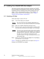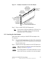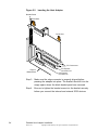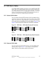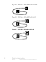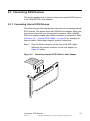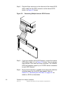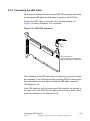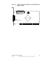
1
USER’S
GUIDE
Ultra320 SCSI
Host Adapters
April 2004
Version 2.2
®
DB15-000192-03
Electromagnetic Compatibility Notices
This device complies with Part 15 of the FCC Rules. Operation is subject to the following two conditions:
1.
2.
This device may not cause harmful interference, and
This device must accept any interference received, including interference that may cause undesired operation.
This equipment has been tested and found to comply with the limits for a Class B digital device, pursuant to part 15
of the FCC Rules. These limits are designed to provide reasonable protection against harmful interference in a
residential installation. This equipment generates, uses, and can radiate radio frequency energy and, if not installed
and used in accordance with the instructions, may cause harmful interference to radio communications. However,
there is no guarantee that interference will not occur in a particular installation. If this equipment does cause harmful
interference to radio or television reception, which can be determined by turning the equipment off and on, the user
is encouraged to try to correct the interference by one or more of the following measures:
•
•
•
•
Reorient or relocate the receiving antenna.
Increase the separation between the equipment and the receiver.
Connect the equipment into an outlet on a circuit different from that to which the receiver is connected.
Consult the dealer or an experienced radio/TV technician for help.
Shielded cables for SCSI connection external to the cabinet are used in the compliance testing of this Product.
LSI Logic is not responsible for any radio or television interference caused by unauthorized modification of this
equipment or the substitution or attachment of connecting cables and equipment other than those specified by
LSI Logic. The correction of interferences caused by such unauthorized modification, substitution, or attachment will
be the responsibility of the user.
The LSI Logic Ultra320 SCSI to PCI Host Adapters (LSI20320, LSI20320-R, LSI20320L-R, LSIU320, LSIU320-R,
LSI20320A, LSI20320A-R, LSI21320, LSI21320-R, LSI22320, LSI22320-R, LSI22320T, LSI22320E, LSI22320E-R)
are tested to comply with FCC standards for home or office use.
This Class B digital apparatus meets all requirements of the Canadian Interference-Causing Equipment Regulations.
Cet appareil numérique de la classe B respecte toutes les exigences du Règlement sur le matériel brouilleur du
Canada.
This is a Class B product based on the standard of the Voluntary Control Council for Interference from Information
Technology Equipment (VCCI). If this is used near a radio or television receiver in a domestic environment, it may
cause radio interference. Install and use the equipment according to the instruction manual.
LSI Logic Asia, Inc. Taiwan Branch
10/F, 156, Min Sheng E. Rd., Section 3,
Taipei, Taiwan, R.O.C.
Tel: 886.2.2718.7828
FAX: 886.2.2718.8869
LSI Logic Corporation
North American Headquarters
Milpitas, CA
Tel: 408.433.8000
ii
Version 2.2
Copyright © 2002–2004 by LSI Logic Corporation. All rights reserved.
This document contains proprietary information of LSI Logic Corporation. The
information contained herein is not to be used by or disclosed to third parties
without the express written permission of an officer of LSI Logic Corporation.
LSI Logic products are not intended for use in life-support appliances, devices,
or systems. Use of any LSI Logic product in such applications without written
consent of the appropriate LSI Logic officer is prohibited.
Document DB15-000192-03, Version 2.2 (April 2004)
This document describes the LSI Logic Corporation Ultra320 SCSI Host
Adapters and will remain the official reference source for all revisions/releases of
this product until rescinded by an update.
The PCI/PCI-X/PCI Express interfaces are compatible with the PCI Local Bus
Specification, Revision 2.2, PCI-X Addendum to the PCI Local Bus Specification,
Revision 1.0a, and PCI Express Bridge Specification, Revision 1.0. The SCSI
interface is compatible with the ANSI draft standard X3T10.11/1142.
LSI Logic Corporation reserves the right to make changes to any products herein
at any time without notice. LSI Logic does not assume any responsibility or
liability arising out of the application or use of any product described herein,
except as expressly agreed to in writing by LSI Logic; nor does the purchase or
use of a product from LSI Logic convey a license under any patent rights,
copyrights, trademark rights, or any other of the intellectual property rights of
LSI Logic or third parties.
Copyright © 2002–2004 by LSI Logic Corporation. All rights reserved.
TRADEMARK ACKNOWLEDGMENT
LSI Logic, the LSI Logic logo design, Fusion-MPT, Integrated Mirroring,
Integrated RAID, Integrated Striping, and SureLINK are trademarks or registered
trademarks of LSI Logic Corporation. Windows and Windows NT are registered
trademarks of Microsoft Corporation. All other brand and product names may be
trademarks of their respective companies.
SR
To receive product literature, visit us at http://www.lsilogic.com.
For a current list of our distributors, sales offices, and design resource
centers, view our web page located at
http://www.lsilogic.com/contacts/index.html
iii
Version 2.2
Copyright © 2002–2004 by LSI Logic Corporation. All rights reserved.
iv
Version 2.2
Copyright © 2002–2004 by LSI Logic Corporation. All rights reserved.
Preface
This document is the user’s guide for all LSI Logic Ultra320 SCSI Host
Adapters. It contains a functional description of the Ultra320 SCSI host
adapters as well as physical and electrical specifications. It also contains
instructions for installing the host adapters and for connecting SCSI
devices to them.
Audience
This document assumes that you have some familiarity with SCSI
protocol and related support devices. This document benefits people
installing and using the various Ultra320 SCSI host adapters.
Organization
This document has the following chapters and appendix:
•
Chapter 1, Quick Installation Procedures, provides quick instructions
for installing your Ultra320 SCSI host adapter and Windows
device drivers.
•
Chapter 2, Detailed Host Adapter Installation, provides detailed
instructions for installing your Ultra320 SCSI host adapter.
•
Chapter 3, Ultra320 SCSI Host Adapter Characteristics, illustrates
the various Ultra320 SCSI host adapters and provides PCI and SCSI
interface information.
•
Appendix A, Glossary of Terms, provides definitions of terms used
in this book.
Ultra320 SCSI Host Adapters User’s Guide
Version 2.2
Copyright © 2002–2004 by LSI Logic Corporation. All rights reserved.
v
Related Publications
LSI53C1020/1020A PCI to Ultra320 SCSI Controller Technical Manual,
Document No. DB14-000176-06
LSI53C1030 PCI to Dual Channel Ultra320 SCSI Multifunction Controller
Technical Manual, Document No. DB14-000156-05
Fusion-MPT™ Device Management User’s Guide, Document No.
DB15-000186-01
Integrated RAID User’s Guide, Document No. DB15-000292-00
Revision Record
Version
vi
Date
Remarks
1.0
9/2001
This release provides information about the LSI22320-R, LSI21320, and
LSI20320 Ultra320 SCSI to PCI Host Adapters.
2.0
5/2002
Final version.
2.1
7/2003
Corrected glossary entries for Ultra160 and Ultra320. Other minor editing also.
In Section 3.3.2, corrected storage temp range to −40 °C to 105 °C.
2.2
4/2004
Added the following host adapters: LSIU320, LSIU320-R, LSI20320A,
LSI20320A-R, LSI20320L-R, LSI22320T, LSI22320E and LSI22320E-R. Added
information about Integrated RAID (IR). Deleted the LSI20320H host adapter.
Preface
Version 2.2
Copyright © 2002–2004 by LSI Logic Corporation. All rights reserved.
Contents
Chapter 1
Chapter 2
Chapter 3
Quick Installation Procedures
1.1
General Description
1.2
Quick Host Adapter Installation
1.3
Quick Windows Driver Installation
Detailed Host Adapter Installation
2.1
Installing Your Ultra320 SCSI Host Adapter
2.1.1
Selecting a PCI Slot
2.1.2
Inserting the Host Adapter
2.2
SCSI Device Cables
2.2.1
Internal SCSI Cables
2.2.2
External SCSI Cable
2.3
Connecting SCSI Devices
2.3.1
Connecting Internal SCSI Devices
2.3.2
Connecting the LED Cable
2.3.3
Connecting External SCSI Devices
2.4
Terminating the SCSI Bus
2.5
Setting SCSI IDs
2.6
Completing the Installation
2.7
Setting Up Integrated RAID (IR) Solution
2.7.1
Integrated Mirroring (IM) Solution
2.7.2
Integrated Striping (IS) Solution
Ultra320 SCSI Host Adapter Characteristics
3.1
Ultra320 SCSI Host Adapters
3.1.1
LSI20320 Single Channel Host Adapters
3.1.2
LSIU320 and LSI20320A Single Channel
Host Adapters
Ultra320 SCSI Host Adapters User’s Guide
Version 2.2
Copyright © 2002–2004 by LSI Logic Corporation. All rights reserved.
1-1
1-2
1-4
2-2
2-2
2-3
2-5
2-5
2-5
2-7
2-7
2-9
2-10
2-12
2-13
2-14
2-15
2-15
2-16
3-1
3-2
3-4
vii
3.2
3.3
Appendix A
3.1.3
LSI21320 Dual Channel Host Adapters
3.1.4
LSI22320 Dual Channel Host Adapters
3.1.5
LSI22320E Dual Channel Host Adapters
Host Adapter Characteristics
Technical Specifications
3.3.1
Electrical Characteristics
3.3.2
Thermal and Atmospheric Characteristics
3.3.3
Safety Characteristics
Glossary of Terms
Customer Feedback
viii
Contents
Version 2.2
Copyright © 2002–2004 by LSI Logic Corporation. All rights reserved.
3-6
3-8
3-10
3-12
3-12
3-12
3-13
3-13
Figures
2.1
2.2
2.3
2.4
2.5
2.6
2.7
2.8
2.9
2.10
2.11
2.12
3.1
3.2
3.3
3.4
3.5
3.6
Hardware Connections for the Host Adapter
Inserting the Host Adapter
SCSI Cable – 68-Pin High Density with Terminator
SCSI Cable – 68-Pin High Density without Terminator
SCSI Cable – 68-Pin VHDCI to 68-Pin VHDCI
SCSI Cable – 68-Pin VHDCI to 68-Pin HD
SCSI Cable – 68-Pin HD to 68-Pin HD
Connecting Internal SCSI Cable to Host Adapter
Connecting Multiple Internal SCSI Devices
SCSI LED Connector
Connecting One External SCSI Device
Connecting Multiple External SCSI Devices
LSI20320, LSI20320-R, and LSI21320L-R Host
Adapter Drawing
LSIU320, LSIU320-R, LSI20320A, and LSI20320A-R
Host Adapter Drawing
LSI21320 and LSI21320-R Host Adapter Drawing
LSI22320 and LSI22320-R Host Adapter Drawing
LSI22320T Host Adapter Drawing
LSI22320E and LSI22320E-R Host Adapter Drawing
2-3
2-4
2-5
2-5
2-6
2-6
2-6
2-7
2-8
2-9
2-10
2-11
Ultra320 SCSI Controllers and Host Adapters
SCSI ID Record for Dual Channel Host Adapter
Host Adapter Installation Checklist
Ultra320 SCSI to PCI/PCI-X or PCI Express x4
Host Adapters
Host Adapter Characteristics
Maximum Power Requirements
1-1
2-13
2-14
3-3
3-5
3-7
3-9
3-9
3-11
Tables
1.1
2.1
2.2
3.1
3.2
3.3
3-1
3-12
3-13
ix
Version 2.2
Copyright © 2002–2004 by LSI Logic Corporation. All rights reserved.
x
Version 2.2
Copyright © 2002–2004 by LSI Logic Corporation. All rights reserved.
Chapter 1
Quick Installation
Procedures
This chapter contains general information about Ultra320 SCSI
controllers and host adapters. It provides quick host adapter installation
instructions and SCSI bus setup for experienced computer users. It also
provides quick installation instructions for Windows device drivers. This
chapter includes these topics:
•
Section 1.1, “General Description”
•
Section 1.2, “Quick Host Adapter Installation”
•
Section 1.3, “Quick Windows Driver Installation”
1.1 General Description
LSI Logic provides high-performance, cost-effective Ultra320 SCSI
controllers and host adapters. Table 1.1 shows the LSI Logic controllers
and their associated host adapters that support Ultra320 SCSI. For
specific information about the Ultra320 SCSI controllers, refer to the
Related Publications section on page vi in the Preface. Letters at the end
of an adapter name indicates a feature such as: A = low cost;
E = PCI Express; L = low profile; R = Integrated RAID™ solution; and
T = target mode.
Table 1.1
Ultra320 SCSI Controllers and Host Adapters
Controllers
Host Adapters
LSI53C1020
LSI20320, LSI20320-R, LSI20320L-R
LSI53C1020A
LSIU320, LSIU320-R, LSI20320A, LSI20320A-R
LSI22320E, LSI22320E-R
LSI53C1030
LSI21320, LSI21320-R, LSI22320, LSI22320-R
LSI53C1030T
LSI22320T
Ultra320 SCSI Host Adapters User’s Guide
Version 2.2
Copyright © 2002–2004 by LSI Logic Corporation. All rights reserved.
1-1
Installing any of these host adapters in your PCI/PCI-X/PCI Express
system allows you to connect up to 15 SCSI devices per channel over a
SCSI bus. The LSI20320L-R is designed with a bracket that is suitable
for low profile applications.
To achieve Ultra320 SCSI performance, you must connect only
Low Voltage Differential (LVD) devices to the host adapter. If you connect
single-ended (SE) devices and LVD devices, the entire bus drops to the
lower SE speed, limiting bus performance to Ultra SCSI.
The Ultra320 SCSI host adapters support all major operating systems
(OS), such as Windows (NT 4.0, 2000, 2003, and XP), Linux, NetWare,
UnixWare, SCO OpenServer 5.x, and Solaris SPARC. Other software
support includes SureLINK™ Domain Validation, which ensures
data integrity by intelligently testing the SCSI interconnect before
completing negotiation.
The Ultra320 SCSI host adapters utilize Fusion-MPT™ architecture for
all major operating systems, which allows for thinner drivers and better
performance. To obtain a device driver that supports your operating
system, contact the LSI Logic technical support team at 800-633-4545
or visit the LSI Logic web site at http://www.lsilogic.com.
1.2 Quick Host Adapter Installation
Use these quick installation steps if you have installed computer add-in
boards before and connected devices to them. For more detailed
instructions and guidance, refer to Section 2.1, “Installing Your Ultra320
SCSI Host Adapter,” on page 2-2.
To install an Ultra320 SCSI host adapter, follow these steps:
Step 1. Turn off and unplug the computer.
Warning:
Be sure to disconnect the computer’s power before you
remove the cover and install the Ultra320 SCSI host
adapter. Failure to do so may result in exposure to shock,
electrical hazards, and/or mechanical hazards.
Step 2. Open your computer cabinet by removing its cover.
1-2
Quick Installation Procedures
Version 2.2
Copyright © 2002–2004 by LSI Logic Corporation. All rights reserved.
Step 3. Be sure to touch a grounded metal surface to discharge static
electricity before handling the host adapter.
Step 4. Remove the host adapter from its packaging and examine it for
any damage.
Step 5. Locate an unused PCI/PCI-X/PCI Express slot.
Step 6. Insert your SCSI host adapter into the selected slot.
Step 7. Connect the internal and external SCSI devices to connectors
on one SCSI channel.
Step 8. Install SCSI bus terminators at the ends of the SCSI bus.
The SCSI bus must be properly terminated.
Step 9. Set the SCSI IDs for all devices and record them for future
reference.
Step 10. Make any configuration changes.
Step 11. Before replacing the cover on your computer, verify your
installation:
- Is the host adapter connection in the PCI/PCI-X/PCI Express
bus slot secure?
- Are the internal SCSI bus connections secure?
- Are the external SCSI bus connections secure?
- Is the SCSI bus terminated correctly?
- Have the SCSI IDs been set and recorded for each device?
Step 12. Replace the cabinet cover on your computer.
Step 13. Plug in all power cords and turn on power to all devices and
your computer.
Step 14. Wait for your computer to start up.
The host adapter installation is complete.
Quick Host Adapter Installation
Version 2.2
Copyright © 2002–2004 by LSI Logic Corporation. All rights reserved.
1-3
1.3 Quick Windows Driver Installation
To load the SYMMPI.SYS miniport driver during a new Windows NT,
Windows 2000, Windows XP, or Windows .NET system installation, you
can boot directly from the Microsoft installation CD-ROM. The Windows
drivers are not interchangeable; however, the instructions are very similar.
To install a new Windows operating system and its appropriate device
driver, follow these steps:
Step 1. Have the Microsoft Windows driver diskette available to insert
into drive A when prompted.
Step 2. Boot the computer from the Microsoft Windows CD-ROM.
Step 3. Press F6 when the words Setup is inspecting your
computer's hardware configuration appear, or when
Windows prompts you for nonsupported drivers.
Important:
You must press F6 for the new driver to be recognized.
Otherwise, the system does not recognize the devices
controlled by the driver during the Windows setup.
Step 4. Follow the instructions until a screen displaying the words
Setup could not determine the type of one or more mass
storage device… appear.
Step 5. Choose S to Specify Additional Devices.
Step 6. Follow the prompts and insert the Windows driver diskette
when prompted.
Step 7. Follow the Microsoft Windows installation procedure to
complete the installation. Microsoft provides documentation
with its installation CD-ROM.
Step 8. If you are installing Windows NT 4.0, also install the
Service Packs 5 or higher after Windows NT 4.0 has been
installed.
Note:
1-4
Refer to the Fusion-MPT™ Device Management User’s
Guide for detailed configuration and installation instructions
for all firmware and drivers.
Quick Installation Procedures
Version 2.2
Copyright © 2002–2004 by LSI Logic Corporation. All rights reserved.
Chapter 2
Detailed Host Adapter
Installation
This chapter provides detailed instructions on how to install the LSI Logic
Ultra320 SCSI host adapters and includes these topics:
•
Section 2.1, “Installing Your Ultra320 SCSI Host Adapter”
•
Section 2.2, “SCSI Device Cables”
•
Section 2.3, “Connecting SCSI Devices”
•
Section 2.4, “Terminating the SCSI Bus”
•
Section 2.5, “Setting SCSI IDs”
•
Section 2.6, “Completing the Installation”
•
Section 2.7, “Setting Up Integrated RAID (IR) Solution”
Ultra320 SCSI Host Adapters User’s Guide
Version 2.2
Copyright © 2002–2004 by LSI Logic Corporation. All rights reserved.
2-1
2.1 Installing Your Ultra320 SCSI Host Adapter
This section provides detailed instructions for installing your Ultra320
SCSI host adapter and connecting your SCSI devices to it. The following
illustrations show the LSI22320-R Dual Channel Ultra320 SCSI host
adapter. However, these illustrations apply to all host adapters. For
details on all the Ultra320 SCSI host adapters, refer to Chapter 3,
“Ultra320 SCSI Host Adapter Characteristics.”
2.1.1 Selecting a PCI Slot
Follow these steps to locate a PCI slot.
Step 1. Turn off and unplug your computer.
Warning:
Be sure to disconnect the computer’s power before you
remove the cover and install the Ultra320 SCSI host adapter.
Step 2. Open your computer cabinet by removing its cover.
Step 3. Be sure to touch a grounded metal surface to discharge static
electricity before removing the host adapter from its package.
Caution:
You must touch a grounded metal surface before handling
the host adapter because static charges on your body can
damage electronic components. Handle plug-in boards by
the edge; do not touch board components or gold
connector contacts. LSI Logic recommends that you use a
static ground strap.
Step 4. Remove your Ultra320 SCSI host adapter from its packaging
and verify that it is not damaged.
Figure 2.1 illustrates the LSI22320 series host adapter and Figure 2.2
illustrates the LSI22320E-R host adapter.
2-2
Detailed Host Adapter Installation
Version 2.2
Copyright © 2002–2004 by LSI Logic Corporation. All rights reserved.
Figure 2.1
Hardware Connections for the Host Adapter
Channel A
68-Pin Internal
High Density (HD)
SCSI Interface
J6 Connector
Channel B
68-Pin Internal
HD SCSI Interface
J4 Connector
Channel A & B
Busy LED
J5 Connector
Channel B
68-Pin External
Very High Density Cable
Interconnect (VHDCI)
SCSI J3 Connector
Channel A
68-Pin External
VHDCI SCSI
J2 Connector
J1 Card Connector
Universal Type Board Edge
PCI/PCI-X/PCI Express Bus to Mainboard
Step 5. Find an unused PCI/PCI-X/PCI Express slot.
Note:
You can insert a 64-bit host adapter into a 32-bit slot if no
64-bit slots are available. However, this limits the data
transmission rate to 32-bit transfers.
2.1.2 Inserting the Host Adapter
Follow these steps to install your Ultra320 SCSI host adapter in the
PC mainboard.
Step 1.
Remove the blank bracket panel on the back of the computer that
is aligned with the PCI/PCI-X/PCI Express slot you have selected.
Save the bracket screw.
Step 2. Carefully insert the edge connector into the PCI Express slot.
Caution:
Apply even pressure to both top corners of the board while
inserting it, as shown in Figure 2.2.
Caution:
Do not apply pressure to the center of the board, or to any
add-on cards that are connected to the host bus adapter.
Installing Your Ultra320 SCSI Host Adapter
Version 2.2
Copyright © 2002–2004 by LSI Logic Corporation. All rights reserved.
2-3
Figure 2.2
Inserting the Host Adapter
Bracket Screw
Press Here
Press Here
PCI Connectors
PCI Express
Connector x16
PCI Express
Connector x4
Edge of
Motherboard
Step 3. Make sure the edge connector is properly aligned before
pressing the adapter into place. The bracket should fit into the
empty space where the blank bracket panel was removed.
Step 4. Be sure to tighten the bracket screw into the bracket securely
before you connect the internal and external SCSI devices.
2-4
Detailed Host Adapter Installation
Version 2.2
Copyright © 2002–2004 by LSI Logic Corporation. All rights reserved.
2.2 SCSI Device Cables
For reliable Ultra320 operation, be sure to use an Ultra320-rated SCSI
device cable. The internal Ultra320 SCSI device cable also has built-in
low voltage differential (LVD) and single-ended termination. This built-in
feature is included because most LVD SCSI hard disk drives are not
made with on-board low voltage differential termination.
2.2.1 Internal SCSI Cables
You can connect all internal SCSI devices to the host adapter with an
unshielded, twisted pair, 68-pin ribbon cable. Some 68-pin internal SCSI
cables come with a low voltage differential and single-ended terminator
on one end, which must be farthest from the host adapter. Figure 2.3 and
Figure 2.4 show internal SCSI cables with and without a terminator.
Figure 2.3
SCSI Cable – 68-Pin High Density with Terminator
n
Terminator
Figure 2.4
SCSI Cable – 68-Pin High Density without Terminator
2.2.2 External SCSI Cable
You must connect all external SCSI devices to the host adapter with
shielded cables. Figures 2.5 to 2.7 are examples of external SCSI
cables. Select the correct 68-pin cable for your devices.
SCSI Device Cables
Version 2.2
Copyright © 2002–2004 by LSI Logic Corporation. All rights reserved.
2-5
Figure 2.5
SCSI Cable – 68-Pin VHDCI to 68-Pin VHDCI
Figure 2.6
SCSI Cable – 68-Pin VHDCI to 68-Pin HD
.
Figure 2.7
2-6
SCSI Cable – 68-Pin HD to 68-Pin HD
Detailed Host Adapter Installation
Version 2.2
Copyright © 2002–2004 by LSI Logic Corporation. All rights reserved.
2.3 Connecting SCSI Devices
This section explains how to connect internal and external SCSI devices
to the Ultra320 SCSI host adapters.
2.3.1 Connecting Internal SCSI Devices
This subsection provides step-by-step instructions for connecting internal
SCSI devices. The figures show the LSI22320 host adapter, which has
two internal connectors and two external connectors. Other Ultra320
SCSI host adapter models have different numbers of connectors. Refer
to Section 2.2.1, “Internal SCSI Cables,” on page 2-5 for examples of
internal cables. Follow these steps for making connections:
Step 1. Plug the 68-pin connector on the end of the SCSI ribbon
cable into the internal connector on the host adapter, as
Figure 2.8 shows.
Figure 2.8
Connecting Internal SCSI Cable to Host Adapter
Connecting SCSI Devices
Version 2.2
Copyright © 2002–2004 by LSI Logic Corporation. All rights reserved.
2-7
Step 2. Plug the 68-pin connector on the other end of the internal SCSI
ribbon cable into the SCSI connector on the internal SCSI
device, as Figure 2.9 shows.
Figure 2.9
Connecting Multiple Internal SCSI Devices
.
Step 3. If you have another internal SCSI device, connect the internal
SCSI ribbon cable to it, as Figure 2.9 shows. You can connect
other devices if the cable has more connectors. The Ultra320
SCSI host adapters support up to 15 SCSI devices connected
to each SCSI channel.
Step 4. Be sure that termination is enabled at the end of the cable that
is farthest away from the SCSI host adapter. Refer to
Section 2.4, “Terminating the SCSI Bus,” on page 2-12 for
details on SCSI bus termination.
2-8
Detailed Host Adapter Installation
Version 2.2
Copyright © 2002–2004 by LSI Logic Corporation. All rights reserved.
2.3.2 Connecting the LED Cable
Most computer cabinets have a front panel LED. When properly connected,
the front panel LED lights up when there is activity on the SCSI bus.
Connect the LED cable to connector J5 on the host adapter, as
Figure 2.10 shows. Connector J5 is not keyed.
Figure 2.10 SCSI LED Connector
LED
Cable
LED Connector J5
Left two pins are for Channel A
Right two pins are for Channel B
The orientation of the LED cable does not matter as long as all four pins
are connected. If the LED does not light up during SCSI bus activity from
this host adapter, you may have to rotate the LED cable connector
180 degrees on J5.
If the LED cable has only two wires, place the connector on one end or
the other of J5. If the LED does not light up when there is SCSI activity,
move the connector to the other half of J5.
Connecting SCSI Devices
Version 2.2
Copyright © 2002–2004 by LSI Logic Corporation. All rights reserved.
2-9
2.3.3 Connecting External SCSI Devices
This section provides step-by-step instructions for connecting external
SCSI devices. Refer to Section 2.2.2, “External SCSI Cable,” on page 2-5
for examples of external cables.
Step 1. Plug the 68-pin connector on one end of a shielded external
SCSI cable into the host adapter’s external SCSI connector.
This connector is exposed on the back panel of your computer.
Step 2. Plug the 68-pin connector on the other end of the shielded
external SCSI cable into the SCSI connector on the first
external SCSI device.
Figure 2.11 shows how to connect a single external SCSI device.
If you have the correct cable, it matches the external connector.
Figure 2.11 Connecting One External SCSI Device
Terminator
2-10
Detailed Host Adapter Installation
Version 2.2
Copyright © 2002–2004 by LSI Logic Corporation. All rights reserved.
Step 3. Connect any additional SCSI devices to one another with
shielded external SCSI cables. You need a separate SCSI
cable for each additional device.
Figure 2.12 shows how to connect multiple external SCSI
devices.
Figure 2.12 Connecting Multiple External SCSI Devices
Enable termination
on the device at the
end of the bus.
Disable
termination on all
devices not at the
end of the bus.
Host Adapter
Automatically
Terminated
Step 4. Be sure that termination is enabled only on the last external
SCSI device, as Figure 2.12 shows. Refer to Section 2.4,
“Terminating the SCSI Bus,” on page 2-12 for details on SCSI
bus termination.
Connecting SCSI Devices
Version 2.2
Copyright © 2002–2004 by LSI Logic Corporation. All rights reserved.
2-11
2.4 Terminating the SCSI Bus
The SCSI bus contains all the devices that you connect with SCSI cables.
When you connect the first and last physical SCSI devices on the ends
of the SCSI bus, you must have termination active. You must remove or
disable termination on all other SCSI devices on the same bus.
If you connect only internal SCSI devices on a bus, the host adapter
automatically terminates itself. If you connect only external SCSI devices
on a bus, the host adapter also terminates automatically. Automatic
termination occurs because the host adapter connection is at the end of
the SCSI bus. If you connect both internal and external SCSI devices on
a bus, the host adapter automatically disables its termination. This
occurs because the host adapter is in the middle of the SCSI bus.
Termination for host adapters with only one connector per channel is
always enabled for the channel.
2-12
Detailed Host Adapter Installation
Version 2.2
Copyright © 2002–2004 by LSI Logic Corporation. All rights reserved.
2.5 Setting SCSI IDs
SCSI IDs identify each SCSI device on the SCSI bus. Each SCSI ID on
a given bus must be unique. The IDs are 0–15 for a 16-bit bus. The
preset host adapter ID setting is 7, which gives the highest priority to the
host adapter.
Typically, you set the SCSI ID of the SCSI device with jumpers or with a
switch on the device. You must not duplicate SCSI IDs on a SCSI bus.
LSI Logic recommends that you record the SCSI IDs of all SCSI devices.
Table 2.1 provides a place to keep this record.
Table 2.1
SCSI ID
SCSI ID Record for Dual Channel Host Adapter
SCSI Device Channel A
SCSI Device Channel B
Ultra320 SCSI host adapter
Ultra320 SCSI host adapter
15
14
13
12
11
10
9
8
7
6
5
4
3
2
1
0
Setting SCSI IDs
Version 2.2
2-13
Copyright © 2002–2004 by LSI Logic Corporation. All rights reserved.
2.6 Completing the Installation
Before replacing the cover on your computer, complete the checklist as
shown in Table 2.2.
Table 2.2
Host Adapter Installation Checklist
Verify Installation Procedures
Done
Host adapter connection in PCI/PCI-X/PCI Express bus slot is
secure (level)
Internal SCSI bus connections are secure (pin-1 continuity)
External SCSI bus connections are secure
Proper SCSI bus termination established
Unique SCSI IDs set and recorded for each device
After you verify all items on the checklist, follow these steps:
Step 1. Replace the cabinet cover on your computer.
Step 2. Plug in all power cords, and turn on power to all devices and
your computer.
Step 3. Wait for your computer to boot up.
Note:
2-14
To change default configurations of the Ultra320 SCSI host
adapters, refer to the Fusion-MPT™ Device Management
System User’s Guide.
Detailed Host Adapter Installation
Version 2.2
Copyright © 2002–2004 by LSI Logic Corporation. All rights reserved.
2.7 Setting Up Integrated RAID (IR) Solution
The ‘‘R’’ at the end of a host adapter name indicates the board supports
the Integrated RAID solution. The Integrated RAID solution provides cost
benefits for the server or workstation market where the extra performance,
storage capacity, and/or redundancy of a RAID configuration are required.
The two components of the Integrated RAID solution are:
•
Integrated Mirroring™ (IM) solution, which provides features of
RAID 1 and RAID 1E
•
Integrated Striping™ (IS) solution, which provides features of RAID 0
By simplifying the IM and IS options and by providing firmware support
in its host adapters, LSI Logic can offer the Integrated RAID solution at
a lower cost than a dedicated processor based RAID implementation.
The Fusion-MPT Common Information Model (CIM) interface software
continuously monitors IM volumes and IS volumes, and reports status
and error conditions as they arise.
IM and IS are supported by different versions of the Fusion-MPT
firmware. Therefore, either IM or IS can be implemented on a system
with a Fusion-MPT based host adapter, but IM and IS cannot be used
concurrently on the same system.
The Fusion-MPT BIOS Configuration Utility (CU) configures the IM or IS
volume, which can use from two to six disk drives. The BIOS and drivers
support SCSI Domain Validation. Host-based CIM software monitors the
state of the physical disks and reports error conditions as they arise.
2.7.1 Integrated Mirroring (IM) Solution
As a result of the shift toward Network Attached Storage (NAS), ISPs
need a cost effective, fault-tolerant solution to protect the operating
systems on small form factor, high-density, rack-mountable servers. The
Integrated Mirroring (IM) solution provides data protection for the system
boot volume to safeguard critical information such as the OS on servers
and high performance workstations. This new Integrated Mirroring
solution gives customers a robust, high-performance, fault-tolerant
solution that is less expensive than a dedicated RAID controller.
Setting Up Integrated RAID (IR) Solution
Version 2.2
Copyright © 2002–2004 by LSI Logic Corporation. All rights reserved.
2-15
2.7.2 Integrated Striping (IS) Solution
The Integrated Striping (IS) solution is targeted at applications that
require the faster performance and increased storage capacity of
striping. The IS solution is a low-cost solution with many of the features
of a more expensive RAID striping solution. A single IS logical drive may
be configured as the boot disk or as a data disk.
To set up the Integrated RAID (IM and IS) features, refer to the Integrated
RAID User’s Guide.
2-16
Detailed Host Adapter Installation
Version 2.2
Copyright © 2002–2004 by LSI Logic Corporation. All rights reserved.
Chapter 3
Ultra320 SCSI
Host Adapter
Characteristics
This chapter describes the LSI Logic Ultra320 SCSI host adapters. This
chapter includes these topics:
•
Section 3.1, “Ultra320 SCSI Host Adapters”
•
Section 3.2, “Host Adapter Characteristics”
•
Section 3.3, “Technical Specifications”
3.1 Ultra320 SCSI Host Adapters
PCI, PCI-X and PCI Express are high-speed standard local buses for
interfacing a number of I/O components to the processor and memory
subsystems in a high-end PC. Table 3.1 lists the Ultra320 SCSI to
PCI/PCI-X or PCI Express x4 host adapters.
Table 3.1
Adapter
Ultra320 SCSI to PCI/PCI-X or PCI Express x4 Host Adapters
SCSI Channel
IR Support
Bracket
Board Dimensions
LSI20320
Single Channel
–
Standard
6.6 x 2.53 inches, 167.6 x 64.3 mm
LSI20320-R
Single Channel
IR support
Standard
6.6 x 2.53 inches, 167.6 x 64.3 mm
LSI20320L-R
Single Channel
IR support
Low Profile
6.6 x 2.53 inches, 167.6 x 64.3 mm
LSI20320A
Single Channel
–
Standard
6.6 x 3.27 inches, 167.6 x 83.1 mm
LSI20320A-R
Single Channel
IR support
Standard
6.6 x 3.27 inches, 167.6 x 83.1 mm
LSIU320
Single Channel
–
Standard
6.6 x 3.27 inches, 167.6 x 83.1 mm
LSIU320-R
Single Channel
IR support
Standard
6.6 x 3.27 inches, 167.6 x 83.1 mm
LSI21320
Dual Channel
–
Standard
6.6 x 3.27 inches, 167.6 x 83.1 mm
LSI21320-R
Dual Channel
IR support
Standard
6.6 x 3.27 inches, 167.6 x 83.1 mm
Ultra320 SCSI Host Adapters User’s Guide
Version 2.2
Copyright © 2002–2004 by LSI Logic Corporation. All rights reserved.
3-1
Table 3.1
Adapter
Ultra320 SCSI to PCI/PCI-X or PCI Express x4 Host Adapters (Cont.)
SCSI Channel
IR Support
Bracket
Board Dimensions
LSI22320
Dual Channel
–
Standard
6.6 x 4.0 inches, 167.6 x 101.6 mm
LSI22320-R
Dual Channel
IR support
Standard
6.6 x 4.0 inches, 167.6 x 101.6 mm
LSI22320T
Dual Channel
–
Standard
6.6 x 4.0 inches, 167.6 x 101.6 mm
LSI22320E
Dual Channel
–
Standard
7.75 x 4.376 inches, 196.9 x 106.7 mm
LSI22320E-R
Dual Channel
IR support
Standard
7.75 x 4.376 inches, 196.9 x 106.7 mm
The component height on the top and bottom of the Ultra320 SCSI
host adapters follows the PCI Local Bus Specification, Revision 2.2,
PCI-X Addendum to the PCI Local Bus Specification, Revision 1.0a, and
PCI Express to PCI/PCI-X Bridge Specification, Revision 1.0. The
Ultra320 SCSI host adapters are used in PCI/PCI-X and PCI Express
computer systems with PCI standard and PCI low profile bracket types.
3.1.1 LSI20320 Single Channel Host Adapters
The LSI20320 series of host adapters are single channel Ultra320 SCSI
host adapters that provide one Ultra320 SCSI channel. The SCSI
Channel A interface is made through connectors J1 and J3.
Features of the LSI20320 series of host adapters are:
•
single Ultra320 SCSI channel
•
two SCSI connectors
–
one external 68-pin very high density cable interconnect (VHDCI)
connection
–
one internal 68-pin high density (HD) connector
•
PCI low profile bracket (LSI20320L-R only)
•
LVD/SE termination
•
Integrated RAID (IR) solution applies to the ‘‘R’’ cards only
•
Fusion-MPT architecture
Details of the LSI20320 series of host adapters are:
3-2
•
J5: PCI and PCI-X, 64-bit, universal type board edge connector
•
J1: 68-pin VHDCI shielded right-angle external connector
Ultra320 SCSI Host Adapter Characteristics
Version 2.2
Copyright © 2002–2004 by LSI Logic Corporation. All rights reserved.
•
J3: 68-pin HD right-angle internal connector
•
HDR2: 4-pin low density unshrouded right-angle LED connector
•
Subsystem Vendor ID and Subsystem IDs are:
Host Adapter
Chip
Subsystem Vendor ID
Subsystem ID
LSI20320
1020
0x1000
50F0
LSI20320-R
1020
0x1000
7100
LSI20320L-R
1020
0x1000
1060
During system initialization, the system loads the ID numbers into the
Subsystem Vendor ID and Subsystem ID registers of the embedded
SCSI controller.
Figure 3.1 illustrates the LSI20320 series of host adapters. The
LSI20320L-R adapter uses a PCI low profile bracket.
Figure 3.1
LSI20320, LSI20320-R, and LSI21320L-R Host Adapter
Drawing
HDR2 Connector for
Channel A
J3
Channel A
Internal SCSI Connector
LSI53C1020
J1
Channel A
Ultra320 SCSI LVD/SE
J5 – PCI and PCI-X 64-Bit Edge Connector
Ultra320 SCSI Host Adapters
Version 2.2
Copyright © 2002–2004 by LSI Logic Corporation. All rights reserved.
3-3
3.1.2 LSIU320 and LSI20320A Single Channel Host Adapters
The LSIU320 and LSI20320A series of host adapters are single channel
Ultra320 SCSI host adapters that provide one Ultra320 SCSI channel.
The SCSI Channel A interface for is made through connectors J2 and J3.
Features of the LSIU320 and LSI20320A series of host adapters are:
•
single Ultra320 SCSI channel
•
two SCSI connectors
–
one external 68-pin HD connector
–
one internal 68-pin HD connector
•
LVD/SE termination
•
Integrated RAID (IR) solution applies to the ‘‘R’’ cards only
•
Fusion-MPT architecture
Details of the LSIU320 and LSI20320A series of host adapters are:
•
J1: PCI and PCI-X, 64-bit, universal type board edge connector
•
J2: 68-pin HD right-angle internal connector
•
J3: 68-pin HD right-angle internal connector
•
J4: 4-pin low density unshrouded right-angle LED connector
•
Subsystem Vendor ID and Subsystem IDs are:
Host Adapter
Chip
Subsystem Vendor ID
Subsystem ID
LSIU320
1020A
0x1000
5100
LSIU320-R
1020A
0x1000
5100
LSI20320A
1020A
0x1000
5100
LSI20320A-R
1020A
0x1000
5100
During system initialization, the system loads the ID numbers into the
Subsystem Vendor ID and Subsystem ID registers of the embedded
SCSI controller.
Figure 3.2 illustrates the LSIU320 and LSI20320A series of host
adapters.
3-4
Ultra320 SCSI Host Adapter Characteristics
Version 2.2
Copyright © 2002–2004 by LSI Logic Corporation. All rights reserved.
Figure 3.2
LSIU320, LSIU320-R, LSI20320A, and LSI20320A-R Host
Adapter Drawing
J3
Channel A
Ultra320 SCSI LVD/SE
J4 LED Connector
LSI53C1020A
J2
Channel A
Ultra320 SCSI LVD/SE
J1 – PCI and PCI-X
Ultra320 SCSI Host Adapters
Version 2.2
Copyright © 2002–2004 by LSI Logic Corporation. All rights reserved.
3-5
3.1.3 LSI21320 Dual Channel Host Adapters
The LSI21320 series of host adapters are dual channel Ultra320 SCSI host
adapters that provide two Ultra320 SCSI channels. The SCSI Channel A
interface is made through connectors J2 and J4. The SCSI Channel B
interface is made through connector J3. See Figure 3.3 for details.
Features of the LSI21320 series of host adapters are:
•
two independent Ultra320 SCSI channels
•
three SCSI connectors:
–
one external 68-pin HD connector
–
two internal 68-pin HD connectors
•
LVD/SE termination
•
Integrated RAID (IR) solution applies to the ‘‘R’’ cards only
•
Fusion-MPT architecture
Details of the LSI21320 series of host adapters are:
•
J1: PCI and PCI-X, 64-bit, universal type board edge connector
•
J2: 68-pin HD cable right-angle external connector
•
J3 and J4: 68-pin HD right-angle internal connectors
•
J6: 4-pin low density unshrouded right-angle LED connector
•
Subsystem Vendor ID and Subsystem IDs are:
Host Adapter
Chip
Subsystem Vendor ID
Subsystem ID
LSI21320
1030
0x1000
10D0
LSI21320-R
1030
0x1000
30E0
During system initialization, the system loads the ID numbers into the
Subsystem Vendor ID and Subsystem ID registers of the embedded
SCSI controller.
Figure 3.3 illustrates the LSI21320 series of host adapter board.
3-6
Ultra320 SCSI Host Adapter Characteristics
Version 2.2
Copyright © 2002–2004 by LSI Logic Corporation. All rights reserved.
Figure 3.3
LSI21320 and LSI21320-R Host Adapter Drawing
J4
Channel A
Ultra320 SCSI LVD/SE
J3
Channel B
Ultra320 SCSI LVD/SE
J6 for
Channels
A and B
LSI53C1030
J2
Channel A
Ultra320 SCSI LVD/SE
J1 – PCI and PCI-X
Ultra320 SCSI Host Adapters
Version 2.2
Copyright © 2002–2004 by LSI Logic Corporation. All rights reserved.
3-7
3.1.4 LSI22320 Dual Channel Host Adapters
The LSI22320 series of host adapters are dual channel Ultra320 SCSI
host adapters that provide two Ultra320 SCSI channels. The SCSI
Channel A interface is made through connectors J2 and J6. The SCSI
Channel B interface is made through connectors J3 and J4. See
Figure 3.4 and Figure 3.5 for details.
Features of the LSI22320 series of host adapters are:
•
two independent Ultra320 SCSI channels
•
four SCSI connectors:
–
two external 68-pin VHDCI connectors
–
two internal 68-pin HD connectors
•
LVD/SE termination
•
Integrated RAID (IR) solution applies to the ‘‘R’’ cards only
•
Fusion-MPT architecture
Details of the LSI22320 series of host adapters are:
•
J1: PCI and PCI-X, 64-bit, universal type board edge connector
•
J2 and J3: 68-pin VHDCI right-angle external connectors
•
J4 and J6: 68-pin HD right-angle internal connectors
•
J5: 4-pin low density unshrouded right-angle LED connector
•
Subsystem Vendor ID and Subsystem IDs are:
Host Adapter
Chip
Subsystem Vendor ID
Subsystem ID
LSI22320
1030
0x1000
1010
LSI22320-R
1030
0x1000
30B0
LSI22320T
1030T
0x1000
1110
During system initialization, the system loads the ID numbers into the
Subsystem Vendor ID and Subsystem ID registers of the embedded
SCSI controller.
Figure 3.4 illustrates the LSI22320 series of host adapter, and Figure 3.5
illustrates the LSI22320T host adapter.
3-8
Ultra320 SCSI Host Adapter Characteristics
Version 2.2
Copyright © 2002–2004 by LSI Logic Corporation. All rights reserved.
Figure 3.4
LSI22320 and LSI22320-R Host Adapter Drawing
J5
J4
Channel B
Ultra320 SCSI LVD/SE
J3
Channel B
Ultra320 SCSI LVD/SE
J6
Channel A
Ultra320 SCSI LVD/SE
LSI53C1030
J2
Channel A
Ultra320 SCSI LVD/SE
Figure 3.5
J1 – PCI and PCI-X
LSI22320T Host Adapter Drawing
J4
Channel B
Ultra320 SCSI LVD/SE
J3
Channel B
Ultra320 SCSI LVD/SE
J6
Channel A
Ultra320 SCSI LVD/SE
J5
LSI53C1030T
J2
Channel A
Ultra320 SCSI LVD/SE
J1 – PCI and PCI-X
Ultra320 SCSI Host Adapters
Version 2.2
Copyright © 2002–2004 by LSI Logic Corporation. All rights reserved.
3-9
3.1.5 LSI22320E Dual Channel Host Adapters
The LSI22320E series of host adapters are dual channel Ultra320 SCSI
host adapters that provide two Ultra320 SCSI channels. The SCSI
Channel A interface is made through connector J2. The SCSI Channel B
interface is made through connectors J3 and J5. See Figure 3.6 for details.
Features of the LSI22320E and LSI22320E-R host adapters are:
•
two independent Ultra320 SCSI channels
•
three SCSI connectors:
–
two external 68-pin VHDCI connectors
–
one internal 68-pin HD connectors
•
LVD/SE termination
•
Integrated RAID (IR) solution applies to the ‘‘R’’ cards and the
B Channel only
•
Fusion-MPT architecture
Details of the LSI22320 series of host adapters are:
•
J1: PCI-Express x4 lanes, serial board edge connector
•
J2 and J3: 68-pin VHDCI right-angle external connectors
•
J5: 68-pin HD right-angle internal connectors
•
HDR2: 4-pin low density unshrouded right-angle LED connector
•
Subsystem Vendor ID and Subsystem IDs are:
Host Adapter
Chip
Subsystem Vendor ID
Subsystem ID
LSI22320E
1020A
0x1000
1050
LSI22320E-R
1020A
0x1000
1050
During system initialization, the system loads the ID numbers into the
Subsystem Vendor ID and Subsystem ID registers of the embedded
SCSI controller.
Figure 3.6 illustrates the LSI22320E and the LSI22320E-R host adapter.
3-10
Ultra320 SCSI Host Adapter Characteristics
Version 2.2
Copyright © 2002–2004 by LSI Logic Corporation. All rights reserved.
Figure 3.6
LSI22320E and LSI22320E-R Host Adapter Drawing
HDR2
J5
Channel B
Ultra320 SCSI LVD/SE
J3
Channel B
Ultra320 SCSI LVD/SE
LSI53C1020A
LSI53C1020A
J2
Channel A
Ultra320 SCSI LVD/SE
J1 – PCI-Express
PCI Express
Bridge
Ultra320 SCSI Host Adapters
Version 2.2
Copyright © 2002–2004 by LSI Logic Corporation. All rights reserved.
3-11
3.2 Host Adapter Characteristics
Table 3.2 shows the general characteristics for all Ultra320 SCSI
host adapters.
Table 3.2
Host Adapter Characteristics
Flash Serial
LVD/SE
ROM1 EEPROM2 Signaling
Ultra320 SCSI
Data Transfers
SCSI
Features
SCSI
Termination
Yes
Up to 320 Mbytes/s as well as
Fast, Ultra, Ultra2, and
Ultra160 speeds; Synchronous
offsets up to 62.
Plug and Play
Scatter/Gather
Activity LED
TERMPWR with
autoresetting
circuit breaker
Yes
16-bit SE
or LVD
interfaces
1. For boot code and firmware.
2. For BIOS configuration storage.
Each Ultra320 SCSI host adapter offers SureLINK Domain Validation
technology to ensure data integrity by intelligently validating the
compatibility of the SCSI domain. These adapters also utilize Fusion-MPT
architecture that allows for thinner drivers and better performance.
3.3 Technical Specifications
The design and implementation of the Ultra320 SCSI host adapters
minimize electromagnetic emissions, susceptibility to radio frequency
energy, and the effects of electrostatic discharge. The adapter carries the
CE mark, C-Tick mark, FCC Self-Certification logo, Canadian
Compliance Statement, Korean MIC, Taiwan BSMI, Japan VCCI, and
meets the requirements of CISPR Class B.
3.3.1 Electrical Characteristics
Table 3.3 lists the maximum power requirements for standard
Ultra320 SCSI host adapters, including SCSI TERMPWR, under
normal operation.
3-12
Ultra320 SCSI Host Adapter Characteristics
Version 2.2
Copyright © 2002–2004 by LSI Logic Corporation. All rights reserved.
Table 3.3
Host
Adapter
LSI20320
LSI20320-R
LSI20320L-R
LSIU320
LSIU320-R
LSI20320A
LSI20320A-R
LSI21320
LSI21320-R
LSI22320
LSI22320-R
LSI22320T
LSI22320E
LSI22320E-R
Maximum Power Requirements
PCI/PCI-X PCI/PCI-X
+5.0 V
+3.3 V
PCI Express
+12 V
PCI PRSNT1#/
PRSNT2# Power
Temperature
Range
1.5 A
2.0 A
–
15 W
0 ˚C to 55 ˚C
1.5 A
2.0 A
–
7.5 W
0 ˚C to 55 ˚C
1.5 A
2.5 A
–
15 W
0 ˚C to 55 ˚C
2.5 A
0.0 A
–
15 W
0 ˚C to 55 ˚C
–
–
2.1 A
N/A
0 ˚C to 55 ˚C
3.3.2 Thermal and Atmospheric Characteristics
The thermal and atmospheric characteristics for all Ultra320 SCSI host
adapters are:
•
temperature range: 0 °C to 55 °C (dry bulb)
•
relative humidity range: 5% to 90% noncondensing
•
maximum dew point temperature: 32 °C
•
airflow must be sufficient to keep the LSI53C1020 and LSI53C1030
heat sink temperature below 80 °C
•
host adapters using the LSI53C1020A do not require a heat sink
The following parameters define the storage and transit environment for
the Ultra320 SCSI host adapters:
•
temperature range: −40 °C to 105 °C (dry bulb)
•
relative humidity range: 5% to 90% noncondensing
3.3.3 Safety Characteristics
All Ultra320 SCSI host adapters meet or exceed the requirements of UL
flammability rating 94 V0. Each bare board is also marked with the
supplier’s name or trademark, type, and UL flammability rating. Because
these boards are installed in a PCI bus slot, all voltages are below the
SELV 42.4 V limit.
Technical Specifications
Version 2.2
Copyright © 2002–2004 by LSI Logic Corporation. All rights reserved.
3-13
3-14
Ultra320 SCSI Host Adapter Characteristics
Version 2.2
Copyright © 2002–2004 by LSI Logic Corporation. All rights reserved.
Appendix A
Glossary of Terms
Active
Termination
The electrical connection required at each end of the SCSI bus,
composed of active voltage regulation and a set of termination resistors.
Ultra SCSI, Ultra2 SCSI, Ultra160 SCSI, and Ultra320 SCSI require
active termination.
BIOS
Basic Input/Output System. Software that provides basic read/write
capability. Usually kept as firmware (ROM-based). The system BIOS on
the mainboard of a computer boots and controls the system. The SCSI
BIOS on the host adapter acts as an extension of the system BIOS.
Configuration
Refers to the way a computer is set up; the combined hardware
components (computer, monitor, keyboard, and peripheral devices) that
make up a computer system; or the software settings that allow the
hardware components to communicate with each other.
Device Driver
A program that allows a microprocessor (through the operating system)
to direct the operation of a peripheral device, such as a disk drive.
Domain
Validation
A software procedure in which a host queries a device to determine its
ability to communicate at the negotiated data rate.
EEPROM
Electronically Erasable Programmable Read Only Memory. A memory
chip that typically stores configuration information.
External SCSI
Device
A SCSI device installed outside the computer cabinet. These devices are
connected together using specific types of shielded cables.
Fusion-MPT
Architecture
Fusion-MPT (Message Passing Technology) architecture consists of
several main elements: Fusion-MPT firmware, the Fibre Channel and
SCSI hardware, and the operating system level drivers that support these
architectures. Fusion-MPT architecture offers a single binary, operating
system driver that supports both Fibre Channel and SCSI devices.
Ultra320 SCSI Host Adapters User’s Guide
Version 2.2
Copyright © 2002–2004 by LSI Logic Corporation. All rights reserved.
A-1
Host
The computer system in which a SCSI host adapter is installed. It uses
the SCSI host adapter to transfer information to and from devices
attached to the SCSI bus.
Host Adapter
A circuit board or integrated circuit that provides a device connection to
the host.
Integrated RAID
(IR)
The LSI Logic Integrated RAID solution provides either the
Integrated Mirroring (IM) solution, which provides features of RAID 1 and
RAID 1E, or the Integrated Striping (IS) solution, which provides features
of RAID 0.
Integrated
Mirroring (IM)
The LSI Logic Integrated Mirroring (IM) solution provides features of
RAID 1 and RAID 1E. The IM feature provides data protection for the
system boot volume to safeguard critical information such as the
operating system on servers and high performance workstations. The IM
feature gives customers a robust, high-performance, fault-tolerant
solution that is less expensive than a dedicated RAID controller.
Integrated
Striping (IS)
The LSI Logic Integrated Striping (IS) solution provides features of RAID
0. The IS feature is a low-cost solution with many of the features of a
more expensive RAID striping solution. A single IS logical drive may be
configured as the boot disk or as a data disk.
Internal SCSI
Device
A SCSI device installed inside the computer cabinet. These devices are
connected to one another with an unshielded ribbon cable.
PCI and PCI-X
Peripheral Component Interconnect. A high performance local bus
specification that allows connection of devices directly to computer
memory. The PCI Local Bus allows transparent upgrades from a 32-bit
data path at 33 MHz to a 64-bit data path at 33 MHz; from a 32-bit data
path at 66 MHz to a 64-bit data path at 66 MHz; and from a 32-bit data
path at 133 MHz to a 64-bit data path at 133 MHz (1064 Mbytes/s peak).
PCI Express
PCI Express is the third generation high performance I/O bus that
interconnects peripheral devices. PCI Express replaces parallel PCI bus
with a highly scalable, fully serial interface. PCI Express takes advantage
of recent advances in point-to-point interconnects, switchbased technology,
and packetized protocol to deliver new levels of performance and features.
Peripheral
Device
A piece of hardware (such as a disk drive, printer, or CD-ROM) used with
a computer and under the computer’s control. SCSI peripheral devices
are controlled through a SCSI host adapter.
A-2
Glossary of Terms
Version 2.2
Copyright © 2002–2004 by LSI Logic Corporation. All rights reserved.
RAID
Redundant Array of Independent Disks. An array of multiple independent
hard disk drives that yields better performance than a Single Large
Expensive Disk (SLED). A RAID disk subsystem improves I/O
performance on a server using only a single drive. The RAID array
appears to the host server as a single storage unit. I/O is expedited
because several disks can be accessed simultaneously.
RAID 0
Provides block “striping” across multiple drives, yielding higher
performance than is possible with individual drives. This level does not
provide any redundancy.
RAID 1
Drives are paired and mirrored. All data is 100 percent duplicated on a
drive of equivalent size.
SCSI Bus
A host adapter and one or more SCSI devices connected by cables in a
linear configuration. The host adapter may exist anywhere on the bus,
allowing connection of both internal and external SCSI devices. A system
may have more than one SCSI bus by using a multichannel host adapter
or by using multiple host adapters.
SCSI Device
Any device that conforms to the SCSI standard and is attached to the
SCSI bus by a SCSI cable. This includes SCSI host adapters, SCSI disk
drives, SCSI CD-ROM drives, and so on.
SCSI ID
An identifier that addresses specific devices on the SCSI bus and
determines device selection when multiple devices contend for ownership
of the SCSI bus. Wide SCSI buses support SCSI IDs 0–15, and narrow
SCSI buses support SCSI IDs 0–7. A device gains ownership of the bus
according to the priority of its SCSI ID. The order of priority, from highest
to lowest, is: 7, 6, 5, 4, 3, 2, 1, 0, 15, 14, 13, 12, 11, 10, 9, 8. The host
adapter is usually set to the highest priority SCSI ID, which is SCSI ID 7.
Single-Ended
SCSI
A hardware specification for connecting SCSI devices. It references each
SCSI signal to a common ground. In contrast, differential SCSI uses a
separate ground for each signal.
SureLINK
The domain validation method developed and used by LSI Logic.
SureLINK Domain Validation provides three levels of integrity checking:
Basic (level 1), Enhanced (level 2), and Margined (level 3).
Ultra SCSI
A standard for SCSI data transfers. It allows a transfer rate of up to
20 Mbytes/s over an 8-bit SCSI bus and up to 40 Mbytes/s over a 16-bit
SCSI bus.
Glossary of Terms
Version 2.2
A-3
Copyright © 2002–2004 by LSI Logic Corporation. All rights reserved.
Ultra2 SCSI
A standard for SCSI data transfers. It allows a transfer rate of up to
40 Mbytes/s over an 8-bit SCSI bus, and up to 80 Mbytes/s over a 16-bit
SCSI bus.
Ultra160 SCSI
A standard for SCSI data transfers. It allows a transfer rate of up to
160 Mbytes/s over a 16-bit SCSI bus.
Ultra320 SCSI
A standard for SCSI data transfers. It allows a transfer rate of up to
320 Mbytes/s over a 16-bit SCSI bus.
VHDCI
Very High Density Cable Interconnect. VHDCI cables connect external
SCSI devices to the host adapter.
A-4
Glossary of Terms
Version 2.2
Copyright © 2002–2004 by LSI Logic Corporation. All rights reserved.
Customer Feedback
We would appreciate your feedback on this document. Please copy the
following page, add your comments, and fax it to us at the number
shown.
If appropriate, please also fax copies of any marked-up pages from this
document.
Important:
Please include your name, phone number, fax number, and
company address so that we may contact you directly for
clarification or additional information.
Thank you for your help in improving the quality of our documents.
Ultra320 SCSI Host Adapters User’s Guide
Version 2.2
Copyright © 2002–2004 by LSI Logic Corporation. All rights reserved.
Reader’s Comments
Fax your comments to:
LSI Logic Corporation
Technical Publications
M/S AF-198
Fax: 408.433.4333
Please tell us how you rate this document: Ultra320 SCSI Host Adapters
User’s Guide. Place a check mark in the appropriate blank for each
category.
Excellent Good Average
Completeness of information
Clarity of information
Ease of finding information
Technical content
Usefulness of examples and
illustrations
Overall manual
Fair
Poor
____
____
____
____
____
____
____
____
____
____
____
____
____
____
____
____
____
____
____
____
____
____
____
____
____
____
____
____
____
____
What could we do to improve this document?
If you found errors in this document, please specify the error and page
number. If appropriate, please fax a marked-up copy of the page(s).
Please complete the information below so that we may contact you
directly for clarification or additional information.
Name
Telephone
Title
Department
Company Name
Street
City, State, Zip
Date
Fax
Mail Stop
Customer Feedback
Version 2.2
Copyright © 2002–2004 by LSI Logic Corporation. All rights reserved.
You can find a current list of our U.S. distributors, international distributors, and sales
offices and design resource centers on our web site at
http://www.lsilogic.com/contacts/index.html