1
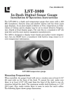
X-28, X-38,
and
X-48
INST
ALLA
TION AND OPERA
TION
INSTALLA
ALLATION
OPERATION
INSTR
UCTIONS
INSTRUCTIONS
TABLE OF CONTENTS
INTRODUCTION .............................................................................................. 1
SPECIFICATIONS ........................................................................................... 1
INSTALLATION -Transducer ........................................................................... 2
POWER CONNECTIONS ............................................................................... 11
BRACKET INSTALLATION ............................................................................ 12
SPEED/TEMP SENSORS .............................................................................. 13
KEYBOARD BASICS ...................................................................................... 16
DISPLAY ......................................................................................................... 16
OPERATION ................................................................................................... 17
MENUS ........................................................................................................... 17
AUTOMATIC ................................................................................................... 17
RANGE ........................................................................................................... 17
ZOOM ............................................................................................................. 18
UPPER/LOWER LIMITS ................................................................................. 20
SENSITIVITY .................................................................................................. 21
GRAYLINE® ............................................................................................................................................................................. 21
FISH ID ........................................................................................................... 22
FISH TRACK™ ............................................................................................... 23
TARGET TRACK ............................................................................................ 23
CHART SPEED .............................................................................................. 24
DISPLAY MODE ............................................................................................. 25
TEMPERATURE PROBE SELECT ................................................................ 28
ALARMS ......................................................................................................... 29
BACK LIGHT ................................................................................................... 30
FEET/METER ................................................................................................. 30
DISPLAY CONTRAST .................................................................................... 30
ASP (Advanced Signal Processing) ............................................................... 31
SIMULATOR ................................................................................................... 31
TROUBLESHOOTING .................................................................................... 32
WARRANTY ................................................................................................... 37
UPS RETURN SERVICE - U.S.A. ONLY ....................................................... 38
Copyright © 1998, Lowrance Electronics, Inc.
All rights reserved.
All features and specifications in this manual are subject to change
without notice.
All screens in this manual are simulated.
INTRODUCTION
Thank you for purchasing a Lowrance sonar. Your sonar unit is a high
quality unit designed for both professional and novice fishermen. All of our
sonars have an automatic feature that finds and displays the bottom, fish,
structure, and more! All you have to do is press the on key. However, if
you wish to fine tune the unit, all you have to do is press the menu key. This
series of sonar products has powerful features available through easy-touse menus.
To get started with your Lowrance unit, first read the installation section.
This is where it all begins. Improper installation can cause problems down
the road. After you’ve read the instructions, install the unit, then read the
rest of the manual. The more you know about your unit, the better it will
perform for you.
SPECIFICATIONS
Dimensions ......................
Input Voltage ....................
Current Drain ...................
...........................
Transmitter
Frequency ..........
Output Power .....
...........................
Display ...........................
...........................
5.9" W x 5.35" H x 3.4" D
10 - 15 vDC
350 ma (lights off)
500 ma (lights on)
192 kHz
600 watts (peak-to-peak) (typical)
75 watts (RMS)
128 pixels (H) x 65 pixels (W)
Supertwist Liquid Crystal Display
3.4"
5.35"
5.9"
NOTICE!
The storage temperature for your unit is from -4 degrees to +167 degrees
Fahrenheit (-20 degrees to +75 degrees Celcius). Extended storage in temperatures higher or lower than specified will damage the liquid crystal display in your
unit. This type of damage is not covered by the warranty. For more information,
contact the factory customer service department or your local service center.
1
Transducer Installation
Some of the models covered by this manual have a transom-mount
transducer included. The following are installation instructions for this
transducer.
The “kick-up” mounting bracket helps prevent damage if the transducer
strikes an object while the boat is moving. If the transducer does “kickup”, the bracket can easily be pushed back in place without tools.
Read this manual carefully before attempting the installation. Determine
which of the mounting positions is right for your boat. Use extreme care
if mounting the transducer inside the hull, since once it is epoxied into
position, the transducer usually cannot be removed. Remember, the
transducer location is the most critical part of a sonar installation.
Location - General
1. The transducer must be placed in a location that has a smooth flow of
water at all times. If the transducer is to be mounted inside the hull,
then the chosen location must be in the water at all times. If the
transducer is not placed in a smooth flow of water, interference will
show on the sonar’s display in the form of random lines or dots
whenever the boat is moving.
2. The transducer should be installed with it’s face pointing straight
down, if possible.
3. If the transducer is mounted on the transom, make certain it doesn’t
interfere with the trailer or hauling of the boat. Also, don’t mount it
closer than approximately one foot from the engine’s lower unit. This
will prevent cavitation interference with the propeller. Typically, the
transducer should be mounted as deep in the water as possible. This
increases the chance that it will be in the water in high speed and
reduces the possiblity of air bubble interference.
4. If possible, route the transducer cable away from other wiring on the
boat. Electrical noise from engine wiring, bilge pumps, and areators
can be displayed on the sonar’s screen. Use caution when routing
the transducer cable around these wires.
2
Shoot-thru-hull v.s. Transom Mounting
(X-28 and X-38 Only)
Typically, shoot-thru-hull installations give excellent high speed operation and good to excellent depth capability. There is no possibility of
damage from floating objects. It can't be knocked off when docking or
loading on the trailer.
However, the shoot-thru-hull installation does have its drawbacks. One,
some loss of sensitivity does occur, even on the best hulls. This varies
from hull to hull, even from different installations on the same hull. This
is caused by differences in hull layup and construction. Two, the angle
of the transducer cannot be adjusted for the best fish arches. This can
be a problem on some hulls that sit with the bow high when at rest or at
slow trolling speeds. Follow the procedure listed in the shoot-thru-hull
installation section in this manual to determine if you can satisfactorily
shoot through the hull.
Transducer Assembly and Mounting - All Units
The best way to install this transducer is to loosely assemble all of the
parts first, place the transducer’s bracket against the transom and see if
you can move the transducer so that it’s parallel with the ground.
1. Press the two small plastic ratchets into the sides of the metal bracket
as shown below. Notice there are letters molded into each ratchet.
Place each ratchet into the bracket with the letter “A” aligned with the
dot stamped into the metal bracket. This position sets the transducer’s
coarse angle adjustment for a fourteen (14) degree transom. Most
outboard and stern-drive transoms have a fourteen degree angle.
DOT
3
2. Slide the transducer between the two ratchets. Temporally slide the
bolt though the transducer assembly and hold it against the transom.
Looking at the transducer from the side, check to see if it will adjust so
that its face is parallel to the ground. If it does, then the “A” position is
correct for your hull. If the transducer’s face isn’t parallel with the ground,
remove the transducer and ratchets from the bracket. Place the ratchets into the holes in the bracket with the letter “B” aligned with the dot
stamped in the bracket. Reassemble the transducer and bracket and
place them against the transom. Again, check to see if you can move
the transducer so it’s parallel with the ground. If you can, then go to
step 3. If it doesn’t, repeat step 2, but use a different letter until you can
place the transducer on the transom correctly.
RATCHETS
3. Once you determine the correct position for the ratchets, assemble
the transducer as shown at left. Don't tighten the lock nut at this time.
NUT
METAL
WASHER
RUBBER
WASHERS
METAL
WASHER
BOLT
4
CAUTION!
CLAMP THE TRANSDUCER CABLE TO
TRANSOM NEAR THE TRANSDUCER. THIS
WILL HELP PREVENT THE TRANSDUCER
FROM ENTERING THE BOAT IF IT IS
KNOCKED OFF AT HIGH SPEED.
GOOD LOCATION
POOR LOCATION
POOR ANGLE
GOOD LOCATION
4. Hold the transducer and bracket assembly against the transom. The
transducer should be roughly parallel to the ground. The bottom of the
transducer bracket should be in line with the bottom of the hull. Don't
let the bracket extend below the hull! Mark the center of the slots for
the mounting holes. Drill two 5/32" holes in the marked locations for
the #10 screws supplied with the transducer.
TRANSOM
SIDE VIEW
5
5. Remove the transducer from the bracket and re-assemble it with the
cable passing through the bracket over the bolt as shown above. Attach the transducer to the transom. Slide the transducer up or down
until it’s aligned properly on the transom as shown above. Tighten the
bracket’s mounting screws. Adjust the transducer so that it’s parallel to
the ground and tighten the lock nut until it touches the flat washer, then
add 1/4 turn. Don’t over tighten the lock nut! If you do, the transducer
won’t “kick-up” if it strikes an object in the water.
6. Route the transducer cable to the sonar unit. Make certain to leave
some slack inthe cable at the transducer as shown above. If possible,
route the transducer cable away from other wiring on the boat. Electrical noise from the engine’s wiring, bilge pumps, VHF radio wires and
cables, and aerators can be picked up by the sonar. Use caution when
routing the transducer cable around these wires.
IMPORTANT!
Clamp the transducer cable to the transom close to the transducer. This
can prevent the transducer from entering the boat if it is knocked off at
high speed.
7. Make a test run to determine the results. If the bottom is lost at high
speed, or if noise appears on the display, try sliding the transducer
bracket down. This puts the transducer deeper into the water, hopefully below the turbulence causing the noise. Don't allow the transducer bracket to go below the bottom of the hull!
6
TROLLING MOTOR BRACKET INSTALLATION
(X-48 Only)
1. Attach the TMB-S bracket to the transducer as shown below using the
hardware supplied with the transducer. (Note: The internal tooth washer
is supplied with the TMB-S.)
TMB-S
BRACKET
INTERNAL TOOTH
WASHER
BOLT
NUT
FLAT WASHER
2. Slide the adjustable strap supplied with the TMB-S through the slot in
the transducer bracket and wrap it around the trolling motor. Position
the transducer to aim straight down when the motor is in the water.
Tighten the strap securely. Route the transducer cable alongside the
trolling motor shaft. Use plastic ties (not included) to attach the
transducer cable to the trolling motor shaft. Make certain there is
enough slack in the cable for the motor to turn freely. Route the cable
to the sonar unit and the transducer is ready for use.
7
SHOOT-THRU-HULL
(X-28 and X-38 Only)
The transducer installation inside a fiberglass hull must be in an area
that does not have air bubbles in the resin or separated fiberglass
layers. The sonar signal must pass through solid fiberglass. A successful transducer installation can be made on hulls with flotation materials
(such as plywood, balsa wood, or foam) between layers of fiberglass if
the material is removed from the chosen area. For example, some
manufacturers use a layer of fiberglass, then a core of balsa wood,
finishing with an outer layer of fiberglass. Removing the inner layer of
fiberglass and the balsa wood core exposes the outer layer of fiberglass.
The transducer can then be epoxied directly to the outer layer of fiberglass. After the epoxy cures, the hull is watertight and structurally sound.
Remember, the sonar signal must pass through solid fiberglass. Any air
bubbles in the fiberglass or the epoxy will reduce or eliminate the sonar
signals.
To choose the proper location for thru-hull mounting, anchor the boat in
60 feet of water. Add a little water to the sump of the boat. Plug the
FILL WITH EPOXY
INNER HULL
EPOXY TO HULL FIRST
OUTER HULL
transducer into the sonar unit, turn it on, then hold the transducer over
the side of the boat. Adjust the sensitivity and range controls until a
second bottom echo is seen on the display. (you will need to turn both
automatic and ASP off.) Don’t touch the controls once they’ve been set.
Next, take the transducer out of the water and place it in the water in the
sump of the boat. Observe the sonar signal to see if there is a noticeable decrease in sensitivity. The second bottom signal may disappear
and the bottom signal may decrease in intensity. Move the transducer
around to find the best location. If the sensitivity control has to be
increased greatly to compensate, then the transducer should be
mounted on the outside of the hull. If not, then mark the location that
shot through the hull the best and follow the instructions on the next
pages for a shoot-thru-hull mounting.
8
TRANSDUCER LOCATION
(HIGH SPEED)
TRANSDUCER LOCATION
(TROLLING SPEED)
Shoot-thru-hull Installation
(X-28 and X-38 Only)
1. Make certain the area is clean, dry, and free of oil or grease, then
sand both the inside surface of the hull and the face of the transducer
with 100 grit sandpaper. The surface of the hull must be flat so the entire
transducer face is in contact with the hull prior to bonding.
SPREAD EPOXY HERE
SAND THIS SURFACE
2. Follow the instructions on the epoxy package and mix it thoroughly.
Do not mix it too fast, as it will cause bubbles to form in the epoxy.
(NOTE! Use only the epoxies specified on the inside front cover of this
manual! Failure to use one of these epoxies may result in poor sonar
performance!) Apply a small amount on the face of the transducer as
shown above, then spread a small amount onto the sanded area on the
9
hull. Place the transducer into the epoxy, twisting and turning it to force
any air bubbles out from under the transducer face. The face of the
transducer should be parallel with the hull, with a minimum amount of
epoxy between the hull and transducer. After the epoxy dries, route the
cable to the sonar unit.
Fish Arches
If you do not get good fish arches on your display, it could be the
transducer is not parallel with the ground when the boat is at rest in the
water, or at slow trolling speeds. If the arch slopes up, but not back
down, then the front of the transducer is too high and needs to be
lowered. If only the back half the the arch is printed, then the nose of the
transducer is angled too far down and needs to be raised.
TRANSDUCER AIMED TOO
FAR FORWARD
TRANSDUCER AIMED TOO FAR
BACK
PROPER TRANSDUCER ANGLE
10
POWER CONNECTIONS - All units
This unit works from a 12 volt DC system only. For the best results, run the
power cable directly to the boat’s battery. Keep the power cable away from
other boat wiring, especially the engine’s wires. This will give the best
isolation from electrical noise. If the supplied cable is not long enough to
reach the battery, splice #18 gauge insulated wire to it. You can attach the
power cable to an accessory or power buss, however, you may have
problems with electrical interference. Make certain to attach the in-line fuse
holder to the positive lead as close to the battery or terminal strip as
possible. This will protect both the unit and the power cable in the event of
a short. Use a 3-amp fuse.
WARNING!
Do not use this product without a 3-amp fuse wired into the power cable!
Failure to use a 3-amp fuse will void your warranty!
This unit has reverse polarity protection. No damage will occur if the power
wires are reversed. However, the unit will not work until the wires are
attached correctly.
TO SONAR UNIT
TO SPEED/TEMP
SENSOR
(X-38 and X-48 ONLY)
BLACK
WIRE
12 VOLT
BATTERY
11
RED
WIRE
3 amp
FUSE
Bracket Installation
You can install the sonar unit on the top of a dash or from an overhead with
the supplied bracket. It can also be installed in the dash with an optional
IDA-3 mounting kit. If you use the supplied bracket, you may be interested
in the optional GBSA-1 swivel bracket kit. This converts the unit's gimbal
bracket to a swivel mount which can be used on the dash or overhead
mounting positions. Installation instructions for the in-dash and swivel
mounting kits are supplied with the adapter kits.
Mount the unit in any convenient location, provided there is clearance
when it’s tilted for the best viewing angle. Holes in the bracket’s base allow
wood screw or through bolt mounting. It may be necessary to place a piece
of plywood on the back side of thin panels to reinforce the panel. Make
certain there is enough room behind the unit to attach the power and
transducer cables.
Drill a hole in the dash for the power and transducer cables. The best
location for this hole is immediately under the gimbal bracket. This way,
the bracket covers the hole. The smallest hole the power and transducer
cable connectors can pass through is 5/8". After drilling the hole, pass the
transducer connector up through the hole from under the dash. Pass the
power cable down though the hole from the top. Slide the bracket over the
hole, then route the cables out the slot in the back of the bracket. Finally,
fasten the bracket to the dash.
SONAR UNIT
GIMBAL BRACKET
RUBBER WASHER
GIMBAL KNOB
Attach the unit to the gimbal bracket using the supplied gimbal knobs and
washers as shown above.
12
SPEED/TEMPERATURE SENSORS
The X-38 and X-48 can use up to three optional temperature sensors which
can monitor surface water, live well, air, and virtually any other temperature. You do need to be careful when purchasing the temperature sensors,
however. Each temperature sensor has its own "address". The sensors
are labeled "Water", "T-2" (or Temp-2), and "T-3" (or Temp-3). If you want
two (or more) temperature readings, you'll need to use the proper sensors.
For example, you can't use two T-3 sensors. The sensors that will fit these
units are:
TS-1BK
One sensor for "Water" temperature display.
TS-2BK
One sensor for "T-2" temperature display.
TS-3BK
One sensor for "T-3" temperature display.
TS-12BK
Two sensors for "Water" and "T-2" temperature displays.
ST-TBK
One speed sensor and one temperature sensor for
"Speed" and "Water" displays.
You can combine these sensors in many combinations. See the list on the
following pages for temperature and speed sensor combinations.
13
Sensor Chart
(Note: Do not use these sensors in any other combination.)
ST-TBK = 1 speed sensor and 1 temperature display
ST-T BK + TS-2BK = 2 temp sensors and one speed sensor
ST-TBK + TS-2BK + TS-3BK = 3 temp sensors and one speed sensor
TS-1BK = 1 temperature sensor
TS-12BK = 2 temperature sensors
or
TS-1BK + TS-2BK = 2 temperature sensors
TS-12BK + TS-3BK = 3 temperature sensors
or
TS-1BK + TS-2BK +TS-3BK = 3 temperature sensors
Here's some sample wiring diagrams:
TS-12 BK
Two Temperature Sensors
(Water and T-2)
X-38 or X-48 POWER CABLE
14
TS-12 BK
Sensor Chart
(Note: Do not use these
sensors in any other combination.)
TS-3 BK
Three Temperature Sensors
(Water, T-2, and T-3)
X-38 or X-48
POWER CABLE
ST-TBK
TS-2 BK
TS-3 BK
Three Temperature Sensors
plus Speed
(Water, T-2, T-3, and Speed)
X-38 or X-48
POWER CABLE
15
KEYBOARD BASICS
The unit sounds a tone when you press
any key. This tells you the unit has accepted a command.
PWR/CLEAR
Use this key to turn the unit on. It also
clears menu selections and the menus
from the screen. This key also turns the
unit off. NOTE: You must hold the OFF key
down for a few seconds in order to turn the unit OFF.
MENU FWD / MENU REV
These sonar units have many features that are accessed with the menu
keys. The MENU FWD key moves forward through the menus, the MENU
REV key moves backward. To see the first menu, simply press either
MENU key. To see the other menus, press a MENU key repeatedly.
UP and DOWN ARROWS
Use these keys to adjust virtually every feature and function on the unit.
NOTE: The up arrow key also stops the chart when no menus are
displayed. In other words, anytime you wish to stop the chart, first make
certain no menu is on the screen. Now press the up arrow key. The chart
freezes and the word “STOP” appears at the top of the screen. To start the
chart, press the up arrow key again.
DISPLAY - General
The lights flash for about ten seconds when the unit is turned on. Two
menus appear, one after the other. The menus are the lights (BACK
LIGHT) and a feet-meter selection (FEET/METER). To turn the lights on,
press the up arrow key. To switch from feet to meters, press the down
arrow key when the proper menu appears. The menus disappear after a
few seconds. If you don’t want to wait, press the
PWR key to clear the menus from the screen.
When the sonar unit is first turned on, the display
appears similar to the one at right. The unit is in
the automatic mode and the Fish ID feature is
off. The depth range shows on the left side of the
screen. On the screen at right, the range is from
0 to 40 feet and the bottom depth is 29.4 feet.
16
OPERATION
MENUS
This unit uses menus to guide you through the
unit’s functions and features. The menu key
accesses these features, allowing you to customize the unit to your particular needs and
water conditions. All you have to do to leave one
menu and enter another is press the menu key
repeatedly. If you ever get lost in the menus,
simply press the PWR key. This clears the
menus from the screen.
Menus change depending on the mode the unit
is in. For example, if the automatic mode is
turned off, the sensitivity menu changes from “AUTO SENS” to “MAN
SENS.” Other messages may appear in menu boxes or new menus can
appear, again depending on previous selections.
AUTOMATIC
When the unit is first turned on, the automatic
feature is enabled. This feature automatically
adjusts the unit’s range and sensitivity according to water conditions. It always keeps
the bottom depth displayed in the lower portion of the screen.
To turn the automatic feature off, press the
menu key until the AUTO/MAN menu appears. Now press the down arrow key. This
highlights the letters “MAN.” The unit is now
in the manual mode. Wait a few seconds and
the menu will scroll off the screen’s left side.
Pressing the PWR key also clears it. To turn the automatic feature on
again, repeat the above steps, except this time press the up arrow key.
RANGE
You can’t adjust the range when the unit is in the automatic mode. It is
adjustable when the unit is in the manual mode, however. To do so, first
put the unit in the manual mode. Now press the PWR key to clear the
screen. Then press the menu key until the “RANGE SEL” menu appears
as shown at the top of the next page. The current range shows at the
bottom of the menu. In this case, the range is 60 feet. Now press the up
arrow key to decrease the range, the down arrow key increases the range.
17
After you select the desired range, press the
PWR key to clear the display. If you wait a few
seconds, it will automatically clear.
This unit has the following ranges:
10, 20, 40, 60, 120, 240, 480, and 900 feet.
and
5, 10, 20, 40, 60, 100, 200, and 300 meters.
ZOOM
The zoom feature enlarges all echoes on the
screen. If the unit is in the automatic mode, it
tracks the bottom signal, always keeping it
near the bottom of the screen. This lets you
see small detail, at the same time enlarging all
echoes that appear on the screen. The unit
doesn’t track the bottom in the manual mode,
and the adjustments are slightly different.
Zoom - Automatic Operation
To zoom the display, first press the MENU
key until the RANGE/ZOOM menu appears
as shown at right. Now press the down arrow
key. This switches the unit into the zoom
mode. A new menu immediately appears as
shown below.
This is the zoom size menu. Zoom size is the
distance between the upper limit and the
lower limit. The upper limit shows at the top
left corner of the screen. The lower limit is in
the bottom left corner. For example, if the
upper limit is 40 feet and the lower limit is 70
feet, the zoom window size is 30 feet. The
word “TRACK” appears in this menu when
you first activate the zoom as shown at right.
18
This means the unit is tracking the bottom in
a zoom window, always keeping it on the
display.
Press the up arrow key to decrease the zoom
size, press the down arrow key to increase
the zoom size.
When the unit is switched into the zoom
mode, the letters “ZM” appear at the top of the
screen. The zoom window size displays in the
top right corner of the screen.
On the screen shown above, the zoom size has been changed to 20 feet.
To turn the zoom feature off, press the menu key until the RANGE/ZOOM
menu appears. Now press the up arrow key. This switches the unit into
the range mode, which turns the zoom feature off.
This unit has the following zoom ranges:
10, 20, 30, 60, 120, 240, and 480 feet
and
5, 10, 20, 30, 50, 100, and 150 meters.
Zoom - Manual Operation
To operate the zoom feature when the unit is in the manual mode, first
press the menu key. Then press the down arrow key in the RANGE/ZOOM
menu to place the unit in the zoom mode. The zoom size menu
automatically appears next. You can change the zoom size by pressing
the up or down arrows. After you select the desired zoom size, press the
menu key until the “MOVE ZOOM” menu appears. This menu lets you
move the zoom window up or down in one foot
increments by pressing the arrow keys. Thus,
you can move the zoom window up towards
the surface, down to the bottom, or anywhere
in between. The window stays where you put
it. It doesn’t track the bottom signal.
To turn the zoom feature off, press the menu
key until the RANGE/ZOOM menu appears.
Now press the up arrow key. This switches
the unit into the range mode, which turns the
zoom feature off.
19
RANGE - Upper and Lower Limits
You can change the upper and lower range limits when the unit is in the
manual mode. This lets you "zoom" in on segments of the water as small
as 10 feet. In other words, you can set the upper limit to 25 feet and the
lower limit to 35 feet, regardless of the bottom depth. This in essence, gives
you a 10 foot zoom. You can choose any segment of the water, as long as
the distance between the upper limit and lower limit is 10 feet (10 meters)
or more.
To change the upper limit, first make certain
the unit is in the manual mode. Next, press a
menu key until the "UPPER LIMIT" menu
appears. Now press the down arrow key to
increase the upper limit or the up arrow key to
decrease it. After you've finished, wait a few
seconds and the menu will scroll off the
screen’s left side. Pressing the PWR key also
clears it.
21 FOOT UPPER LIMIT
To change the lower limit, again make certain the unit is in the manual
mode. Press a menu key until the "LOWER LIMIT" menu appears. Now
press the down arrow key to increase the lower limit or the up arrow key
to decrease it. When you have the limit set, wait a few seconds and the
menu will scroll off the screen’s left side. Pressing the PWR/CLEAR key
also clears it.
20
SENSITIVITY
The sensitivity menu lets you control the unit’s ability to pick up echoes. A
low sensitivity level excludes much of the bottom information, fish signals,
and other detail. High sensitivity settings lets you see features, but it can
also clutter the screen with noise and other unwanted signals. Typically,
the best sensitivity level shows a good, solid bottom signal with grayline.
This sonar unit adjusts the sensitivity level to keep a solid bottom signal on
the screen. It adds a little extra when it’s in the automatic mode. This gives
it the capability to show fish and other detail. However, situations occur
where it becomes necessary to increase or decrease the sensitivity level.
Typically, this occurs when you wish to see more detail, so you need to
increase the sensitivity. The procedure to adjust it is the same whether the
unit is in the automatic or manual mode.
To change the sensitivity level, first press the
menu key until the sensitivity menu appears.
If the unit is in automatic, the menu shows
“AUTO SENS.” Otherwise, the menu shows
“MAN SENS.” Now press the up arrow key to
increase the sensitivity, the down arrow to
decrease it. The percentage of sensitivity in
use shows in this menu. Echoes scrolling
onto the screen will also show the effects of
the sensitivity change. If you reach the maximum or minimum sensitivity level, a tone
sounds alerting you to the limits.
After you’ve adjusted the unit to the desired sensitivity level, press the
PWR key to clear the display. If you wait a few seconds, it will automatically
clear.
GRAYLINE ®
Grayline lets you distinguish between strong and weak echoes. It “paints”
gray on targets that are stronger than a preset level. This shows the
difference between a hard or soft bottom, large fish versus smaller ones,
or rocks and brush on the bottom. For example, a soft, muddy, or weedy
bottom returns a weaker signal which shows a narrow or no gray line. A
hard bottom returns a strong signal that causes a wide gray line.
If you have two targets of equal size, one with gray and the other without,
the target with gray is the stronger echo. This helps distinguish fish from
structure, or the larger fish from a smaller one.
21
Grayline ® is adjustable. Since it shows the
difference between strong and weak echoes,
changing the level may require a different
sensitivity setting.
To change the Grayline level, first press the
MENU key until the Grayline menu appears.
Now press the up arrow key to increase the
level, the down arrow to decrease it. The
percentage of Grayline now in use shows in
this menu. Echoes scrolling onto the screen
will also show the effects of the Grayline
change. If you reach the maximum or minimum level, a tone sounds
alerting you to the limits.
The level chosen by the unit when it’s first turned on is usually adequate
for most conditions. Experiment with your unit to find the Grayline setting
that’s best.
FISH ID FEATURE
The Fish ID feature identifies targets that meet certain conditions as fish.
The microcomputer analyses all echoes and eliminates surface clutter,
thermoclines, and other undesirable signals. In most instances, remaining
targets are fish. The Fish ID feature displays symbols on the screen in
place of the actual fish echoes. There are three symbol sizes: small,
medium, and large. These show the relative size between targets. In other
words, it displays a small fish symbol when it thinks a target is a small fish,
a medium fish symbol on a larger target, etc.
The microcomputer is sophisticated, but it can be fooled. It can't distinguish between fish and other suspended objects such as turtles, submerged floats, air bubbles, etc. Individual tree limbs extending outwards
from a group of limbs are the hardest objects
for the Fish ID feature to distinguish from fish.
You may see Fish ID symbols on the screen
when, in fact, there are no fish. Practice with
the unit when the Fish ID feature is on and off
to become more familiar with Fish ID. When
the unit is first turned on, the Fish ID feature
is automatically turned off. To turn it on, press
the menu key until the Fish ID feature’s menu
appears as shown at right, then press the up
arrow key. To turn it back off, repeat the
above steps, then press the down arrow key.
22
The Fish ID feature can’t be used when the unit is in the manual mode. If
you turn the automatic feature off, the Fish ID feature will automatically be
turned off, also.
FISH TRACK™
This unit automatically displays the depth of a target when the Fish ID
feature places a fish symbol on the screen as shown below. This feature
is automatically enabled when the sonar unit is turned on. To turn it off or
on again, press the MENU key repeatedly until the Fish Track menu
appears as shown below. Now press the down arrow key to turn it off.
Remember, Fish ID must be on in order to use the Fish Track feature.
TARGET TRACK™
(X-48 Only)
The X-48 has the unique capability to "see" targets not only straight down,
but also to the right and left, thanks to the optional BroadView™ transducer
(not included). This transducer has three elements: left, right, and down.
The X-48 uses all three elements to display targets between the surface
and the bottom. Targets are shown as Fish ID
symbols. This feature also shows the depth of
the target directly above the fish symbol. In the
screen shown at right, there is one symbol
from the right element at 22 feet, one from the
left element at 29 feet, and one from the center
element at 16 feet. The TargetTrack feature
identifies fish symbols coming from the right
element with a "R" in front of the symbol's
depth. A "L" identifies symbols from the left
element. No letter identifies fish symbols from
the center element. The bottom signal and the
23
digital depth display are read from the center
element only.
To turn the TargetTrack feature off, simply
press the MENU key until its menu appears as
shown at right, then press the down arrow key.
CHART SPEED
The rate echoes scroll across the screen is
called the chart speed. It’s adjustable by
pressing the menu key until the chart speed
menu appears. Chart speed is set to maximum when the unit is first turned on. To
decrease it, press the down arrow key. Press
the up arrow key to increase the speed again.
The percent numbers in the Chart Speed
menu box shows the speed. Echoes scrolling
onto the screen will also show the effects of
the change. If you reach the maximum or
minimum level, an warning tone sounds.
To stop the chart, first clear any menu from the screen by pressing the
PWR key. You can’t stop the chart while a menu is displayed. Now press
the up arrow key. The chart freezes and the word “STOP” appears at the
top right portion of the screen. To start the chart, press the up arrow key
again.
24
DISPLAY MODE
The X-28 has three different screen modes. The X-38 and X-48 both have
eight modes. To change modes, press the MENU key until the “DISP
MODE” (Display Mode) menu appears. Then press the up or down arrow
keys until the desired mode number appears. The modes are as follows:
X-28 ONLY
CHT 1 (Chart #1)
This is the default mode used when the unit
is first turned on. It has the following
features:
1. Automatic On
2. Fish ID Feature On
3. Digital Depth Display On
CHT 2 (Chart #2)
This is the High Speed Scroll mode. It shifts
the chart speed into high gear, scrolling echoes at a high rate. It has the following features:
1. Automatic Off
2. Fish ID Feature Off
3. Digital Depth Display Off
DIG 1 (Digital #1)
This is the digital only screen. It shows the
digital depth display at the top of the screen in
very large numbers. The shallow and deep
alarm settings are displayed beneath the
digital depth. No chart shows on this screen.
25
X-38 and X-48 ONLY
CHT 1 (Chart #1)
This is the default mode used when the unit
is first turned on. It has the following
features:
1. Automatic On
2. Fish ID Feature On
3. Digital Depth Display On
CHT 2 (Chart #2)
Same as Chart-1, but with water temperature added.
CHT 3 (Chart #3)
Same as Chart-1, but with speed added.
26
X-38 and X-48 ONLY (cont.)
CHT 4 (Chart #4)
Same as Chart-1, but with water temperature and speed added.
CHT 5 (Chart #5)
This is the High Speed Scroll mode. It shifts
the chart speed into high gear, scrolling echoes at a high rate. It has the following features:
1. Automatic Off
2. Fish ID Feature Off
3. Digital Depth Display Off
DIG 1 (Digital #1)
This is the digital only screen. It shows the
digital depth display at the top of the screen in
very large numbers. The shallow and deep
alarm settings are displayed beneath the digital depth. No chart shows on this screen.
27
X-38 and X-48 ONLY (cont.)
DIG 2 (Digital #2)
Digital depth, water temperature, speed,
and distance log (odometer) show on this
page. To reset the log, turn the unit off and
back on again.
DIG 3 (Digital #3)
Digital depth, water temperature, T-2 temperature, and T-3 temperature all show on
this screen.
Temperature Probe Select
You can select the temperature probe's output that shows on Chart 2 and 4, when more
than one temperature probe is connected to
an X-38 or X-48.
To do this, press a MENU key until the "TEMP
PROBE" menu appears as shown at right.
Now press the up or down arrow keys until the
desired probe appears. Press the PWR key to
erase the menu.
28
ALARMS
FISH ALARM
The Fish Alarm sounds a tone when a fish
symbol appears on the screen. To use the
fish alarm, press the menu key until the “FISH
ALARM” menu appears on the screen. Now
press the up arrow key to turn the alarm on.
Repeat the above steps to turn the fish alarm
off.
DEPTH ALARMS
The depth alarms are triggered only by the bottom signal. No other echoes
will activate these alarms. The depth alarms consist of a shallow and deep
alarm. The shallow alarm sounds an alarm tone when the bottom goes
shallower than the alarm’s setting. The deep alarm sounds a tone when
the bottom goes deeper than it’s setting. Both alarms adjust the same,
although through different menus.
Shallow Alarm
To set the shallow alarm, press the menu key
repeatedly until the “SHAL ALARM” menu
appears. Press the down arrow key to increase the shallow alarm's depth setting, the
up arrow key decreases it. The number in the
shallow alarm’s menu box shows the current
shallow alarm setting. When the number
reaches the desired setting, release the arrow key. When the bottom depth goes shallower than the alarm’s setting an alarm tone
sounds. At the same time the alarm sounds,
a message box appears on the screen as
shown at right.
Press the up arrow key to silence the alarm.
This will turn the alarm sound off until the
shallow alarm is triggered again.
To turn the alarm off, press the menu key until
the shallow alarm menu appears. Then press
the up arrow key until the word “OFF” appears.
29
Deep Alarm
The deep alarm adjusts the same as the shallow alarm. Use the “DEEP
ALARM” menu to adjust the deep alarm. When the bottom signal goes
deeper than the setting, an alarm tone sounds.
LIGHTS
The display is backlighted for night use. To
turn the backlights on or off, press the menu
key repeatedly until the BACK LIGHT menu
appears. Now press the up arrow to turn the
lights on or the down arrow to turn them off.
FEET/METER
This unit can show the depth in feet or meters.
When it is in the metric mode, all depth
readings, ranges, zooms, and alarm settings
are in meters. When it's in the feet mode, all
of the above settings are in feet.
To change from feet to meters or vice-versa,
press the menu key until the FEET/METER
menu appears. Press the down arrow key to
switch to metric, the up arrow to switch to feet.
Displays show in feet when the unit is first
turned on. The menu will clear automatically
after a few seconds or you can press the
PWR key to clear the screen.
DISPLAY CONTRAST
The unit’s display contrast is adjustable to suit
different lighting conditions. This will help you
see the screen from different angles, or at
various times of the day.
To adjust the contrast, press the menu key
until the DARK/LIGHT menu appears. To
decrease it, press the down arrow key. Press
the up arrow key to increase the contrast.
The bar graph in the Dark/Light menu box
shows a graph of the contrast. The screen
will also show the effects of the change. If you
30
reach the maximum or minimum level, a tone sounds alerting you to the
limits. The menu will clear automatically after a few seconds or you can
press the PWR key to clear the screen.
ASP (Advanced Signal Processing)
ASP is a program embedded in the computer
that is specifically designed to eliminate noise.
It continually monitors the signals from the
receiver, determines which echoes are noise
and rejects them. This allows true target
echoes to display on the screen with a minimum of clutter. This feature is especially
useful since it typically lets you operate the
boat at all speeds without adjusting the sensitivity or other controls. When the unit is first
turned on, ASP is enabled. To turn ASP off,
press the menu key repeatedly until the ASP
menu appears. Now press the up arrow to
turn it on or the down arrow to turn it off. The menu will clear automatically
after a few seconds or you can press the PWR key to clear the screen.
SIMULATOR
A simulator is built inside that can show a
simulated bottom signal with fish signals. All
features of the unit work normally when the
simulator is in use. You can change the
range, zoom, and use the alarms as desired.
To use the simulator, press the menu key
repeatedly until the SONAR SIM menu appears. Now press the up arrow to turn it on.
Repeat the above steps to turn it off, or turn
the unit off and back on again.
31
TROUBLESHOOTING - IMPORTANT INFORMATION!
If your unit is not working, or if you need technical help, please use the
following troubleshooting section before contacting the factory customer
service department. It may save you the trouble of returning your unit.
Unit won’t turn on:
1. Check the power cable’s connection at the unit. Also check the wiring.
2. Make certain the power cable is wired properly. The red wire connects
to the positive battery terminal, black to negative or ground.
3. Check the fuse.
4. Measure the battery voltage at the unit’s power connector. It should be
at least 11 volts. If it isn’t, the wiring to the unit is defective, the battery
terminals or wiring on the terminals are corroded, or the battery needs
charging.
Unit freezes, locks up, or operates erratically:
1. Electrical noise from the boat’s motor, trolling motor, or an accessory
may be interfering with the sonar unit. Rerouting the power and
transducer cables away from other electrical wiring on the boat may
help. Route the sonar unit’s power cable directly to the battery instead
of through a fuse block or ignition switch
2. Inspect the transducer cable for breaks, cuts, or pinched wires.
3. Check the transducer and power connector. Make certain it's securely
plugged in to the unit.
Weak bottom echo, digital readings erratic, or no fish signals:
1. Make certain transducer is pointing straight down. Clean the face of the
transducer. Oil, dirt, and fuel can cause a film to form on the transducer,
reducing its effectiveness. If the transducer is mounted inside the hull,
be sure it is shooting through only one layer of fiberglass and that it is
securely bonded to the hull. Do NOT use RTV silicone rubber adhesive
or MarinetexTM.
2. Electrical noise from the boat’s motor can interfere with the sonar. This
causes the sonar to automatically increase its Discrimination or noise
rejection feature. This can cause the unit to eliminate weaker signals
such as fish or even structure from the display.
3. The water may be deeper than the sonar’s ability to find the bottom. If
the sonar can’t find the bottom signal while it’s in the automatic mode,
32
the digital will flash continuously. It may change the range to limits far
greater than the water you are in. If this happens, place the unit in the
manual mode, then change the range to a realistic one, (for example, 0100 feet) and increase the sensitivity. As you move into shallower water,
a bottom signal should appear.
4. Check the battery voltage. If the voltage drops, the unit’s transmitter
power also drops, reducing its ability to find the bottom or targets.
Bottom echo disappears at high speeds or erratic digital reading or
weak bottom echo while boat is moving
1. The transducer may be in turbulent water. It must be mounted in a
smooth flow of water in order for the sonar to work at all boat speeds. Air
bubbles in the water disrupt the sonar signals, interfering with its ability
to find the bottom or other targets. The technical term for this is
‘Cavitation’.
2. Electrical noise from the boat’s motor can interfere with the sonar. This
causes the sonar to automatically increase its Discrimination or noise
rejection feature. This can cause the unit to eliminate weaker signals
such as fish or even structure from the display. Try using resistor spark
plugs or routing the sonar unit’s power and transducer cables away from
other electrical wiring on the boat.
No fish arches when the Fish ID feature is off:
1. Make certain transducer is pointing straight down. This is the most
common problem if a partial arch is displayed. See the Fish Arch section
in your owner's manual for more information.
2. The sensitivity may not be high enough. In order for the unit to display
a fish arch, it has to be able to receive the fish’s echo from the time it
enters the cone until it leaves. If the sensitivity is not high enough, the
unit displays the fish only when it is in the center of the cone.
3. Use the Zoom feature. It is much easier to display fish arches when
zoomed in on a small range of water than a large one. For example, you
will have much better luck seeing fish arches with a 30 to 60 foot range
than a 0 to 60 foot range. This enlarges the targets, allowing the display
to show much more detail.
4. The boat must be moving at a slow trolling speed to see fish arches. If
the boat is motionless, fish stay in the cone, showing on the display as
straight horizontal lines.
33
ELECTRICAL NOISE
A major cause of sonar problems is electrical noise. This usually appears
on the sonar’s display as random patterns of dots or lines. In severe cases,
it can completely cover the screen with black dots, or cause the unit
operate erratically, or not at all.
To eliminate or minimize the effects of electrical noise, first try to determine
the cause. With the boat at rest in the water, the first thing you should do
is turn all electrical equipment on the boat off. Make certain the engine is
off, also. Turn the sonar unit on, then turn off ASP (Advanced Signal
Processing). There should be a steady bottom signal on the display. Now
turn on each piece of electrical equipment on the boat and view the effect
on the sonar’s display.
For example, turn on the bilge pump and view the sonar display for noise.
If no noise is present, turn the pump off, then turn on the VHF radio and
transmit. Keep doing this until all electrical equipment has been turned on,
their effect on the sonar display noted, then turned off.
If you find noise interference from an electrical instrument, trolling motor,
pump, or radio, try to isolate the problem. You can usually reroute the sonar
unit’s power cable and transducer cable away from the wiring that is
causing the interference. VHF radio antenna cables radiate noise when
transmitting, so be certain to keep the sonar’s wires away from it. You may
need to route the sonar unit’s power cable directly to the battery to isolate
it from other wiring on the boat.
If no noise displays on the sonar unit from electrical equipment, then make
certain everything except the sonar unit is turned off, then start the engine.
Increase the RPM with the gearshift in neutral. If noise appears on the
display, the problem could be one of three things; spark plugs, alternator,
or tachometer wiring. Try using resistor spark plugs, alternator filters, or
routing the sonar unit’s power cable away from engine wiring. Again,
routing the power cable directly to the battery helps eliminate noise
problems. Make certain to use the in-line fuse supplied with the unit
when wiring the power cable to the battery!
When no noise appears on the sonar unit after all of the above tests, then
the noise source is probably cavitation. Many novices or persons with
limited experience make hasty sonar installations which function perfectly
in shallow water, or when the boat is at rest. In nearly all cases, the cause
of the malfunction will be the location and/or angle of the transducer. The
face of the transducer must be placed in a location that has a smooth flow
of water at all boat speeds.
34
LOWRANCE ELECTRONICS
FULL ONE-YEAR WARRANTY
“We", “our”, or “us” refers to LOWRANCE ELECTRONICS, INC., the manufacturer of this
product. “You” or “your” refers to the first person who purchases this product as a consumer
item for personal, family, or household use.
We warrant this product against defects or malfunctions in materials and workmanship, and
against failure to conform to this product’s written specifications, all for one year (1) from the
date of original purchase by you. WE MAKE NO OTHER EXPRESS WARRANTY OR
REPRESENTATION OF ANY KIND WHATSOEVER CONCERNING THIS PRODUCT.
Your remedies under this warranty will be available so long as you can show in a reasonable
manner that any defect or malfunction in materials or workmanship, or any non-conformity
with the product’s written specifications, occurred within one year from the date of your
original purchase, which must be substantiated by a dated sales receipt or sales slip. Any
such defect, malfunction, or non-conformity which occurs within one year from your original
purchase date will either be repaired without charge or be replaced with a new product
identical or reasonably equivalent to this product, at our option, within a reasonable time after
our receipt of the product. If such defect, malfunction, or non-conformity remains after a
reasonable number of attempts to repair by us, you may elect to obtain without charge a
replacement of the product or a refund for the product. THIS REPAIR, REPLACEMENT, OR
REFUND (AS JUST DESCRIBED) IS THE EXCLUSIVE REMEDY AVAILABLE TO YOU
AGAINST US FOR ANY DEFECT, MALFUNCTION, OR NON-CONFORMITY CONCERNING THE PRODUCT OR FOR ANY LOSS OR DAMAGE RESULTING FROM ANY OTHER
CAUSE WHATSOEVER. WE WILL NOT UNDER ANY CIRCUMSTANCES BE LIABLE
TO ANYONE FOR ANY SPECIAL, CONSEQUENTIAL, INCIDENTAL, OR OTHER INDIRECT DAMAGE OF ANY KIND.
Some states do not allow the exclusion or limitation of incidental or consequential damages,
so the above limitations or exclusions may not apply to you.
This warranty does NOT apply in the following circumstances: (1) when the product has
been serviced or repaired by anyone other than us, (2) when the product has been
connected, installed, combined, altered, adjusted, or handled in a manner other than
according to the instructions furnished with the product, (3) when any serial number has
been effaced, altered, or removed, or (4) when any defect, problem, loss, or damage has
resulted from any accident, misuse, negligence, or carelessness, or from any failure to
provide reasonable and necessary maintenance in accordance with the instructions of the
owner’s manual for the product.
We reserve the right to make changes or improvements in our products from time to time
without incurring the obligation to install such improvements or changes on equipment or
items previously manufactured.
This warranty gives you specific legal rights and you may also have other rights which may
vary from state to state.
REMINDER: You must retain the sales slip or sales receipt proving the date of your original
purchase in case warranty service is ever required.
35
Notes:
38
How to Obtain Service
(Canadian Customers Only)
We back your investment in quality products with quick, expert service and genuine Eagle
replacement parts. If you need service or repairs, contact the Lowrance Factory Customer
Service Department at the toll-free number listed below. A technician may be able to solve
the problem and save you the inconvenience of returning your unit. You will be asked for your
unit's serial number.
800-324-1356
Canada Only. Monday through Friday 8:00 A.M. - 8:00 P.M. Central Time.
How to Obtain Service
(International Customers Only)
If you need service or repairs, contact the dealer in the country you purchased your unit.
WARRANTY REPAIR WILL BE HONORED ONLY IN THE COUNTRY
UNIT WAS PURCHASED.
Please follow the shipping instructions shown below on this page if you have to mail your
unit to the dealer. For proper testing, repair, and service, send a brief note with the product
describing the problem. Be sure to include your name, return shipping address, and a
daytime telephone number.
Shipping Information
When sending a product for repair, we recommend you do the following:
1. Always use the original shipping container and filler material the product was packed
in when shipping your product.
2 Always insure the parcel against damage or loss during shipment. Eagle does not
assume responsiblity for goods lost or damaged in transit.
3. For proper testing, repair, and service, send a brief note with the product describing the
problem. Be sure to include your name, return shipping address, and a daytime
telephone number.
Accessory Ordering Information
To order accessories such as power cables or transducers, please contact:
1. Your local marine dealer. Most quality dealers that handle marine electronic equipment
should be able to assist you with these items. Consult your local telephone directory for
listings.
2. Canadian customers only can write:
Lowrance/Eagle Canada, 919 Matheson Blvd., E. Mississauga, Ontario L4W2R7
or fax 416-629-3118
39
How to Obtain Service
(U.S.A. Only)
We back your investment in quality products with quick, expert service and
genuine Lowrance® replacement parts. If you're in the United States and
you have questions, please contact the Factory Customer Service Department using our toll-free number listed below. You must send the unit to the
factory for warranty service or repair. Please call the factory before sending
the unit. You will be asked for your unit's serial number. Use the following tollfree number:
800-324-1356
Your unit is covered by a full one-year warranty. (See inside for complete
warranty details.) If your unit fails and the failure is not covered by the
original warranty, Lowrance has a flat-rate repair policy that covers your
unit and accessories packed with the unit at the factory. There is a 180-day
warranty on all non-warranty repairs from the factory, which is similar to the
original warranty, but is for 180 days rather than one year. For further
details, please call us at the above number.
Lowrance Electronics may find it necessary to change or end our shipping policies,
regulations, and special offers at any time. We reserve the right to do so without notice.
Accessory Ordering Information
To order accessories such as power cables or transducers, please contact:
1) Your local marine dealer. Most quality dealers that handle marine
electronic equipment should be able to assist you with these items.
Consult your local telephone directory for listings.
2) LEI Extras, Inc. P.O. Box 129 Catoosa, OK 74015-0129
or call
800-324-0045
(USA orders only.)
LOWRANCE ELECTRONICS, INC. 12000 E SKELLY DR TULSA OK 74128
LITHO IN U.S.A.
988-0143-37
40