1
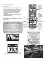
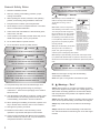
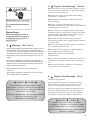
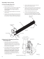
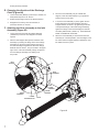
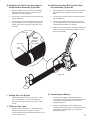
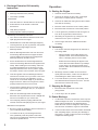
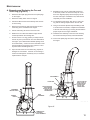
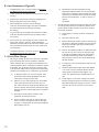
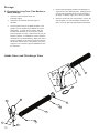
LITTLE WONDER ® Shredding
Models 8221 and 8271
© 2007 Little Wonder, Div. of Schiller-Pfeiffer Inc. All Rights Reserved.
Table of Contents
Important Information
Important Information
A. Introduction
Introduction.................................................................1
Service Information.....................................................1
Special Safety Information.........................................1
Safety Decals.............................................................2
Warnings - “Don’ts”....................................................3
Warnings - “Do’s”....................................................3-4
Engine/ Fuel Warnings - “Don’ts”...............................4
Engine/ Fuel Warnings - “Do’s”..................................4
Hose Assembly...........................................................5
Mounting Shredding TruckLoader Frame..................5
Mounting Boom Arm to Housing Boom Column........6
Mounting Discharge Chute to TruckLoader
Housing.......................................................................6
Changing Direction of Discharge Chute.....................7
Attaching Hose Assembly to Inlet Assembly...................7
Attaching Chain Loop Assembly to Boom
Arm Assembly............................................................8
Attaching Hose Band to Chain Loop Assembly.........8
Adding Oil to Engine...................................................8
Filling Gas Tank..........................................................8
Connecting Battery.....................................................8
Discharge Extension Kit.............................................9
Safety and Warnings
On behalf of everyone at Little Wonder, we would
like to thank you for your purchase of a Little Wonder
Shredding TruckLoader. This professional debris
handling machine was designed to the highest standards
to ensure many hours of uninterrupted service.
General Safety Rules
This manual provides the information necessary for safe
and efficient operation and service. For your safety,
it is critically important that you read and understand
this entire manual before operating your Shredding
TruckLoader.
Assembly Instructions
Specifications:
Operation
Starting the Engine.....................................................9
Vacuuming..................................................................9
Stopping the Engine...................................................9
Debris Blockage.........................................................9
Re-filling the Gas Tank.............................................10
Preparing TruckLoader Unit for Transportation.......10
Oil and Fuel Recommendations / Warnings............10
Maintenance Schedule.............................................11
Removing and Replacing Fan and Talon Ring........12
Liner Replacement...................................................13
Oil and Filter Change...............................................13
Heavy-Duty Air Cleaner............................................14
Spark Plugs..............................................................14
Preparing for Long-Term Storage............................15
Intake Hose and Discharge View.................... 15
Base Unit View................................................. 16
Part Numbers................................................... 17
Warranty.....................................................Back cover
Transportation
Engine Oil and Fuel
Maintenance
Storage
Exploded Assembly Views and Part Numbers
Warranties
1
Model
8221
8271
Dry Weight
500 lbs.
500 lbs.
Max Rpm
3600
3600
B. Service Information
Shredding TruckLoader Unit
Contact your local Little Wonder dealer.
Engine
Contact an authorized Kohler dealer. Dealers are listed
in the Yellow Pages under “Lawn and Garden Equipment
Supplies”, “Lawn Maintenance” or “Lawn Mowers”. Your
dealer will need to know the model and serial number
of your engine. For their location, please consult the
owner’s manual provided with your engine.
C. Special Safety Information
WARNING
DANGER
ATTENTION: THIS SYMBOL POINTS OUT IMPORTANT
SAFETY INSTRUCTIONS
WHEN YOU SEE THIS SYMBOL
HEED ITS WARNING! STAY ALERT!
WARNING
DANGER
TO REDUCE THE POTENTIAL FOR ACCIDENTS,
COMPLY WITH THE SAFETY INSTRUCTIONS IN THIS
MANUAL. FAILURE TO COMPLY MAY RESULT IN
SERIOUS PERSONAL INJURY AND/OR EQUIPMENT
AND PROPERTY DAMAGE.
WARNING
DANGER
THE ENGINE EXHAUST FROM THIS PRODUCT
CONTAINS CHEMICALS KNOWN TO THE STATE OF
CALIFORNIA TO CAUSE CANCER, BIRTH DEFECTS
OR OTHER REPRODUCTIVE HARM.
Safety and Warnings
Keep hands
and feet
away from
air discharge
areas.
Rotating fan
will cause
serious injury.
A. Safety Decals
In order to keep operators of the Shredding TruckLoader
informed regarding safety and/or unit operation, decals
(labels) have been placed on various parts of the unit.
Adherence to the warnings and instructions depicted
or otherwise conveyed in these decals is absolutely
essential to the safe operation of the Shredding
TruckLoader.
Before
performing
any service or
maintenance,
disconnect
spark
plug wire.
Make sure
throttle is in
STOP position.
These decals (labels) must be replaced if they become
illegible due to abrasion, etc.
It is your responsibility to replace the decals (labels)
when they become hard to read. The location of these
decals and their part numbers for ordering are shown on
the picture below.
WARNING
Caution:
Thrown
objects.
Keep
bystanders
away.
DANGER
IMPROPER USE OR CARE OF THIS SHREDDING
TRUCKLOADER, OR FAILURE TO WEAR PROPER
PROTECTION CAN RESULT IN SERIOUS INJURY.
READ AND UNDERSTAND THE RULES FOR
SAFE OPERATION AND ALL INSTRUCTIONS
IN THIS MANUAL.
Always wear
eye, ear and
breathing
protection.
P/N 600602
Warning Label
Read and
understand
the Owners
Manual. Store
your Owners
Manual in a
safe place.
WEAR HEARING, EYE, AND BREATHING
PROTECTION.
Caution: Hot Surface
P/N 720609
Caution: Thrown objects.
Keep bystanders away.
2
General Safety Rules
WARNING
Do not use the Shredding TruckLoader if
the muffler is defective or missing.
1. Read and understand manual.
2. Wear eye, hearing, and breathing protection, proper
clothing and footwear.
3. While operating the machine, maintain a safe operating
position, secure footing and good balance at all times.
4. Keep area clear of children, pets and bystanders.
5. Never attempt to use an incomplete machine or one fitted
with an unauthorized modification.
6. Avoid contact with and inhalation of harmful fluids, gases,
mists, fumes, and dust.
7. Check operation of the safety interlock switch daily. Do not
defeat interlock system; it is for your protection.
8. Do not allow children to operate machine.
9. Do not override or remove any safety devices.
WARNING
DANGER
10. Fan coasts after the engine is turned off.
WARNING
DANGER
11. Rotating fan. Don’t attempt to remove
materials from intake or discharge when
A.
Don’t install or remove components
while Shredding TruckLoader is running.
Turn off engine to make changeover.
Be sure throttle is in the “slow” position,
ignition key is in the “off” position and
the Shredding TruckLoader has come
to a complete stop. Remove the spark
plug wires from the spark plug before
removing material.
Don’t point the Shredding TruckLoader
discharge chute in the direction of
people, cars, glass or anything that
could be injured or damaged by blown debris.
Don’t attempt to repair Shredding TruckLoader. Have repairs made
by a qualified Little Wonder dealer or repairman. See that only Little
Wonder and recommended engine manufacturer replacement parts are
used.
13. Keep hands away from hose inlet and discharge chute.
14. Disconnect spark plugs before doing any cleaning or
maintenance – There are two spark plugs on the machine.
Disconnect both.
15. If the Shredding TruckLoader is mounted on a trailer, make
sure that the driver of the towing vehicle has the operator
of the Shredding TruckLoader in full view at all times.
16. When operating the Shredding TruckLoader, operator must
stay to the side of the machine, never in front or behind
17. Wear gloves to protect your hands.
18. Beware that the machine is loud and during normal
operation it may interfere with speech communication.
19. Check mounting hardware daily! Beware of the possibility
that the machine may overturn, fall, or tip over because of
unexpected movement of the vehicle.
3
WARNING
DANGER
Do not smoke when filling fuel tank
DANGER
12. DO NOT operate unit if excessive vibration
occurs; shut engine off immediately! Remove
spark plug wires and check for damaged
impeller, loose impeller bolt, loose impeller
key, or lodged foreign objects.
Warnings - “Don’ts”
Don’t attempt to remove materials from
intake or discharge when Shredding
TruckLoader is running, or fan is
rotating.
unit is running, or fan is rotating.
WARNING
DANGER
Don’t leave the engine running while the Shredding
TruckLoader is unattended.
Don’t store, spill, or use gasoline near flames or spark
B.
Warnings - “Do’s”
Always dress properly. Do not wear loose clothing or jewelry.
They can be caught in moving parts. Use of sturdy gloves, nonskid footwear and safety glasses are recommended. Always
wear ear protectors where possible. Use respirator mask to
avoid breathing dust.
Always stay alert. Watch what you are doing and use common
sense. Do not operate Shredding TruckLoader when fatigued.
Always keep hands away from air intake and air discharge
chute.
Always maintain and examine Shredding TruckLoader with
care. Follow maintenance instructions given in unit and engine
manuals.
C.
Engine/ Fuel Warnings - “Don’ts”
Don’t fuel engine or check fuel while smoking or near an
open flame or other ignition source. Stop engine and be
sure it is cool before refueling.
Don’t leave the engine running while the Shredding
TruckLoader is unattended.
Don’t transport the Shredding Truckloader while the
engine is running.
Don’t start, run this TruckLoader indoors, or in an
improperly ventilated area as poisonous carbon monoxide
and other gasses are emitted.
Don’t run engine when electrical system causes spark
outside the cylinder. During periodic checks of the spark
plug, keep plug a safe distance from cylinder to avoid
ignition of evaporated fuel from cylinder.
Don’t check for spark with spark plug or plug wire
removed and grounded. Use an approved tester. Sparks
can ignite fumes.
B.
Warnings - “Do’s” Con’t.
Always store Shredding TruckLoader indoors. When not in use,
store Shredding TruckLoader indoors in a sheltered area (a
dry place) where it is not accessible to children. The Shredding
TruckLoader, as well as fuel, should not be stored in a house.
Keep throttle in the “slow” position and ignition key in the “off”
position.
Always be sure Shredding TruckLoader is fully assembled.
Never operate Shredding TruckLoader without all guards and
deflectors in place. Ensure that all nuts, bolts and screws are
installed and properly tightened.
Always keep the throttle in the “slow” position when
not in use.
Always keep a safe distance between two or more operators
when working together simultaneously.
Don’t run engine when the odor of gasoline is present or
other explosive conditions exist.
Don’t operate the unit if gasoline is spilled. Clean up
spill completely before starting engine.
Don’t refuel indoors or in an improperly
ventilated area.
Don’t operate your Shredding TruckLoader if there is an
accumulation of debris around the muffler, and cooling
fins.
Don’t touch hot mufflers, cylinders or cooling fins as
contact may cause serious burns.
D.
Engine/ Fuel Warnings - “Do’s”
Always use fresh gasoline.
WARNING
DANGER
IF THE SHREDDING TRUCKLOADER IS USED
IMPROPERLY OR SAFETY PRECAUTIONS ARE NOT
FOLLOWED, THE USER RISKS SERIOUS INJURY TO
THEMSELVES AND OTHERS.
READ AND UNDERSTAND THE FOLLOWING BEFORE
ATTEMPTING TO OPERATE THIS
SHREDDING TRUCKLOADER.
Always handle fuel with care; it is highly flammable.
Never add fuel to a machine with a running or hot
engine. Do not inhale fuel fumes as they are toxic.
The use of spark arrestor mufflers is required by law in
the state of California (Section 4442 of the California
Public Resources Code), as well as in other states or
municipalities. Federal laws apply on federal lands.
WARNING
DANGER
HANDLE FUEL WITH CARE. IT IS HIGHLY
FLAMMABLE. FUELING A HOT ENGINE OR NEAR
AN IGNITION SOURCE CAN CAUSE A FIRE AND
RESULT IN SERIOUS PERSONAL INJURY AND/ OR
PROPERTY DAMAGE.
4
Assembly Instructions:
A. Hose Assembly (Figure #1)
1. Remove the Hose from the box.
5. Insert the Intake Nozzle into the end of the hose
opposite the hose flange as shown.
2. With the assistance of a second person, hold the hose
at both ends and stretch it out as far as possible.
This will maximize the hose length and open the
internal diameter.
6. Using the second Hose Clamp, secure the hose to the
Intake Nozzle by wrapping the clamp around the hose
portion covering the Intake Nozzle and tighten.
3. Insert the Hose Flange Assembly into one of the open
ends as shown.
4. Using one of the Hose Clamps, secure the hose to the
Hose Flange Assembly by wrapping the clamp around
the hose portion covering the Hose Flange and tighten.
7. Install the Intake Nozzle Handle as shown.
8. To secure the Intake Nozzle Handle to the Intake
Nozzle, insert the (4) Bolts (64262-020) and (4) Nuts
(64229-03) that have been provided for the installation.
HOSE FLANGE
ASSEMBLY
HOSE
INTAKE NOZZLE
HANDLE
HOSE CLAMP
Figure #1
INTAKE NOZZLE
HOSE CLAMP
BOLT
NUT
B. Mounting the Shredding TruckLoader
Frame (Figure #2)
1. There are four holes in the TruckLoader frame
deck through which the unit can be secured to an
appropriate mounting surface. For your convenience,
(4) Bolts (64123-234) and (4) Nuts (64268-07) have
been provided for the installation.
2. For the purpose of lifting your unit, two options have
been provided for you. The first option is a lifting
lug found near the engine muffler mounted on the
backside of the Housing Assembly. This lug has
been designed to hold a maximum of 500 pounds.
The second option is the lifting bars, which are
incorporated in the frame and found on either side
of the Housing Assembly.
FRAME DECK MOUNTING HOLES
5
FIGURE
LIFTING#1LUG
FRAME
LIFTING BARS
Figure #2
C. Mounting the Boom Arm Assembly to the
Housing Boom Column (Figure #3)
1. Slide a Thrust Washer (720428) onto the shaft of the
Boom Column Assembly.
5. Secure the Boom Arm Assembly and Washers to the
shaft with a Lock Nut (720580).
2. Apply some #2 lithium based grease to the shaft of the
Boom Column.
6. As needed, insert some #2 lithium based grease
through the grease fitting provided in the Boom Arm
Assembly.
3. Install the Boom Arm Assembly (720285.17) onto the
shaft of the Boom Column Assembly.
7. Install Linch Pin (720437) as shown.
4. Slide a second Thrust Washer (720428) onto the shaft
of the Boom Column Assembly.
BOOM COLUMN
LOCK NUT
THRUST WASHER
BOOM ARM ASSEMBLY
GREASE FITTING
LINCH PIN
Figure #3
THRUST WASHER
ROTATE TO
DESIRED POSITION
FIGURE #3
D. Mounting the Discharge Chute to the
TruckLoader Housing (Figure #4)
1. Slide the Discharge Clamp Ring (720262.17) over the
Discharge Chute and down onto its flange.
2. Lift the Discharge Chute’s flange (720200) with the
Discharge Clamp Ring (720262.17) and place on top
of the Transition Discharge Tube’s flange (720461) as
shown.
3. Align the mounting holes of the Discharge Clamp Ring
(720262.17) with the bolts on the Transition Discharge
Tube’s flange (720462.10).
DISCHARGE
CLAMP RING
DISCHARGE CHUTE
KNOB
NUT
Figure #4
4. Secure the Discharge Clamp Ring (720262.17) to the
Transition Discharge Tube’s flange (720462.10) by
lightly fastening a Nut (64229-03) and Knob (38524) in
an alternating pattern as three of each are provided.
5. Position the Discharge Chute into the receiver box of
the transport vehicle and tighten down the Nuts and
FIGURE #4
6
Knobs previously installed.
E. Changing the direction of the Discharge
Chute (Figure #4)
3. Since the Hose Assembly may be rotated 360
degrees, orient the Intake Nozzle to your preferred
position and lock it in place.
1. Loosen the Knobs (38524) by hand and, if needed, the
Nuts (64229-03) with a 1/2” wrench.
2. Rotate the Discharge Chute to the desired position.
4. To lock the Hose Assembly in place, tighten the two
knobs attached to the Flange Retainer Plate and
Flapper Retainer as shown. By tightening the knobs,
it will push the flange of the Hose Flange Assembly
against the flange of the Inlet Assembly and activate
the Safety Switch Plate (720234.17). THIS MUST BE
DONE TO OPERATE THIS UNIT.
3. Retighten the Knobs by hand and the Nuts, if
loosened, with the 1/2” wrench.
F. Attaching the Hose Assembly to the Inlet
Assembly (Figure #5)
1. Loosen the knob and rotate the Flapper Retainer
(720258.10) to allow the Inlet Flapper to be lifted
upward.
5. When the Hose assembly is removed from the Inlet
Assembly for unit transportation, the Inlet Flapper must
be closed and the Flapper Retainer (720258.10) must
be rotated to lock it in place.
2. With the Inlet Flapper held upward, install the Hose
Assembly by inserting the flange of the Hose Flange
Assembly into the space (gap) between the face of
the Inlet Assembly Flange and the back face Flange
Retainer Plate as shown. The pin located in the upper
right corner of the Inlet Assembly Flange will prevent
the Hose Flange Assembly from sliding out of
this pocket.
INLET
FLAPPER
PIN
INLET
ASSEMBLY
HOSE
FLANGE
ASSEMBLY
FLAPPER
RETAINER
HOSE
ASSEMBLY
FLANGE
RETAINER PLATE
KNOB
Figure #5
7
FIGURE #5
G.Attaching the Chain Loop Assembly to
the Boom Arm Assembly (Figure #6)
H. Attaching the Hose Band to the Chain
Loop Assembly (Figure #6)
1. Slip the threaded end of the Chain Loop Assembly
(720290) through the hole found at the end of the
Boom Arm Assembly (720285.17).
1. After wrapping the Hose Band around the Hose, insert
the Bolt (64123-61) through the holes in the Hose
Band.
2. Once through, secure the Chain Loop Assembly with
the Nut (64229-05).
2. Once through, secure the Bolt in the Hose Band with
the Nut (64229-02).
3. The level position of the Hose Assembly to the Inlet
Flange Assembly can be controlled by adjusting the
position of the Nut on the thread of the Chain Loop
Assembly.
3. Attach the Hose Band to the Chain Loop Assembly
by connecting the chain to the Bolt (64123-61) via the
supplied Carabiner Quick Clip (720487)
4. Make sure the Hose Band is in the proper position with
respect to the Hose to allow free movement with the
Boom Arm Assembly.
NUT (720576)
BOOM ARM
ASSEMBLY
CHAIN LOOP
ASSEMBLY
NUT (720585)
BOLT (720588)
HOSE
BAND
Figure #6
F IGURE #6
I. Adding Oil to the Engine
1. Fill the crankcase with the proper oil to the “F” mark
found on the dipstick. The oil recommendations
are found in the Engine Oil and Fuel section of this
manual.
J. Filling the Gas Tank
1. Fill the tank with the proper fuel. Take extra caution
when filling the tank not to over-fill it. The fuel
recommendations are found in the Engine Oil and Fuel
section of this manual.
K. Connecting the Battery
1. Connect the Red Battery Cable (720339) found
connected to the engine starter to the positive terminal
of the battery with the Bolt (64123-114) and Nut
(64268-01) provided.
2. Connect the Black Battery Cable (720340) found
connected to the engine block to the negative terminal
of the battery with the Bolt (64123-114) and Nut
(64268-01) provided.
8
L. Discharge Extension Kit Assembly
Instructions
Contents Included in Kit:
A. Starting the Engine
1. Discharge Extension Hose (720436)
1. Check the oil level. Add oil if necessary.
2. Hose Clamp (720388)
2. Check the air cleaner for dirty, loose, or damaged
parts. Clean or replace parts as necessary.
Tools Needed:
1. 9/16” Box Wrench or Socket Wrench w/ 9/16” Socket
2. Socket Wrench w/ 3/8” Socket or Flat Head
Screw Driver
3. Check the air intake and cooling area for dirt or debris
and clean as necessary.
4. Move the choke control lever to the “choke” position.
3. Utility Knife (if required)
5. Move the throttle control lever to the middle position.
4. Heavy Duty Wire Cutters (if required)
6. Turn the ignition key clockwise to start the engine. As
soon as the engine starts, release the key.
Disassembly and Assembly Instructions:
1. Turn off the TruckLoader and disconnect both of the
spark plug wires from the engine.
2. Disassemble the TruckLoader Discharge Flapper by
removing the knob, (2) nuts, (2) washers, and (3) bolts.
3. Remove the Discharge Flapper from the
Discharge Nozzle.
4. Slide the Discharge Extension Hose over the end of
the Discharge Nozzle where the Flapper has been
removed. Make sure the Hose has overlapped the
Discharge Nozzle by at least 6 inches.
5. Secure the attachment of the Discharge Extension
Hose to the Discharge Nozzle with the supplied Hose
Clamp. When installing the Hose Clamp, make sure
it is positioned between the 1st and 2nd coil of the
Discharge Extension Hose. Once in position, tighten
the clamp to ensure a firm connection of the two parts.
6. Insert the opposite end of the Discharge Extension
Hose into the receiver box on your truck. In the event
the Hose is too long for your application, you can
choose to cut it to a shorter length. If you shorten the
length of this hose, make sure enough hose is left to
properly install and secure it into the truck.
7. Once the Hose is properly fit into your truck, secure it
in place with a rope, bungee cord, etc., as required to
secure it in place.
8. Make sure the Discharge Nozzle and Discharge
Extension Hose is positioned to ensure a straight flow
from the TruckLoader into your receiver box.
9. Once everything has been properly positioned and
secured, reconnect both spark plug wires on your engine.
Maintenance and Operation:
1. Be sure to check the positioning and all connections of
your TruckLoader before starting.
2. To increase the life of your Discharge Extension
Hose, periodically rotate the position of this hose.
This can be accomplished by repeating the Assembly
instructions specified above.
9
Operation:
7. After letting the engine warm up, slowly move the
choke lever to the “open” run position.
8. See the engine manual for additional information
on starting.
B. Vacuuming
1. This machine has been designed for two methods of
vacuuming debris.
•
With the handles of the Intake Nozzle in the
operator’s hands, move the Nozzle back and
forth in a sweeping motion over the debris.
•
Rotate the Hose Assembly 90 degrees at the
Inlet to allow the Intake Nozzle to lay sideways
on the ground. By placing the Nozzle in this
position, debris can be raked into the Nozzle by
the operator.
2. While large amounts of debris can be vacuumed
quickly with this machine, caution must be taken to
avoid blocking the airflow into the Nozzle.
3. To increase the life of your Hose, periodically rotate
the Intake Nozzle with respect to the Hose. This will
allow the hose to wear more evenly.
C. Stopping the Engine
1. Move the throttle control lever to the “turtle”
(slow) position.
2. Turn the key to the “off” position.
D. Debris Blockage
1. If a decrease in suction is experienced, there may be a
debris blockage in the hose. To remove this blockage,
simply grab the handles of the Intake Nozzle and
stretch the hose out into a straight line with respect to
the Inlet of the unit while the engine is at full throttle.
2. In the event the suction of the hose remains decreased
after completing step #1, there may be a blockage in
the housing. In order to inspect the unit for blockages,
complete the following steps:
a) Turn off the engine and wait until all moving
parts have come to a complete stop.
b) Disconnect the spark plug wires from the spark
plugs on the engine.
c) Remove the Hose Assembly from the Inlet
Flange Assembly. With this removed, open
the Inlet Flapper and remove any debris that
is clogging the housing. CAUTION SHOULD
BE USED WHEN CLEARING DEBRIS FROM
INSIDE THE HOUSING. GLOVES SHOULD BE
WORN AS SHARP EDGES ON THE FAN, THE
TALON RING, OR IN THE DEBRIS MAY BE
PRESENT.
d) Remove the Discharge Chute from the
Transition Discharge Tube’s flange. With
the Chute removed, inspect the Transition
Discharge part of the housing and remove any
debris clogging this area. CAUTION SHOULD
BE USED WHEN CLEARING DEBRIS FROM
INSIDE THE HOUSING. GLOVES SHOULD BE
WORN AS SHARP EDGES ON THE FAN, THE
TALON RING, OR IN THE DEBRIS MAY BE
PRESENT.
e) Inspect the Discharge Chute for debris and
remove any debris clogging this area.
f) In order to re-assemble the removed parts,
please refer to the Assembly Instructions
found in this manual. After the unit is
re-assembled, reconnect the spark plug wires
and resume operation.
E. Re-filling the Gas Tank
5. Make sure the Chain Loop Assembly cannot make
contact with anything other than the Boom Arm
Assembly. If necessary, use a bungee cord to secure
it.
6. Remove the Hose Assembly from the Inlet Flange
Assembly.
7. Close the Inlet Flapper and rotate the Flapper Retainer
(720257) to allow the Flapper to be secured by
tightening the knob.
8. Remove the Discharge Nozzle from the
TruckLoader Housing.
9. Secure all the removed TruckLoader parts in the bed
of the vehicle with the proper rope or hardware.
10. Before moving a trailer containing the TruckLoader
unit, be sure that everything is properly secured for
road travel and that safety towing chains are properly
attached to the vehicle.
Engine Oil and Fuel:
A. Oil Recommendations: using the proper type and
weight of oil in the crankcase is extremely important.
It is also important to check oil daily and change oil
regularly. Failure to use the correct oil, or using dirty
oil, causes premature engine wear and failure.
1. Oil Type: Use high quality detergent oil of API
(American Petroleum Institute) service class SC;
SH, SJ or higher. Select the viscosity based on
the air temperature at the time of operation as
shown in the following table.
RECOMMENDED SAE VISCOSITY GRADES
1. If the unit was being operated, make sure the
engine has been turned “off” and is allowed to cool off
completely.
2. Once you have determined the engine is cool, fill
the tank with the proper fuel. Take extra caution
when filling the tank not to over-fill it. The fuel
recommendations are found in the Engine Oil and Fuel
section of this manual.
Transportation:
A. Preparing the TruckLoader Unit for
Transportation
1. Make sure the engine is off.
2. Disconnect the Carabiner (720487) from the hose band.
3. Attach the Carabiner to the chain link closest to the
Boom Arm Assembly.
4. Rotate the Boom Arm Assembly toward the vehicle to
allow the locking bosses on the Arm and Column to
line up. Once the bosses are aligned, insert the Linch
Pin (720437) through the hole and snap the ring over
the boss to secure.
10W-
5W-20, 5W-30
Kohler “Command”
*Use of synthetic oil having 5W-20 or 5W-30 rating is acceptable, up to 40º.
**Synthetic oils will provide better starting in extreme cold (below -10ºF).
NOTE: Using other than service class SG, SH, SJ or higher
oil or extending oil change intervals longer than recommended
can cause engine damage. A logo or symbol on oil containers
identifies the API service class and SAE viscosity grade.
B. Fuel Recommendations:
1. Fuel Type: For best results use only clean,
fresh, unleaded gasoline with a pump sticker
octane rating of 87 or higher. In countries using
the Research method, it should be 90-octane
minimum. Unleaded gasoline is recommended
as it leaves less combustion chamber deposits
and reduces harmful exhaust emissions.
Leaded gasoline is not recommended and
must not be used on models where exhaust
emissions are regulated.
10
a. Gasoline/Alcohol blends: Gasohol
(up to 10% ethyl alcohol, 90%
unleaded gasoline by volume) is
approved as a fuel for Kohler engines.
Other gasoline/alcohol blends are not
approved.
2. Fuel Warnings: Gasoline is extremely flammable
and its vapors can explode if ignited. Store
gasoline only in approved containers, in wellventilated, unoccupied buildings, a way from
sparks or flames. Do not fill the fuel tank while
the engine is hot or running, since spilled fuel
could ignite if it comes in contact with hot parts
or sparks from ignition. Do not start the engine
near spilled fuel. Never use gasoline as a
cleaning agent.
b. Gasoline/Ether blends: Methyl Tertiary
Butyl Ether (MTBE) and unleaded
gasoline blends (up to a maximum of
15% MTBE by volume) are approved
as a fuel for Kohler engines. Other
gasoline/ether blends are not approved.
a. To minimize gum deposits in fuel system
and to insure easy starting, do not use
gasoline left over from the previous
season.
b. Do not add oil to the gasoline.
c. Do not overfill the fuel tank.
d. Filler neck should not contain fuel.
Maintenance Schedule:
FREQUENCY
Daily or Before Starting the Engine
Every 5 hours of Usage
Every 100 hours of Usage
MAINTENANCE REQUIRED
•
Fill the fuel tank
•
Check the engine oil level and fill, if needed,
to the proper level
•
Check the air cleaner for dirty, loose,
or damaged parts
•
Check the air intake and cooling areas for debris
and clean as necessary
•
Check the operation of the safety switch
•
Check for excessive vibration, loose, or damaged parts
on the unit
•
Inspect and clean the Hose and Discharge Nozzle
of clogging debris
•
Inspect the condition of all warning labels and replace
if necessary
•
Inspect for excessive vibration, loose, or damaged
parts on the unit
•
Check the engine oil level and fill, if needed, to the proper
level
•
Change the engine oil as instructed in this manual
•
Remove the cooling shrouds of the engine and
clean the cooling areas of dust, dirt, or debris
•
Change the engine oil filter as instructed in
this manual
•
Check the engine spark plugs condition and gap
•
Service the engine’s Heavy-Duty Air Cleaner, including
replacing the Main Element, as instructed in this manual
•
Service the engine’s Heavy-Duty Air Cleaner, including
replacing the Inner Element, as instructed in this manual
Every 200 hours of Usage
Every 250 hours of Usage
Every 500 hours of Usage
11
See the Kohler Engine Owner’s Manual for additional required maintenance.
Maintenance:
A. Removing and Replacing the Fan and
Talon Ring (Figure #7)
2. Disconnect safety switch wire from engine.
9. Reinstall the Fan onto the crankshaft and orient it
to the same position as removed in Step #6. Once
the Fan is aligned properly with the keyways of the
Fan hub and engine crankshaft in line, slide the Fan
completely onto the crankshaft.
3. Unbolt and Remove the Inlet Assembly from the face
of the Housing.
10. To reinstall the Talon Ring, align the “D” hole in the
ring with the mating shape found on the Fan hub.
4. Remove the bolt (64123-160) securing the Fan and
Talon Ring to the crankshaft of the engine.
5. Pull the Talon Ring off the face of the Fan hub.
11. Using a new fan bolt (64123-160) and adding a dab
of Loctite 242 to it’s threads, complete the installation
of the Fan and Talon ring by securing the bolt with the
proper torque into the engine crankshaft.
6. Rotate the Fan to allow the blades to align with the
notches provided in the Housing face.
12. Install the Inlet Assembly to the face of the Housing
and secure with the previously removed hardware.
7. Thread a 3/4-16 x 5” long grade 5 (or better) bolt into
the hub to jack or push the Fan from the crankshaft of
the engine. (The Little Wonder #910505 jacking screw
is recommended.) **Take note of the orientation of the
fan with respect to the keyway upon removal. This is
important when reinstalling the Fan.**
13. Connect the spark plug wires to the spark plugs on
the engine.
1. Disconnect the spark plug wires from the spark plugs
on the engine.
8. Upon removal of the Fan and Talon Ring, inspect for
damaged or worn blades. If the Fan or Talon Ring is
found to be damaged or excessively worn, it should be
replaced with a new part.
CHAMFERED
EDGE OF LINER
FAN ASSEMBLY
LINER
HARDWARE
RUBBER
LINER
USE HOLE IN FAN
BACK PLATE TO
ALIGN FAN HUB
KEYWAY WITH
KEY ON THE
CRANK SHAFT
TALON RING
CHAMFERED
EDGE OF LINER
ALIGN FAN BLADE
WITH HOUSING
NOTCH FOR FAN
INSTALLATION
AND REMOVAL
FAN ASSEMBLY
RUBBER
LINER
LINER
HARDWARE
REMOVE NUTS
TO DETACH
INLET ASSEMBLY
BOLT
(720572)
TALON RING
ALIGN FAN BLADE
WITH HOUSING
NOTCH FOR FAN
INSTALLATION
Figure
#7
AND REMOVAL
REMOVE NUTS
TO DETACH
INLET ASSEMBLY
USE HOLE IN F
BACK PLATE T
ALIGN FAN HU
KEYWAY WITH
KEY ON THE
FIGURE
CRANK #7
SHAFT
BOLT
(720572)
12
FIGUR
B. Liner Replacement (Figure #7)
1. Complete Steps 1 thru 7 found in section A (Removing
and Replacing the Fan and Talon Ring).
2. Unbolt and remove the hardware securing the Liner to the
Housing.
3. Remove the Liner from the housing by wrapping it and
pulling it through the front of the housing.
4. When installing the new Liner into the Housing,
make sure the chamfered edge of the liner is installed in
the vertical position at the discharge opening of
the housing.
5. As you position the Liner against the wall of the Housing,
make sure the holes of the liner line up with the slots in
the Housing.
6. Secure the Liner to the Housing (one hole at a time) with
the 10 bolts, washers, and nuts. When installing the
hardware, insert the bolts through the inside surface of the
liner and install the washers and nuts to the outside face
of the Housing.
7. Complete Steps 8 thru 13 found in section A (Removing
and Replacing the Fan and Talon Ring).
C. Oil and Filter Change
1. Oil Change: Change oil after every 100 hours of operation
(more frequently under severe conditions). Refill with
service class SG, SH, SJ or higher oil as specified in the
“Viscosity Grades” above. Change the oil while the engine
is still warm. The oil will flow more freely and carry away
more impurities. Make sure the engine is level when filling,
checking, and changing the oil. Change the oil as follows:
a) To keep dirt, debris, etc., out of the engine, clean
the area around the oil fill cap/dipstick and drain
valve before moving to the next step.
b) Attach a 1/2” I.D. hose to the fitting on the oil drain
valve. Place the other end of the hose in an oil
pan. Next, remove the oil fill cap and dipstick, then
open the oil drain valve (counter-clockwise) to begin
drainage. Be sure to allow ample time for complete
drainage.
c) Once all the oil has drained, close the valve
(clockwise) and remove the hose.
d) Fill the crankcase, with new oil of the proper type,
to the “F” mark on the dipstick. Refer to “Oil Type”
on page 11. Always check the level with the dipstick
before adding more oil.
13
e) Reinstall the oil fill cap and tighten securely.
Reinstall the dipstick. NOTE: To prevent extensive
engine wear or damage, always maintain the proper
oil level in the crankcase. Never operate the engine
with the oil level below the “L” mark or over the “F”
mark on
the dipstick.
2. Oil Filter Change: Replace the oil filter at least every other
oil change (every 200 hours of operation). Always use a
genuine Kohler oil filter, Part No. 12 050 OI-S. Replace
the oil filter as follows:
a) Follow steps A to C from the above “Change Oil”
section.
b) Allow the oil filter to drain.
c) Before removing the oil filter, clean the area around
the oil filter to keep dirt and debris out of the engine.
Remove the old filter. Wipe off the surface where
the oil filter mounts.
d) Place a new replacement filter in a shallow pan with
the open end up. Pour new oil, of the proper type,
in through the threaded center hole. Stop pouring
when the oil reaches the bottom of the threads.
Allow a minute or two for the oil to be absorbed by
the filter material.
e) Put a drop of oil on your fingertip and wipe it on the
rubber gasket.
f) Install the replacement oil filter to the filter adapter
or oil cooler. Turn the oil filter clockwise until the
rubber gasket contacts the filter adapter or oil
cooler, then tighten the filter an additional 2/3 to 1
turn.
g) Follow steps 4-5 from above “Change Oil” section.
Start the engine and check for oil leaks. Correct any
leaks before placing the engine into service. Check
oil level to be sure it is up to but not over the “F”
mark.
D. Heavy-Duty Air Cleaner
E. Spark Plug
1. Every 250 hours of operation (more often under
extremely dusty or dirty conditions), replace the main
paper element and check inner element. Follow
these steps.
a) Unhook the two retaining clips and remove the
end cap from the air cleaner housing.
b) Pull the air cleaner element out of the housing.
See Removing Elements Figure.
c) After the main element is removed, check the
condition of the inner element. It should be
replaced whenever it appears dirty, typically
every other time the main element is replaced.
Clean the area around the base of the inner
element before removing it, so dirt does not get
into the engine.
1. Every 200 hours of operation, remove the spark plugs,
check condition, and reset the gap or replace with new
plugs as necessary. The standard spark
plug is a Champion@ RC12YC (Kohler Part No.
12 132 02-S). A high-performance spark plug,
Champion@ Premium Gold 2071 (used on Pro
Series engines, Kohler Part No. 12 132 06-S) is also
available. Equivalent alternate brand plugs can also
be used.
a) Before removing the spark plug, clean the area
around the base of the plug to keep dirt and
debris out of the engine.
b) Remove the plug and check its condition.
Replace the plug if worn or reuse is
questionable. NOTE: Do not clean the spark
plug in a machine using abrasive grit. Some grit
could remain in the spark plug and enter the
engine causing extensive wear and damage.
c) Check the gap using a wire feeler gauge. Adjust
the gap to 0,76 mm (0.030 in,) by carefully
bending the ground electrode.
Removing Elements Figure
Heavy-Duty Air Cleaner
Assembly Figure
d) Reinstall the spark plug into the cylinder head.
Torque the spark plug to 24.4-29J N-m
(18-22 ft. lb,). 4. Reinstall the spark plug into the
cylinder head. Torque the spark plug to 24.4-29J
N-m(18-22 ft. lb,).
d) Do not wash the paper element and inner
element or use pressurized air, this will damage
the elements. Replace dirty, bent or damaged
elements with new genuine Kohler elements as
required. Handle new elements carefully; do not
use if the sealing surfaces are bent or damaged.
e) Check all parts for wear, cracks or damage.
Replace any damaged components.
f)
Install the new inner element, Kohler Part No. 25
083 04-S followed by the outer element, Kohler
Part No. 25 083 01-S. Slide each fully into place
in the air cleaner housing.
g) Reinstall the end cap so the dust ejector valve
is down and secure with the two retaining clips.
See Heavy-Duty Air Cleaner Assembly Figure.
14
Storage:
4. Remove the spark plugs and add one tablespoon of
engine oil into each spark plug hole. Install plugs and
ground spark plug leads-do not connect the leads to
the plugs. Crank the engine two or three revolutions.
A. Preparing for Long-Term (Two Months or
More) Storage
1. Clean the exterior surfaces of the unit
(including engine).
5. Store the unit and all of it’s components in a clean, dry,
well ventilated, non-child accessible, sheltered area
that is out of sun light and high ambient temperatures.
2. Change the Oil and Filter while the engine is
still warm.
3. The fuel system must be completely emptied, or the
gasoline must be treated with a stabilizer to prevent
deterioration. To empty the fuel system, drain the
fuel tank and carburetor or run the engine until the
tank and system are empty. Drained fuel may only be
stored for 30 days. If a stabilizer is chosen, follow the
manufacturer’s recommendation by adding the correct
amount of additive for the amount of fuel to be stored.
Fill the tank with this clean, fresh gasoline and run the
engine for 2 to 3 minutes to get the stabilized fuel into
the carburetor.
Intake Hose and Discharge View
79
80
65
39
78
66
72
74
69
73
70
73
76
71
67
15
75
76
76
44
34
45 X9
30
47
64
39
34
55
62
63
60
57
61
56
59
50 X2
52
58 X2
49
48
51
34
53
43
54
42
37
41
28
38
31
40
81
39 X2
10
29 X4
77
36 X4
34 X10
33 X10
23
39 X2
21
24
35
32
22
X10
8 X4
25 X2
3
9 X4
26 X4
27
2
10 X2
6 X4
4
5 X4
14 X4
1
7 X4
11
13 X4
12 X4
10 X4
15
16
20 X4
17
19
18
Base Unit View
16
Model #8221 & 8271 Part Numbers
Balloon Item # Part #
Description
8221 Qty.
1
720903
22 HP KOHLER ENGINE
1
1
720904
27 HP KOHLER ENGINE
-
2
720483
OIL DRAIN VALVE
1
3
64163-34
3/8” SQ. x 3” LG KEY
1
4
720451.17
PAINTED SKID FRAME
1
5
64123-234
3/4-10 x 4” LG HEAVY HEX CAP SCREW
4
6
64268-07
3/4-10 GRADE G LOCK FLANGE NUT
4
7
720279
1-1/4” ROUND TUBE PLUG
4
8
64123-82
WASHER, FLAT .406 X 1.411 X 9GA
4
9
64213-31
3/8 SAE FLAT WASHER
4
10
64141-4
3/8-16 WIZ NUT
4
11
720491
GAS TANK
1
12
64123-75
3/8” x 1-3/4” LG. GR 8 HEX BOLT
4
13
64163-87
3/8 SAE GRADE 8 FLAT WASHER
4
14
64229-03
3/8-16 NYLON INSERT NUT
4
15
720296
GAS TANK FUEL CAP
1
16
720490-007
GAS TANK OUTLET FITTING
1
17
4162977
5” FUEL LINE HOSE
1
18
13-021
KOHLER FUEL FILTER
1
19
4162977-015
30” FUEL LINE HOSE
1
20
88042N
FUEL LINE HOSE CLAMP
4
21
108055
HEAVY DUTY 12V BATTERY
1
22
720465
BATTERY HOLD DOWN
1
23
720469
BLACK BATTERY CABLE
1
24
720468
RED BATTERY CABLE
1
25
64123-114
1/4-20 x 1” LG. HEAVY HEX CAP SCREW
2
26
64268-01
1/4-20 LOCK FLANGE NUT
4
27
910503
BOLT, SERRATED FLANGE, 5/16-24 x 3/4” LG, LOCKING PATCH
1
28
720460.10
PAINTED HOUSING ASSEMBLY
1
29
64139-18
3/8-16 x 1-1/4” LG. GR 5 HEX BOLT
4
30
64255-01
INSERT-RIVNUT 5/16-8
1
31
720416
RUBBER LINER
1
32
720592
5/16-18” x 1” LG. GR 5 HEX BOLT
10
33
64163-55
5/16 SAE GRADE 8 FLAT WASHER
10
34
64229-02
5/16-18 NYLON INSERT NUT
13
35
720462.10
PAINTED TRANSITION DISCHARGE TUBE
1
36
64018-9
5/16-18 x 3/4” LG SQ. NECK CARRIAGE BOLT
4
37
720437
LINCH PIN w/ LAYNARD
1
38
64163-29
11/32” I.D. 1 1/4” O.D. WASHER
7
39
64268-02
5/16-18 GRADE G LOCK FLANGE NUT
11
40
720440
FAN HUB SPACER
1
41
720470
22HP BALANCED FAN ASSEMBLY
1
41
720472
27HP BALANCED FAN ASSEMBLY
-
42
720362
TALON RING ASSEMBLY
1
43
64123-160
5/8-18 x 3” LG. GR 8 HEAVY HEX CAP SCREW
1
44
720364.10
12” INLET ASSEMBLY
1
44
720368.10
14” INLET ASSEMBLY
-
45
64141-6
5/16-18 WIZ NUT
9
46
-----------
----------------------------------------------------------------------
-
47
720373.17
12” HOSE FLANGE RETAINER PLATE
1
47
720374.17
14” HOSE FLANGE RETAINER PLATE
-
48
720509
5/16 WASHER
2
17
8271 Qty.
1
1
1
1
4
4
4
4
4
4
1
4
4
4
1
1
1
1
1
4
1
1
1
1
2
4
1
1
4
1
1
10
10
13
1
4
1
7
11
1
1
1
1
1
9
1
2
Model #8221 & 8271 Part Numbers
Balloon Item # Part #
Description
49
720258.10
FLAPPER RETAINER
50
154
5/16-18 FEMALE THREADED KNOB
51
720234.17
PAINTED SWITCH PLATE
52
90-0532
5/16-18 x 4” LG GRADE 8 BOLT
53
720482
SAFETY SWITCH WIRE ASSEMBLY
54
48228-3A
CLIP WIRE HARNESS
55
720377.17
12” INLET FLAPPER
55
720378.17
14” INLET FLAPPER
56
720285.17
PAINTED BOOM ARM ASSEMBLY
57
720289
1-1/2” x 1/4” WALL SQUARE TUBE PLUG
58
720428
1” THRUST WASHER
59
720580
1-8 GRADE G LOCK FLANGE NUT
60
720290
CHAIN LOOP ASSEMBLY
61
64229-05
1/2-13 NYLON INSERT NUT
62
720487
CARABINER QUICK CLIP
63
720291.17
12” HOSE BAND
63
720292.17
14” HOSE BAND
64
64123-61
5/16-18 x 1-3/4” LG GRADE 8 BOLT
65
721200
DISCHARGE chute without liner
66
720262.17
DISCHARGE CLAMP RING
67
64229-03
3/8-16 NYLON INSERT NUT (YELLOW ZINC)
68
38524
3/8-16 FEMALE THREADED KNOB
69
720381.17
12” HOSE FLANGE ASSEMBLY
69
720282.17
14” HOSE FLANGE ASSEMBLY
70
720485
12” DIA. x 10’ LG INTAKE HOSE
70
720486
14” DIA. X 10’ LG INTAKE HOSE
71
720264
12” PLASTIC INTAKE NOZZLE
71
720265
14” PLASTIC INTAKE NOZZLE
72
720266.17
12” PLASTIC INTAKE NOZZLE HANDLE
72
720267.17
14” PLASTIC INTAKE NOZZLE HANDLE
73
720390
HOSE CLAMP left handed
74
64262-020
3/8-16” x 2-3/4” LG. GR 5 HEX BOLT
75
720436hose 6’ x 12-1/4” diameter
76
720388
12” HOSE CLAMP right handed
77
720488housing guard liner
78
--------------
-----------------------------------------------------
79
721202chute liner with studs
80
721201discharge chute with liner
81
720489seal discharge
8221 Qty. 1
2
1
1
1
1
1
-
1
1
2
1
1
1
1
1
-
1
1
1
7
3
1
-
1
-
1
-
1
-
-
4
1
1
1
-
1
1
1
8271 Qty.
1
2
1
1
1
1
1
1
1
2
1
1
1
1
1
1
1
1
7
3
1
1
1
1
2
4
1
1
1
1
1
1
18
2 year limited Service & Warranty policy
FOR GASOLINE POWERED
for Shredding TruckLoader
The Little Wonder Shredding TruckLoader is guaranteed against defects in material
and workmanship for a period of TWO YEARS from date of purchase, when used for
RESIDENTIAL SERVICE, or COMMERCIAL SERVICE. Any Little Wonder Shredding TruckLoader or
part found to be defective within the warranty period is to be returned to any registered Little Wonder
Dealer.
Engines for all gasoline powered products are warranted separately by the engine manufacturer.
Therefore, there are no warranties made, expressed or implied, for engines for gasoline powered products
by Little Wonder.
Transportation charges for parts and units submitted for replacement under this warranty must be borne
by the purchaser.
THIS WARRANTY shall not be effective if the product has been subject to misuse, negligence or accident,
or if the product has been repaired or altered outside of our Southampton factory or authorized repair
facility in any respect which affects its condition or operation.
Little Wonder shall not be liable for any special indirect or consequential damages arising from
defective equipment. Any implied warranty, including merchantability of fitness for a particular purpose,
shall not extend beyond the written warranty period.
THIS WARRANTY shall only be effective if the enclosed Warranty/Registration card is properly filled out
and returned to Little Wonder, Div. of Schiller Grounds Care, Inc. at time of purchase.
WARNING
DANGER
THE ENGINE EXHAUST FROM THIS PRODUCT
CONTAINS CHEMICALS KNOWN TO THE STATE OF
CALIFORNIA TO CAUSE CANCER, BIRTH DEFECTS
OR OTHER REPRODUCTIVE HARM.
LITTLE WONDER®
DIVISION OF SCHILLER GROUNDS CARE, INC.
1028 STREET ROAD, P.O. BOX 38
SOUTHAMPTON, PA 18966
PHONE 877-596-6337 • FAX 215-357-8045
877-LWONDER
www.littlewonder.com
P/N 41632694/09
Specifications, descriptions, and illustrative material in this literature are as accurate as known at the time of publication, but are subject to change without notice.