1
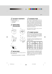
E-1
FEDERAL COMMUNICATIONS
COMMISSION (FCC) WARNING
Instruction to Users
This equipment has been tested and found to comply
with the limits for a Class B digital device, pursuant
to part 15 of the FCC rules. These limits are designed
to provide reasonable protection against harmful interference in a residential installation. This equipment
generates, uses and can radiate radio frequency energy
and, if not installed and used in accordance with the
instructions, may cause harmful interference to radio
communications. However, there is no guarantee that
interference will not occur in a particular installation.
If this equipment does cause harmful interference to
radio and television reception, which can be
determined by turning the equipment off and on, the
user is encouraged to try to correct the interference
by one or more of the following measures.
-
-
Reorient or relocate the receiving antenna.
Increase the separation between the equipment
and the receiver.
Connect the equipment into an outlet on a circuit different from that to which the receiver is
connected.
Consult the dealer or an experienced radio/ TV
technician for help.
This equipment has been certified to comply with the
limits for a Class B computing device, pursuant to
part 15 of the FCC rules. Only peripherals (computer
input / output devices, terminals, printers etc.) certified
to comply to the Class B limits may be attached to
this computer. Operation with non-certified
peripherals is likely to result in interference to radio
and TV reception.
Remarks
To meet FCC requirement, shielded cables are required
to connect the device to a personal computer or other
Class B certified device.
Information to Users
Any change or modifications expressly approved by
the party responsible for compliance could void the
user's authority to operate this equipment.
DOC NOTICE
This product conforms to Canadian Class B emissions
regulations.
Ce produit est conforme aux réglements d’émission
Canadienne class B.
TCO95 N OTICE
This product is delivered with a shielded cord set. In
order to comply with TCOs requirements for low
electromagnetic emission this cord set must be used,
connected to a grounded outlet. If the cord set is
replaced by another cord set we can not guarantee that
the product still complies with TCOs requirements.
E-2
INTRODUCTION
This microprocessor-based, digital control 17” color
monitor is a high performance and easy to use product.
It employs the latest on-screen-menu technology. The
microprocessor capability offers 14 most commonly
used VESA timing modes preset in the factory, and 8
modes for user to adjust to the special timings that
user might have.
We hope that you will find this manual is helpful in
obtaining the fullest use of your monitor, and in
ensuring your personal safety during operation.
POWER SAVING
The monitor will be driven to different power saving
states upon receiving control signals from the
display controller, this meets the EPA (
Environment Protection Agency) Energy Star
requirements and reduces power consumption.
The monitor will work in the following 4 states
according to the VESA standard Display Power
Management Signal:
St a t e
Powe r
Cons umpt ion
LED
Light
ON
Normal
Green
STANDBY
<15W
Yellow
SUSPEND
<15W
Yellow
O FF
< 8W
Amber
The power saving states will be kept until a control
signal has been detected or the keyboard or mouse is
activated. The recovery time from STANDBY/
SUSPEND state to ON state shall be within 3 seconds.
It will take about less than 15 seconds from OFF state
back to ON state.
E-3
INSTALL THE
MONITOR
•
•
•
To connect the tilt/swivel base to the monitor, align
hooks with the sockets on bottom side of the
monitor, and gently push the base towards the front
of the monitor.
The 15-pin D-shell signal connector on the signal
cable will connect easily to the video adapter
output on your personal computer. Lock both
screws on the connector to ensure a firm
connection.
Turn the PC power switch ON. Then turn the
monitor power switch ON, by pressing the switch
inward. The green power indicator will light up.
•
Allow about 30 seconds for the CRT tube to warm
up. Data will be displayed on the screen.
•
If your display fails to function properly, please
first refer to the section "Troubleshooting" in this
manual.
POWER CORD
•
Check first to make sure that the power cord you
use is the correct type required for your area.
•
This monitor has a universal power supply that
allows operation in either 100/120V AC or 220/
240V AC voltage area. No user-adjustment is required.
•
First connect the power cord into your monitor’s
power input socket, and then plug the other end
into a 3-pin AC outlet. The power cord may be
connected to either a wall socket or the power output socket on your PC, depending on the type of
power cord supplied with your monitor.
•
For units to be used at 120V AC:
Use a UL Listed Cord Set consisting of a min.
No. 18 AWG, Type SVT or SJT three-conductor
a maximum of 15 ft. in length and a parallel blade,
grounding type attachment plug rated 10A, 125V.
•
For units to be used at 240V AC (domestic use):
Use a UL Listed Cord Set consisting of a min. No.
18 AWG, Type SVT or SJT three-conductor cord
a maximum of 15 ft. in length and a tandem blade,
grounding type attachment plug rated 10A, 250V.
•
For units to be used at 220/240V AC (outside of
U.S.):
Use a Cord Set consisting of a min. No.18 AWG
cord and grounding type attachment plug rated
15A, 250V. The cord set should have the appropriate safety approvals for the country in which
the equipment will be installed and marked HAR.
E-4
USER CONTROLS AND INDICATORS
a
b
a. Displays menu & exits menu
b. Scrolls through menu to choose an icon
for adjustment /
Adjusts level of selected icon
c. Confirms menu selection
c
1
1.
2.
2
Power LED
Power ON/OFF switch
E-5
USING THE ON-SCREEN MENU
1) Menu screen-press the 1 button to display the menu below and exit menus
Select mark
Press the
button to move the selection
mark to the desired location.
Adjustment icons
1:
CONTRAST
The item presently
being adjusted is
shown.
When the 2 button is pressed.
The selected adjustment screen appears.
:2
CONTRAST
V.SIZE
ROTATION
DEGAUSS
BRIGHTNESS
V.POSITION
COLOR
RECALL
1:
H.SIZE
V.PINCUSHION
LANGUAGE
H.MOIRE
H.POSITION
TRAPEZOID
DISP.FREQ.
V.MOIRE
CONTRAST
:2
2) Adjustment screen (example: horizontal position adjustment)
Name of adjustment screen
Adjustment icon
H.P OS ITIO N
50
1 :
End Button
When the 1 button is pressed,
the adjustment level is stored,
the adjustment screen is ended
and the menu screen returns.
/
The adjustment level is shown by both a number
and a bar. It can be varied with the front
buttons.
: 2
When the 2 button is pressed, the horizontal
size adjustment screen appears.
On the adjustment screen where these two adjustment
icons appear, it is possible to switch between the two
screens by pressing the 2 button.
NOTE: The amount of adjustment depends upon how long you depress the adjustment button. You may have to
tap the button to obtain the desired results.
E-6
INDIVIDUAL
ADJUSTMENT
CONTRAST adjustment
Adjust the screen contrast to match your
personal perference.
Press the
button to decrease contrast and
press the button to increase it.
Direct operation: You can access the
CONTRAST adjustment
screen by pressing the
or
before entering the menu
screen.
Press the 2 key toggles between CONTRAST
and BRIGHTNESS.
BRIGHTNESS adjustment
Adjusts the brightness to get the desired
background level.
Press the
button to make the background
lighter, the button to make it darker.
Press the 2 key toggles between CONTRAST
and BRIGHTNESS.
HORIZONTAL SIZE adjustment
Fills the viewable area horizontally.
Press the button to make the image narrower,
or press the button to make it wider.
Press the 2
key toggles between
HORIZONTAL SIZE and HORIZONTAL
POSITION.
HORIZONTAL POSITION adjustment
Shifts the image on the screen horizontally.
Press the button to move the screen image to
the left, or press the button to move it to the
right.
2
Press the
key toggles between
HORIZONTAL SIZE and HORIZONTAL
POSITION.
VERTICAL SIZE adjustment
Fills the viewable area vertically.
Press the button to make the image smaller,
or press the
button to make it larger. Press
the 2 key toggles between VERTICAL SIZE
and VERTICAL POSITION.
VERTICAL POSITION adjustment
Shifts the image on the screen vertically.
Press the
button to move it downward, or
press the button to move it upward.
Press the 2 key toggles between VERTICAL
SIZE and VERTICAL POSITION
VERTICAL PINCUSHION adjustment
The image can be corrected for barrel
distortion.
Press the button or the button to eliminate
curved vertical lines.
Press the 2 key toggles between VERTICAL
PINCUSHION and TRAPEZOIDAL
correction.
TRAPEZOID adjustment
The image can be corrected for the trapezoidal
distortion.
Press the
button to narrow the top edge, or
press the button to make the top edge wider.
Press the 2 key toggles between VERTICAL
PINCUSHION and TRAPEZOID correction.
ROTATION adjustment
The image can be corrected for tilt picture.
Press the button to tilt the image to the left,
or press the
button to tilt the image to the
right.
E-7
COLOR selection
MANUAL DEGAUSSING
The white in the image can be adjusted.
1) Use the
button to select: (1)9300 OK,
(2)6550O K or (3)the user’s preferred color.
2) If the (3):the user’s color is selected, “2”
appears in the lower right of the On-Screen
Menu.
Press the front 2 button to display the USER
COLOR adjustment screen.
After moving the selector to the degauss icon,
press the 2 button. The degaussing action
takes place a few seconds later.
Note: A sharp snap noise may be heard when
degaussing occurs. This is normal.
USER COLOR
The white in the video image can be adjusted
to the user’s preferred color.
1) Use the 2 button to select R (red) or B
(blue).
2) Use the
button to adjust the color as
desired.
*The GREEN color is fixed and cannot be
adjusted.
IMPORTANT-Memory recall of the user’s
color is not possible, so take note of the initial
setting before adjusting.
When the monitor is turned OFF, user color
keeps the last adjustment.
LANGUAGE selection
The language of the On-Screen Menu can be
selected among English, French, German,
Italian and Spanish. Select with the
buttons.
DISP. FREQ (Input frequency display)
This displays the input synchronization signal
frequency.
It identifies the horizontal and vertical
frequency sent to the monitor from the video
card currently in use.
MEMORY RECALL
It is possible to restore adjustments to the
original factory settings. If the monitor is
operating in a user defined mode, this control
has no effect.
HORIZONTAL MOIRE
Reduce the dark wavy line Moire pattern on
the screen.
Press the
or
button to minimize the
horizontal moire image on the screen.
VERTICAL MOIRE
Reduce the dark wavy line Moire pattern on
the screen.
Press the
or
button to minimize the
vertical moire image on the screen.
E-8
TROUBLESHOOTING
If your monitor fails to operate functionally, it may
be possible to correct the problem by making simple
checks as follows:
Problem
Blank screen
(* note.)
SERVICING
•
Refer all servicing to qualified service personnel.
Serious shock hazards exist within the covers
of this monitor.
Do not open the covers under any
circumstances- there are no serviceable parts
inside.
Check & Adjust
Monitor power switch,
power cord, signal cable,
or connector
PC power switch
Brightness & contrast
controls
Display position
off- center
Vertical centering &
horizontal phase controls
Display too small
or too large
Vertical & horizontal size
controls
Display too bright
or too dim
Brightness & contrast
controls
Refer to the operation instructions for your computer/
video adapter to ensure that you have the correct signal
output source for the monitor. Ensure that the switches
on the video adapter are set correctly for operation
with this monitor.
SIGNAL CONNECTOR
INFORMATION
5
1
15
Pin
Funct ion
Pin
9
Funct ion
If the above steps fail to correct the problem contact
your dealer for servicing by qualified service
personnel.
1
Red signal
2
Green signal 10
Digital ground
3
Blue signal
11
Ground
Please remember that the monitor should be returned
for servicing together with the power cord.
4
Ground
12
SDA (DDC1/DDC2B)
5
*
13
Horizontal
Synchronization
6
Red return
14
Vertical synchronization
& VCLK (DDC1)
15
SCL (DDC 2B)
* Note: You can easily distinguish the problem is on
the monitor or on the computer by using the
monitor’s built-in selftest function.
With the monitor power ON, disconnect the
signal cable from monitor. If you see a “NO
SIGNAL” image on the screen, (shown
below) the monitor is function properly, and
the problem is at PC side, or signal cable.
NO SIGNAL
7
8
*Note:
Green
return
Blue return
NC
This pin is used for self test detection; at
PC side, this pin has to be connected to
ground.
E-9
TECHNICAL SPECIFICATIONS
S c r e e n S i ze
1 7 " vis ua l d ia go na l
Vie w a b le s c r e e n s ize
15.8"
A nt i- G la r e C o a t ing * *
P o we r I n p u t
Vo l t a g e
Fre que ncy
D ot Pit ch
0 . 2 7 mm
Current
R a t ing
2.0 A
D is pla y Ar e a
(H x W)
2 2 5 x 3 0 0 ( mm) , t yp ic a l
P o we r
Cons umpt ion
120 W (MAX.)
D is pla y Color s
I nfinit e
D ime ns ion
(W x H x D)
4 11 X 4 1 4 X 4 2 0
( mm)
M ax.
R e s olut ion
1 2 8 0 D o t s x 1 0 2 4 L ine s
We i g h t
16.5kg
Compa t ibilit y
A ll gr a p hic mo d e s w it h
ho r izo nt a l fr e q ue nc ie s
between 30 K Hz to 69
K Hz
O pe r a t ing
Te mp e r a t u r e
5 C to 35 C
Storage
Te mp e r a t u r e
0 C to 65 C
100 to 240V AC
50 - 60 Hz
S y n c h r o n i za t i o n
H o r i zo n t a l :
Ve r t i c a l :
30 to 69 K Hz
55 to 120Hz
B a n d wi d t h
86 MHz
H umidit y
20% to 80%
( no n- c o nd e ns ing)
I nput Signa l
Vid e o R G B A n a lo g
S ync . TTL S e p a r a te
Alt it ude
U p t o 7 0 0 0 ft
Signa l Ca ble
1 5 - p in D - s ub c o nne c t o r
M PR II /
TCO
M P R 1 9 9 0 :1 0 ,
T C O O p t io na l
* Specifications are subject to change without notice.
** TCO version has a different surface treatment.
E-10
PRESET MODES
M ode
R e s olut ion
(H x V)
H . F r e q.
(K H z)
V. Fr e q.
(H z)
M ode
R e s olut ion
(H x V)
H . F r e q.
(K H z)
V. Fr e q.
(H z)
1
720 x 400
31.4
70
8
1024 x 768
48.3
60
2
640 x 480
3 1. 4
60
9
800 x 600
53.6
85
3
640 x 480
35.0
66
10
1024 x 768
56.4
70
4
800 x 600
37.8
60
11
1024 x 768
60.0
75
5
640 x 480
37.5
75
12
1280 x 1024
64.3
60
6
640 x 480
43.3
85
13
1024 x 768
68.6
85
7
800 x 600
46.8
75