1
INSTALLATION AND OPERATION MANUAL
EPA Certified
Wood-Burning
Fireplace Inserts
Save These Instructions
For Future Reference
Elite™ E260
P/N 775210M, Rev. D 12/2011
Legacy™ C260
Wood Fireplace Inserts
Legacy™/Elite™ Models C/E260
A French manual is available upon request. Order P/N 775210CF.
Ce manuel d’installation est disponible en francais, simplement en faire la demande. Numéro de
la pièce 775210CF.
US
This appliance must be properly installed and operated in order to prevent the
possibility of a house fire. Please read this entire installation and operation
manual before installing and using your wood fireplace insert. Failure
to follow these instructions could result in property damage, bodily
Portland
injury or even death. Contact your local building or fire officials
to obtain a permit and information on any installation requirements and inspection requirements in your area.
Report #050-S-02b-2
WARNINGS
• Hot! Do not touch! The glass and surfaces of this appliance will
be hot during operation and will retain heat for a while after
shutting off the appliance. Severe burns may result.
• Carefully supervise children in the same room as appliance.
CONGRATULATIONS!
Chimney Requirements................................................................... 9
Installation Procedures - Masonry Chimney................................... 9
When you purchased your new wood-burning fireplace insert,
you joined the ranks of thousands of individuals whose answer
to their home heating needs reflects their concern for aesthetics, efficiency and our environment. We extend our continued
support to help you achieve the maximum benefit and enjoyment
available from your new wood-burning fireplace insert.
Positive Flue Connection............................................................... 10
Fireplace Pre-Installation Preparation........................................... 11
Insert Pre-Installation Preparation................................................ 11
Chimney Liner Installation............................................................ 11
Installing the Insert....................................................................... 11
Post Installation Checks................................................................ 11
Thank you for selecting a Lennox Hearth Products wood-burning
fireplace insert as the answer to your home heating needs.
Operating Hints............................................................................. 12
Starting and Maintaining a Fire..................................................... 12
Blower Operation (optional kit)..................................................... 13
TABLE OF CONTENTS
Using This Manual.......................................................................... 2
Important Safety Information.......................................................... 3
Testing Information......................................................................... 4
Draft Requirements......................................................................... 4
Selecting the Proper Venting System.............................................. 4
Negative Pressure Warning . .......................................................... 5
Creosote.......................................................................................... 5
Ash Disposal................................................................................... 5
Fuel
. .......................................................................................... 5
Burn-In Period................................................................................ 5
Operating Techniques and Hints................................................... 14
Getting the Most Out of Your Fireplace insert............................... 14
Maximizing Your Fireplace Insert’s Overall Efficiency.................... 14
Achieving Clean, Long Burns........................................................ 14
Maintenance.................................................................................. 15
Clean Glass................................................................................... 15
Troubleshooting............................................................................ 16
Do’s and Don’t.............................................................................. 17
Replacement Parts Lists..........................................................18-21
Accessories..............................................................................22-23
Safety / Listing Labels................................................................... 24
Product Reference Information..................................................... 26
Paint Curing.................................................................................... 5
Brick Installation............................................................................. 6
Required Clearances....................................................................... 7
USING THIS MANUAL
Hearth Protection............................................................................ 8
Please read and carefully follow all of the instructions found in
this manual. Please pay special attention to the safety instructions
provided in this manual.
PRODUCT IS SUBJECT TO CHANGE WITHOUT NOTICE
2
IMPORTANT SAFETY AND WARNIING
INFORMATION
read THIS MANUAL IN ITS ENTIRETY and understand these Rules to follow for safety.
1.
When this room heater is not properly installed, a house fire
may result. To reduce the risk of fire, follow the installation
instructions. Contact local building or fire officials about
restrictions and installation inspection requirements in your
area.
2. Wear gloves during installation to avoid injury from sharp
edges on the insert and/or its parts.
3. This unit is designed and engineered to burn only dry, wellseasoned wood. Burning wet wood will greatly reduce your
inserts efficiency, produce excessive amounts of smoke and
can cause dangerous chimney fires due to creosote buildup.
4. Before opening the door, the draft control must be fully open
to avoid possible combustion flash (ignition of hot volatile
gases as the door is opened).
5. Never use gasoline, gasoline-type lantern fuel, kerosene,
charcoal lighter fluid, or similar liquids to start or ’freshenup’
a fire in this heater. Keep all such liquids well away from the
heater while it is in use. DO NOT USE CHEMICALS OR FLUIDS
TO START THE FIRE.
6. While burning, fuel utilizes oxygen from the air in the room. Be
sure to allow an adequate amount of fresh air into the room
where the insert is burning.
7. The outside surface of the insert will be hot while burning
properly and can set items like clothing and curtains on fire.
Keep furnishings and other combustible materials away from
the insert. Using the heat from the insert to dry wet clothing
can be hazardous if clothes are placed too near the surface
of the insert.
8. HOT WHILE IN OPERATION. KEEP CHILDREN, CLOTHING
FURNISHINGS AND COMBUSTIBLE MATERIAL A CONSIDERABLE DISTANCE AWAY. CONTACT MAY CAUSE SKIN BURNS.
Do not allow children to play near the insert without close
supervision. Do not touch the insert while it is burning. Use
extreme caution while the unit is in use. Surface temperatures
become dangerously hot and can cause serious burns.
9. Do not allow anyone to operate the insert who is not familiar
with the operating instructions.
10. Attempts to achieve heat output rates that exceed insert design
specifications can result in permanent damage to the insert.
Never leave your insert unattended on high burn rates. This
may cause overfiring. Overfiring the insert may cause a house
fire. If the insert glows, you are overfiring.
11. Keep a water hose or hand-operated fire extinguisher close
for safety.
12. Smoke Detectors - Since there are always several potential
sources of fire in any home, we recommend installing smoke
detectors. If possible, install the smoke detector in a hallway
adjacent to the room (to reduce the possibility of occasional
false activation from the heat produced by the insert). If your
local code requires a smoke detector be installed within the
same room, you must follow the requirements of your local
code. Check with your local building department for requirements in your area.
13. Inspect your chimney at least once a month during the burning season to check for soot and creosote accumulations.
Any accumulations over 1/8” thick should be removed by a
professional chimney sweep. Do not attempt to burn out heavy
creosote accumulations with a hot fire. If large accumulations
are occurring, review your burning procedures.
14. If a creosote fire should develop, the fire department should
be called immediately and then attempts should be made to
control the fire until assistance arrives. If a “runaway” fire
should develop causing over-heating of the insert, the door
and draft regulators should be closed immediately. The fire
should die down once deprived of oxygen. After a severe
chimney fire, the complete chimney system should be checked
before further use.
15. Do Not Use Grate Or Elevate Fire - Build Wood Fire Directly
On Hearth (firebrick). Do not use andirons or other methods
of supporting the fuel.
16. Please read this entire manual before you install and use your
new room heater. Failure to follow instructions may result in
property damage, bodily injury, or even death.
17. Check all local building and safety codes before installation.
The installation instructions and appropriate code requirements must be followed exactly and without compromise.
In the absence of local codes the following standards and
codes must be followed.
18. In the U.S.A, install in accordance with the National Fire
Protection Association’s Code, NFPA 211, Standards for
Chimneys, Fireplaces, Vents and Solid-Fuel-Burning Appliances, or similar regulations, may apply to the installation of
a Solid-Fuel-Burning appliance in your area. In Canada, the
guideline is established by the CSA Standard, CAN/CSA-B365M93, Installation Code for Solid-Fuel-Burning Appliances and
Equipment.
19. DO NOT CONNECT TO OR USE IN CONJUNCTION WITH ANY
AIR DISTRIBUTION DUCTWORK UNLESS SPECIFICALLY
APPROVED FOR SUCH INSTALLATIONS.
20. WARNING: BURNING IMPROPER FUEL (I.E. CHARCOAL)
CAN RESULT IN CARBON MONOXIDE POISONING, WHICH
MAY LEAD TO DEATH!
21. Carbon Monoxide Poisoning – early signs of carbon monoxide poisoning resemble the flu with headaches, dizziness, or
nausea. If you have these signs, get fresh air at once! Have
the heater inspected by a qualified service technician. Some
people are more affected by carbon monoxide than others.
These include pregnant women, people with heart or lung
disease or anemia, those under the influence of alcohol, and
those at high altitudes.
22. Failure to use manufacturer provided parts, variations in
techniques and construction materials or practices other than
those described in this manual may create a fire hazard and
void the limited warranty.
23. Do not make any make-shift compromises during installation.
Any modification or alteration may result in damage to the
appliance or dwelling and will void the warranty, certification
and listings of this unit.
24. These appliances are designed as supplemental heaters.
Therefore, it is advisable to have an alternate heat source
when installed in a dwelling.
25. Do Not Overfire – If Heater or Chimney Connector Glows,
You Are Overfiring.
26. DO NOT CONNECT THIS UNIT TO A CHIMNEY FLUE SERVING
ANOTHER APPLIANCE.
27. DO NOT BURN GARBAGE OR FLAMMABLE FLUIDS SUCH
AS GASOLINE, NAPHTHA OR ENGINE OIL.
3
Testing Information
This manual describes the installation and operation of these non-catalytic
wood heaters. These heaters meet the U.S. Environmental Protection
Agency’s emissions limits for wood heaters sold on or after July 1, 1990.
This heater has been developed, tested and constructed in accordance
with the requirements of UL 1482, ULC S628 and HUD standards and
is listed by OMNI Test Laboratories, Portland, OR. It has been approved
for residential and alcove installations.
Draft Requirements
Your wood fireplace insert is dependent upon a properly functioning
chimney for optimum performance. It is a high efficiency appliance that
loses much less heat up the chimney than older appliances and fireplaces.
For this reason it is important to match the fireplace insert to the chimney.
The chimney has two functions:
1. It draws combustion air into the appliance (without air, no fuel will
burn) and
2. It exhausts combustion by-products. Your new appliance is what is
known as a “natural draft” appliance.
The appliance depends solely on the natural draft of the chimney system
to draw combustion air into the unit. Draft is the force that moves air from
the appliance up into the chimney. The amount of draft in your chimney
depends on the length of the chimney, local geography, nearby obstructions
and other factors. Too much draft may cause excessive temperatures in the
appliance (overfiring). Slow or inadequate draft equals poor combustion
and possible smoking problems. The following are some conditions that
may contribute to poor chimney draft:
1. A chimney too large for your appliance.
2. A chimney with not enough height to produce adequate draft.
3. A chimney with excessive height (this may allow exhaust to cool too
much before exiting, which will stall the rate the exhaust exits).
4. Offsets in the venting system are too restrictive (see Chimney Guidelines).
Inadequate draft will cause the appliance to leak smoke into the room
through the fireplace insert and the chimney connector joints.
performance problems as well as be a safety hazard. A draft test should
read greater than .04’ W.C. (inches water column) and less than .08”
W.C. As per NFPA-211 standard (see paragraph below), the installer
must take into account all variables within the installation and install the
appliance in such a manner that satisfies the draft requirements of the
appliance. See Chimney Guidelines below to assist you in selecting the
proper venting system for your installation.
American National Standards Institute ANSI/NFPA 211, Standard for
Chimneys, Fireplaces, Vents, and Solid Fuel-Burning Appliances
- See Draft Section: A chimney or vent shall be so designed and constructed to develop a flow sufficient to completely remove all flue and
vent gases to the outside atmosphere. The venting system shall satisfy
the draft requirements of the connected appliance in accordance with
the manufacturer’s instructions.
Chimney Guidelines:
• This appliance requires approximately 12 feet minimum of “effective
draw” provided by the venting system. As a rule of thumb, every 90
degree total direction change in the venting will result in a loss of
approximately 5 feet of “effective draw.” Example: If two 45 degree
offsets are used, subtract 5 feet from the actual vertical vent height
to determine your “effective draw.” In this case if you had 14 feet of
vertical vent, the effective draw would only be approximately 9 feet
(14 ft. - 5 ft. = 9 ft.), therefore it may be necessary to add additional
height to the venting system.
• If the venting system is all vertical and the total vent length above the
flue outlet exceeds 14 feet, it is recommended that the 8” to 6” pipe
reducer is used (cat. no. 71134) and a 6” venting system be installed.
At higher elevations, this may not be necessary.
• In well insulated and weather tight homes, it may be difficult to establish
a good draft up your chimney. The poor draft is caused by a shortage
of air in the house (see Negative Pressure Warning on Page 5).
Chimney Height Requirements
The chimney must extend 3’ (.92m) above the level of roof penetration
and a minimum of 2’ (.61m) higher than any roof surface within 10’
(3m) (see below). Check with your local building officials for additional
requirements for your area.
Excessive draft may cause an uncontrollable burn or a glowing red
fireplace insert or chimney part.
Overfiring Damage - If the heater or chimney connector glows, you are
overfiring. Other symptoms may include: Cracking, warping or burning
out of components, plated accessories may turn color, stove glass may
develop a haze, which will not come off with cleaning.
Less than
10' (3 m)
2’ (610 mm) Min.
3' (914 mm)
Min.
Overfiring of a stove or fireplace insert is a condition where excessive
temperatures are reached, beyond the design capabilities of the appliance. The damage that occurs from overfiring is not covered under the
manufacturer’s limited warranty.
3'
(914 mm)
Min.
Figure 1 - Chimney Height Requirements
Also see Troubleshooting on Page 16.
Selecting the Proper Venting System
The appliance is merely one component of a larger system. The other
equally important component is the venting system. This is necessary for
achieving the required flow of combustion air to the fire chamber and for
safely removing unwanted combustion by-products from the appliance.
If the venting system’s design does not promote these ends, the system
may not function properly. Poorly functioning venting systems may create
4
10'
(3 m)
To pass inspection in nearly any jurisdiction, the chimney must meet both
safety and exhaust flow requirements. The (3’ by) 2’ by 10’ rule applies
to both masonry and factory-built chimneys.
* Ref. USA - National Standard, NFPA 211-latest edition and Canada
National Standard CSA B365-01-latest edition. Vents installed with a
listed cap shall terminate in accordance with the terms of the cap’s
listings.
NOTE: DIAGRAMS & ILLUSTRATIONS ARE NOT TO SCALE.
Negative Pressure Warning
Fuel
This appliance is not designed to be operated in a negative pressure.
In very airtight homes with large kitchen exhaust fans, furnace cold air
returns, fresh air exchange systems and any other air system in close
proximity to the heating appliance may create a negative pressure in the
same room as the heating appliance. This can create dangerous back
drafting of the fireplace insert and chimney joints, drawing combustion
by-products into the home. Be sure your home has adequate makeup air
to eliminate negative pressures caused by the above-mentioned sources.
Lennox Hearth Products accepts no liability for damages resulting from
negative pressures described above.
This appliance is designed and engineered to burn, dry, well-seasoned
wood only.
Ventilation Requirements - Provide adequate air for combustion. The
fresh air requirements of this appliance must be met within the space
where it will be installed. Ventilation is essential when using a Solid-FuelBurning heater. In well insulated and weather tight homes, it may be
difficult to establish a good draft up the chimney (caused by a shortage
of air in the home). The lack of air is caused by many common household
appliances which exhaust air from the home (such as a furnace, heat
pump, air conditioner, clothes dryer, exhaust fans, fireplaces, and other
fuel burning appliances). Also, the combustion process of this heater
uses oxygen from inside the dwelling. If the available fresh air delivery
in the dwelling is insufficient to support the demands of these appliances,
problems can result (i.e. excessive negative pressure can develop in the
dwelling which will affect the rate at which this appliance can draft thus
resulting in performance problems. To correct this problem it may help
to open a window (preferably on the windward side of the house).
fireplace insert will not operate at the level that it is meant to unless you
use seasoned, dry wood. Do not burn driftwood or wood that has been
in salt water, doing so will void your warranty. Do not burn treated wood,
coal, garbage, cardboard, solvents, or colored paper. Burning treated
wood, garbage, solvents, or colored paper may result in the release of
toxic fumes. This type of burning will also void your warranty.
Creosote, Formation and Need for Removal
When wood is burned slowly, it produces tar and other organic vapors,
which combine with expelled moisture to form creosote. The creosote
vapors condense in the relatively cool chimney flue of a slow-burning
fire. As a result, creosote residue accumulates on the flue lining. When
ignited, this creosote makes an extremely hot fire. The chimney and
chimney connector should be inspected at least once monthly during
the heating season to determine if a creosote buildup has occurred. If
creosote has accumulated (1/8” [3mm] or more), it should be removed
to reduce the risk of a chimney fire.
Establish a routine for the fuel, wood burner and firing technique.
Check daily for creosote build-up until experience shows how often
you need to clean to be safe. Be aware that the hotter the fire the
less creosote is deposited, and weekly cleaning may be necessary
in mild weather even though monthly cleaning may be enough in
the coldest months. Contact your local municipal or provincial fire
authority for information on how to handle a chimney fire. Have a
clearly understood plan to handle a chimney fire.
DISPOSAL OF ASHES
Ashes should be scooped out of a cool fireplace insert with a small metal
shovel. Ashes should be placed in a metal container with a tight fitting lid.
The closed container of ashes should be placed on a non-combustible
floor or on the ground, well away from all combustible materials, pending
final disposal. If the ashes are disposed of by burial in soil or otherwise
locally dispersed, they should be retained in the closed container until
all the cinders have thoroughly cooled. Ashes can ignite up to 72 hours
after removal from the fireplace insert.
Dry, seasoned wood is that which has been cut, split and allowed to dry
under a covered area where air is free to flow and circulate under and
around the wood (not under a tarp or plastic). Make sure wood is not
stacked directly on the ground, it may absorb moisture from the ground.
It should be allowed to dry in these conditions for a minimum of six
months, preferably one year or more. IT MUST BE UNDERSTOOD
THAT WOOD CANNOT BE LEFT IN ANY KIND OF WET OR DAMP
AREA OR IT WILL NEVER BECOME COMPLETELY SEASONED. Your
Do Not store fuel within space heater installation clearances or within
the space required for refueling and ash removal.
Paint Curing
If your appliance has plated accessories, be sure to clean it with a
household type glass cleaner and a very soft cloth to remove any
fingerprints and residues prior to the first fire and before any fire if
the gold has been handled or soiled. Do not close the door tightly
during the “Burn-In Period.” Also, open the door frequently (every
5-10 minutes) to keep the gasket from adhering to the curing paint.
Ventilate the house well during these first firings as the paint gives off
carbon dioxide and unpleasant odors. It is recommended that persons
sensitive to an imbalance in the indoor air quality avoid the fireplace
insert during the curing process.
Your new appliance is painted with a high temperature paint that cures
during the first few firings. We recommend that you put your fireplace
insert through a regimen of three burns. The first two should last for 20
minutes each at 250 degrees (the fireplace insert should be allowed to
cool completely between each burn). The third should be a burn of at least
450 degrees F. for 45-60 minutes. The paint will become soft, gummy
and emit non-toxic smoke during these burns. After the fireplace insert
cools down for the third time, the paint will harden. DO NOT BUILD A
LARGE ROARING FIRE UNTIL THIS CURING EFFECT IS COMPLETE OR
YOU MAY DAMAGE THE FINISH OF YOUR INSERT. Spray can touchups should be done only with a high temperature stove paint (cat. no.
H8159), available from all Lennox Hearth Products dealers.
Burn-In Period
Please be patient with the heat output of your fireplace insert for the first
few weeks. The steel will go through a curing process that eliminates
moisture, which is deep in the steel and firebrick. This moisture will
reduce initial heat output of your fireplace insert and may make it difficult to start. After you have broken in the paint on the fireplace insert
it will be necessary to build hot fires to thoroughly remove the moisture
from the appliance. Running the fireplace insert with the draft fully open
for 1 to 1-1/2 hours after starting and adding generous amounts of fuel
during the first week or two should complete the curing process. We
recommend the use of a thermometer attached to the fireplace insert top
or chimney. Temperatures on the connector pipe should run in the 250600 degree range. (DO NOT OVERFIRE THE INSERT DURING THIS
PROCESS. IF THE INSERT OR CHIMNEY BECOMES RED, REDUCE
THE AMOUNT OF AIR ENTERING THE INSERT IMMEDIATELY).
5
WARNING: IF THE BRICKS ARE NOT INSTALLED EXACTLY AS
SHOWN THEY COULD FALL OUT OF PLACE DURING REFUELING
OR BURNING OF THE INSERT CAUSING SERIOUS INJURY.
Brick Installation
Brick Installation
CAUTION: Wear gloves during brick installation in case of
sharp edges inside the fireplace insert.
Note: Installation of the baffle boards and baffle blanket is easier when
you can still access the flue outlet, (before connecting the flue vent). Be
sure the baffle blanket is placed flat on the baffle boards so as not to
block exhaust flow to the flue. Use a ruler or a piece of kindling to
reach over the baffle blanket to be sure it is completely flat on top of
the baffle boards.
1. Install bricks #1-28 in the numbered sequence shown in Figure 2.
2. Next, you will install the rear baffle boards which are the smaller two
of the four baffle boards. The boards will be installed with the 5-1/2”
dimension from the front to the rear of the firebox. These boards
will be placed on the top side of the rear baffle just to the rear of the
middle secondary tube, you will push the baffle boards towards the
rear of the firebox until they fall in place at the rear side of the middle
secondary tube. You will place one board to the far left side of the
firebox and one board to far right side of the firebox. Confirm that
both boards are laying flat on the rear baffle and that they are not
overlapping each other.
3. Next, you will install the baffle blanket. It will be installed with the
15-1/2” dimension from the front to rear of the firebox. Install by
lifting it into place between the front and rear baffle. Place the blanket
over the rear baffle and rear baffle boards that you have just installed.
Next you will place the baffle blanket that is protruding beyond the
front side rear baffle on the top side of the front baffle.
4. The final step of the baffle board & baffle blanket installation will be
installing the front baffle boards. The front baffle boards will be the
two remaining baffle boards which are the larger two baffle boards
of the four baffle board kit. They will be installed with the 9-5/8”
dimension from the front to rear of the firebox. Start by setting the
back side of the board on the rear baffle making sure that it is placed
far enough back to lift up and onto the front baffle. Next you will
place the front edge of the front baffle boards on the top side of the
front baffle and slide them towards the firebox front until it stops
against the front baffle edge. You will do this with each front baffle
board with one to the right side of the firebox and one to the left
side of the firebox. Confirm that the baffle blanket is directly on top
of the baffle boards and that it does not protrude beyond the front
baffle or front baffle boards as shown in Figure 4.
Brick Sizes
(see Figures on this page)
A = 4-1/4” x 9”
D = 2-1/8” x 6-1/4”
E - 1-3/4” x 9”
F = 4-1/2” x 9”
G = 2-1/8” x 4-1/4”
H = 4-1/4” x 4-1/2”
S = 2-1/8” x 9”
22-1/2”
Baffle
Insulation
Parts
1” Thickness
Baffle Blanket
11-1/4”
1/2” Thickness
Front Baffle Boards
(2 included)
22
S
1/2” Thickness
Rear Baffle Boards
(2 included)
Figure 3
D
Side Cut-A-Way View of Firebox
14
F
2
F
15
F
19
F
3
A
16
A
20
H
4
F
17
F
Front Baffle
Board
25
S*
5
F
10
F*
18
F
D
8
9 F
E
7
F
1
F
6
F*
24
S
5-1/2”
26
28
23
G
9-5/8”
11-1/4”
Baffle Blanket
S*
29
15-1/2”
11
F
12
F
13
E
Rear Baffle
Board
0.0
0.2
0.4
0.6
0.8
1.0
21
F
Front View
See the following for brick sizes
*Fits against the back of the firebox.
Firebox
Brick
Figure 4
Note: These bricks may be slightly smaller to adjust for steel and
firebrick tolerances beyond our control. Be sure to measure and
mark bricks with their numbers when removing.
6
Figure 2 - Firebrick Diagram
NOTE: DIAGRAMS & ILLUSTRATIONS ARE NOT TO SCALE.
Required Clearances
Maximum Mantel Depth = 9” (229mm)
COMBUSTIBLE MANTEL
WARNING: BE ABSOLUTELY SURE THE DISTANCE BETWEEN
THE HEATER AND THE SURFACE OF ANY COMBUSTIBLE CONSTRUCTION IS NOT LESS THAN SHOWN ON THIS PAGE.
*B
*C
*D
20”
20”
15”
762mm
E260
23”
C260 with mantel
and/or side
shields u
508mm
17”
508mm
20”
15”
8”
200mm
8”
200mm
432mm
17”
14-1/2”
F (1)
G
H
J
M
14”
22-1/2”
5-1/4”
50-1/2”
14”
22-1/2”
5-3/4”
14”
22-1/2”
5-1/4”
368mm
20”
508mm
381mm
E(1)
584mm
432mm
508mm
381mm
8”
200mm
Side Facing Material
*A
30”
SIDE WALL
Model
C260
Top Facing / Trim
8”
A
B
D
Insert
C
200mm
Hearth Protection
Model
C260
E260
C260 with mantel
and/or side
shields u
22”
559mm
22”
559mm
22”
559mm
356mm
356mm
356mm
572mm
572mm
572mm
133mm
133mm
133mm
1283mm
E (Canada)
E (USA)
Figure 5
45”
1143mm
38”
Mantel
965mm
Trim
* Reduced clearances may be available for A, B, C and D dimensions
per NFPA 211 - latest edition, Standard for Chimneys, Fireplaces,
Vents and Solid Fuel-Burning Appliances (in Canada CSA B365 latest edition). See section on “Reduction of Appliance Clearance
with Specified Forms of Protection.”
**
** Side view of optional mantel deflector shown.
F
uElite™ E260 - Not tested for reduction of clearances
(1)Hearth extension reductions: 2” (51 mm) reduction for 2” (51 mm)
raised hearth. (USA) 16” minimum hearth extension on all stoves
and inserts as measured from the door opening of the unit. (Canada)
18”(450 mm) minimum hearth extension on all stoves and inserts
as measured from the door opening of the unit. Minimum distance
of floor protection to the side = 8” (200 mm). This is measured
from the sides of the door opening in the USA and from the sides
of the insert in Canada.
G
6-1/2”
165mm
M
J
8” Ø
Flue Collar
H
Hearth Protection
Figure 6
Notes:
• Facing material that projects more than 3/4” (19mm) from the wall
is considered a mantel or side wall.
C/E260
Masonry Fireplace
UBC Chapter 37
Depth Min.
14-3/4” (375mm)
Height Min. u
22-3/4” (578mm)
Width Min.
30-1/2” (775mm)
Lintel Max. Depth u
5-1/4” (133mm)
u Without use of adjustable offset box or smoke deflector
Table 1 - Fireplace Sizing NOTE: DIAGRAMS & ILLUSTRATIONS ARE NOT TO SCALE.
7
Using the r formula:
Hearth Protection
The hearth and/or floor protection must be a thermally rated noncombustible hearth/floor protector meeting or exceeding a thermal rating
of k=.84 or equivalent with a listed thickness of listed thickness of 3/4"
(19 mm) minimum in the USA and Canada. The covering must extend
USA-16”/Canada-18” (C260) and 22” (E260) in front of the heater and
8” to the side (measured from door opening in the USA and measured
from the side of the unit in Canada).
Using Alternate Material As Floor / Hearth Protection
The hearth extension or alternate material used as a floor/hearth protector must be constructed of a durable noncombustible material having
an equal or better thermal conductivity value (lower k value) of k =.84
BTU/IN FT2 HR °F or a thermal resistance that equals or exceeds r = 1.19
HR °F FT2 IN/BTU with a minimum thickness of 3/4”. With these values,
determine the minimum thickness of the alternate material required using
the formula(s) and shown in Table 2.
Note: Any noncombustible material having a minimum thickness of
3/4”(19 mm) whose k value is less than .84 or whose r value is more
than 1.19 is acceptable. If the alternate material used has a higher k value
or lower r value will require a greater thickness of the material used. In
some cases, if the k value is less or the r value higher, a thinner material
may be used.
Methods of determining floor protection equivalents:
To determine the thickness required for the alternate material when
either the "k" value or "r" value is known, use either the k formula or r
formula.
Example: If Micore 160 Mineral Fiber Board is to be used for the floor
protection, how thick must this material be?
kM = k value per inch of alternate material
rM = r value per inch of alternate material
TM = minimum thickness required for alternate material
TS = standard thickness of the alternate material
k-value (per Inch) of alternate material (kM) x
k-value (per inch) of listed material (kL) Specified min.
thickness
of listed
material (TL)
TM (inches) =
kM
*.84
x
TL
TM (inches) =
*.35
*.84
x
.75"
.312 (inches)=
.417
x
.75"
Answer - The minimum required thickness of the Micore 160 is .312"
therefore round up to nearest standard thickness available which is 3/8”
(.375”)
8
rL
rM
TM (inches) =
.312 (inches)=
Specified min.
thickness
of listed
material
x
TL
*1.19
*2.86
x
.75"
.416
x
.75"
Answer - The minimum required thickness of the Micore 160 is .312"
therefore round up to nearest standard thickness available which is 3/8”
(.375”)
Listed Material
k (per inch)
Listed Material
.84
KL
r (per inch)
1.19
rL
Listed Min. Thickness
3/4" (.75")
TL
** Approved Alternate Materials for Floor/Hearth Protection
Alternative Materials
Thermal Values
k (per inch)
KM
r (per inch)
rM
Minimum Thickness
(rounded to nearest 1/8 inch)
Min. Thickness
TM
Kaowool M Board
.47
2.13
.42" (1/2")
Micore 160™
.35
2.86
.31" (3/8")
Micore 300™
.46
2.17
.41" (1/2")
Durock™ Cement Board
1.92
.52
1.71" (1-3/4")
Hardibacker™
1.95
.51
1.74" (1-3/4")
Hardibacker 500™
2.30
.43
2.05" (2-1/8")
Cultured Stone Hearthstone™
2.82
.35
2.52" (2-5/8")
Wonderboard
3.23
.31
2.88" (3")
Super Firetemp M
.61
1.64
.54" (5/8")
Super Firetemp L
.54
1.85
.48" (1/2")
Face brick
9.00
.111
8.04" (8-1/8")
Common brick
5.00
.20
4.46” (4-1/2")
U.S. Gypsum
U.S. Gypsum
U.S. Gypsum
Johns-Manville
Note: An asterisk "*" indicates, it is a value taken from Table 2.
Using the k formula:
r-value (per Inch) of listed material
x
r-value (per inch) of alternate material TM (inches) =
Johns-Manville
kL = k value per inch of listed material
rL = r value per inch of listed material
TL = minimum thickness of listed material
Minimum thickness of
=
alternate material (TM) Minimum thickness of
=
alternate material Cement mortar
5.00
.20
4.46” (4-1/2")
Ceramic tile
12.5
.08
11.16" (11-1/4")
Marble
~11
~.09
9.82" (9-7/8")
Table 2 - USA AND CANADA REQUIREMENTS
** If the hearth extension material(s) that is intended to be used is NOT listed
on Table 2, the material can still be used if the material(s) is noncombustible.
However, the manufacturer of the material must provide either the listed k-value
per inch or r-value per inch with listed thickness so that the minimum thickness
required for the hearth can be calculated (per instructions here or as specified
in the NFI Certification Manuals).
Note: Also see NFI (National Fireplace Institute) Certification Manuals showing other acceptable calculation methods and acceptable alternate materials
which can be used.
Chimney Requirements
This appliance is approved for use in a masonry fireplace built to UBC
Chapter 37 or equivalent with a minimum 30-1/2” (775mm) opening
width at the front of the fireplace.
This appliance may be installed using 6” chimney in vertical installations
utilizing a 8” to 6” reducer (cat. # 71134) at the flue collar. If the venting
system is all vertical and the total vent length above the flue outlet exceeds
14 feet, it is recommended that the 8” to 6” pipe reducer is used and a
6” venting system be installed.
Do not remove brick or mortar from masonry fireplace to accommodate
insert. Approved with or without positive flue connection. Approved
with minimum 6” (152 mm) diameter stainless steel listed reline system.
Country™ Collection inserts are tested to UL 1482 / ULC S628 and listed
by OMNI-Test Laboratories, Inc.; Portland, OR.
IMPORTANT NOTE: See Draft Requirements and Selecting a Proper
Venting System on Page 4 to assist you in choosing the proper venting
system for your installation.
Remove and clean behind unit frequently, as creosote build-up may
occur rapidly.
Warning: Chimney connector must be in good condition and kept clean.
Do not install damaged parts.
Installation Procedures - Masonry Chimney
Notes:
• Although not required, a full-length stainless steel liner is recommended
for optimum safety and performance. See your Lennox Hearth Products
dealer for details.
• When installing your fireplace insert with a positive flue connection
(see Page 10), be sure to leave the insulation off the surround panels
(flanges) and leave a 1/4” (6 mm) airspace insulation off the surround
panels and the facing of your fireplace.
4. Open or remove the existing fireplace damper. Make sure the damper
cannot fall closed.
5. Install the two 1/2” x 3” (13 mm x 76 mm) leveling bolts -heads up- a
few turns in the leveling nuts on each side of the outer chamber of
the insert at the lower rear corners.
6. Position the insert in the center of the fireplace opening and push it
back until the surround brackets are approximately 2” (51 mm) away
from the fireplace front.
7. Install the side surround panels and push the insert up snug against
the fireplace face. Then with the location selected remove the surround
panels and level the fireplace insert with the leveling bolts using a 3/4”
(19 mm) socket, extensions (to reach the bolt head) and a ratchet.
8. Glue the insulation around the outer edge of both the top and side
surround panels.
9. Install the surround panels loosely, align and tighten. Check for a
tight fit against the fireplace.
10. Locate the draft rod extension (5/16” [8 mm] round by 11-3/4” [299
mm] long) and a coupling nut (5/16”/8 mm x 7/8”/22 mm).
11. Slide the extension draft rod through the bracket attached to the
bottom of the left side hearth plate, making sure the end without the
grooves is toward the fireplace insert body. Thread the coupling nut
on the end closest to the fireplace insert body and then thread the
coupling nut on the rod from the fireplace insert.
12. Slide the fireplace insert tight to the fireplace face. Level the insert
with the leveling bolts using a 3/4” socket, extensions (to reach in to
the bolt head) and a ratchet.
13. To install the decorative brass trim on the top surround panel, connect
the 3 pieces at the mitered corners using the corner brackets supplied. Slide the assembled trim down onto the top surround panel.
The surround should fit snugly in the groove towards the back of the
trim.
14. Install the top surround panel on the fireplace insert with the three
screws supplied. Tighten snugly.
15. Install the blower and blower extensions per the instructions provided
in the blower kit.
16. Install the brick and baffle as per instructions on Page 6.
• This appliance may be vented into a code-approved masonry chimney
with flue liner.
1. READ ENTIRE INSTALLATION INSTRUCTIONS.
2. Check all REQUIRED CLEARANCES as specified in the previous section
(Page 7) of this installation and operation manual.
3. Wear gloves during installation in case of sharp edges on the fireplace
insert and it’s parts.
NOTE: DIAGRAMS & ILLUSTRATIONS ARE NOT TO SCALE.
9
POSITIVE FLUE CONNECTION
A full chimney liner
is recommended
A positive flue connection is providing a seal between the vent pipe or
liner and the existing fireplace chimney for the purpose of preventing
room air passage to the chimney cavity of the fireplace. There are different approved methods to achieve this. See Direct Connect Positive Flue
Connection on this page.
When creating a positive flue connection, a positive flue connector ring
kit is required (sold separately - see Figure 7). The connector ring kits
(listed below) provide a means to directly attach rigid pipe or an flex
pipe adaptor to the flue outlet.
Fireplace
Chimney
Must extend starter
section past the damper
area as a minimum
u
71162 - 8" Positive Flue Connector Ring Kit
71163 - 8" to 6" Reducer w/ Positive Flue Connector
Side View
of Insert
Install connector ring kits per instructions provided in kits
Rigid Pipe, Offset Box or
Flex Pipe Adaptor
uA non-combustible seal is required at the damper area (to prevent
dilution air from entering the chimney). See Direct Connect Positive
Flue Connection on this page. A seal-off plate method is shown here.
Figure 8 - Positive Flue Connection
Top of Insert
In Back
Positive Flue
Connector Ring
(sold separately)
}
Cat. No. H6834, 1/4” to 6-1/4” adjustable
Cat. No. H6835, 6” to 13” adjustable
3-3/4”
v
1-1/2”
2-1/8”
C/L
5-1/8”
6”
Figure 7 - Connector Ring Kit
C/L
1-1/2”
w
Direct Connect Positive Flue Connection
H6834 - 17”
H6835 - 22”
Required in Canada
SIDE VIEW
See the following instructions for approved methods of achieving a
positive flue connection - See Figure 8.
A qualified installer should evaluate the existing fireplace to determine
the best method for achieving a positive flue connection between the
vent pipe or liner and the existing fireplace chimney. The most common
method for achieving a positive flue connection in masonry fireplaces
is to secure a seal-off plate (i.e. 22-gage sheet steel) in the fireplace
throat using masonry screws. Other acceptable methods include packing
noncombustible material (i.e. high temp fiberglass or ceramic insulation)
around the vent pipe or using a flue adapter. Whatever “seal off” method
is used, it must effectively seal the area to prevent room air passage to
the chimney cavity of the fireplace.
v
8” Dia.
6” Dia.
14-1/16”
TOP VIEW
Offset Boxes
Offsets can be handled using an offset box (it aligns flue outlet of insert
with the fireplace flue (see Figure 9). Care should be used to ensure
that this adjustable offset box is oriented so it does not angle down when
positioned on the insert flue outlet (level or slightly up at the outbound
end is recommended).
10
w
vTop 6” collar attaches to rigid pipe or flex liner.
wBottom 8” collar attaches to connector ring on insert flue outlet.
Figure 9 - Offset Box Dimensions
NOTE: DIAGRAMS & ILLUSTRATIONS ARE NOT TO SCALE.
Clearance to Combustibles
See “Required Clearances” on Page 7.
Fireplace Pre-Installation Preparation
NOTE: LENNOX HEARTH PRODUCTS RECOMMENDS PROFESSIONAL INSTALLATION BY A LICENSED AND BONDED INSTALLER.
SEE YOUR DEALER FOR RECOMMENDATIONS. IMPROPER
INSTALLATION OR MIS-USE WILL VOID YOUR WARRANTY AND
CREATE A SERIOUS SAFETY HAZARD.
Remove any doors or screen materials from the fireplace opening. Remove the damper mechanism completely. Also remove grates or ember
catches inside the fireplace hearth. If your fireplace is equipped with a
smoke shelf or baffle and if it interferes with the installation it may be
removed. Side and rear refractory may also be removed, if necessary,
to facilitate installation. No modifications shall be done unless allowed
on the previous list. Retain all removed parts, they must be reinstalled
before the fireplace can be used in it’s original condition.
Install the side surround panels with the screws supplied. Push the insert
in until there is approximately a 1/4” (6 mm) gap between the back of the
surround panels and the face of the fireplace. Before installing the top
surround panel, make sure all connections are tight and that no part of
the insert or chimney is touching the firebox or chimney in the fireplace.
There must be a minimum of 1” (25mm) clearance between the fireplace
insert and the zero clearance fireplace. Install the top surround panel.
If additional support is necessary, factory punched holes in the front
corners of the bottom air chamber will accept leveling legs. Carefully
measure the distance from the hearth protection to the bottom of the
fireplace insert. Use 3/8” diameter bolts that are 1/2” (13 mm) longer that
the distance just measured. Thread a nut onto the bolt approximately 1”
(25mm). Lift the fireplace insert slightly and insert a bolt into each hole
and then thread the nut up the bolt until the front is securely supported.
Install another nut onto the bolt through the air space in the fireplace insert
and tighten securely. If desired an insert front support, Cat. No. H5296,
is available to fill the space between the insert and the hearth protection.
Install the brick and baffle as per Page 6.
Insert Pre-Installation Preparation
Install the two 3” (76 mm) long bolts (with the head up) through the nuts
attached to the insert on the lower rear corner of each side. This will allow
you to level the insert when placed into the fireplace.
Measure from the front of the top surround mount to the center of the flue.
Determine if there is an alignment problem in connecting a liner from the
chimney to the insert’s flue. If there is an alignment problem, connection
can be made using a short piece of stainless flex or a stainless steel offset
box (available from your dealer). Before installing the liner, make any
attachment brackets or drill any holes in the liner, offset box, or insert.
Once installed, it may be difficult or impossible to drill additional holes.
Post Installation Checks
1. Check that all chimney pipe joints are securely fastened.
2. Be sure all roof flashings are watertight (if applicable).
FOR YOUR OWN PROTECTION AND INSURANCE PURPOSES,
HAVE YOUR CHIMNEY AND CONNECTOR PIPE INSTALLATION
INSPECTED BY YOUR LOCAL BUILDING CODE AUTHORITY OR
FIRE MARSHAL BEFORE STARTING A FIRE IN YOUR STOVE OR
INSERT. NOTIFY YOUR INSURANCE COMPANY.
Chimney Liner Installation
Remove the existing chimney cap and install a stainless steel liner into
the chimney (if a special section has been used or drilled to attach to the
insert, it must be the bottom piece). The next piece should be a dripless
slip joint; followed by the rest of the chimney liner. Fasten the chimney
at the top when it is positioned so that the slip joint will allow the lowest
piece to slide up enough to clear the insert during installation. Insulate
the top four to six feet between the liner and the chimney to prevent heat
loss. Install the cap and flash if necessary to prevent water or creosote
from entering the chimney’s venting system.
From inside the fireplace firebox, attach any adapters or flue offsets and
slide the liner up as far as necessary for the bottom piece to clear the
insert during installation.
In Canada, This fireplace insert must be installed with a continuous
chimney liner of 6” or 8” diameter extending from the fireplace insert
to the top of the chimney. The chimney liner must conform to the
Class 3 requirements of CAN/ULC-S635, Standard for Lining Systems
for Existing Masonry or Factory-Built Chimneys and Vents, or CAN/
ULCS640, Standard for Lining Systems for New Masonry Chimneys.
FIREPLACE WARNING TAG
The factory built firebox must accept the insert without modification
other than removing bolted or screwed together pieces such as baffles
/ smoke shelf / deflectors, ash lips, glass door, screen or door tracks,
log grates, refractory or masonry lining and damper assemblies. Any
fireplace component, which is removed, must be retained so they can
be reinstalled to restore the fireplace to its original operating condition. The removal of any part must not alter the integrity of the outer
shell of the pre-engineered fireplace cabinet in any way. Any parts
removed must be replaceable. If any components are removed from
(or altered) from the existing fireplace, a metal Warning tag (shown
below) must be affixed inside the fireplace firebox, so that it shall be
visible upon removal of the fireplace insert. Note: Secure the tag using
screws or nails to the fireplace.
WARNING
Installing the Insert
Place the insert into the fireplace, making sure to center it side to side.
Slide the insert in until the surround mounts are approximately 1/2” (13
mm) from the face of the fireplace where the surround panels cover.
Lower the chimney and make attachment to the insert. Level the fireplace
insert by using a 3/4” socket and a long extension and adjusting the bolts
on either side of the insert.
THIS FIREPLACE HAS BEEN ALTERED TO
ACCOMMODATE A FIREPLACE INSERT AND
SHOULD BE INSPECTED BY A QUALIFIED
PERSON PRIOR TO RE-USE AS A
CONVENTIONAL FIREPLACE.
NOTE: DIAGRAMS & ILLUSTRATIONS ARE NOT TO SCALE.
11
Operating Hints
Starting and Maintaining a Fire
1. Burn only dry, well-seasoned wood for maximum heat output. In some
states it is illegal to burn wet wood or anything other than clean, dry
wood products.
2. Your fireplace insert is designed to operate with the door closed!
Operate only with the door shut tightly at all times except when loading wood and possibly on start up to establish a draft. Never leave
the unit unattended while the front door is slightly opened.
3. DO NOT hit or move the baffle boards while loading wood. Occasionally check the baffle. Make sure the baffle blanket is always flush with
the front of the baffle boards. Loading oversized logs may dislodge
the baffle boards.
4. CAUTION: THE DRAFT CONTROL MUST BE FULLY OPEN
BEFORE OPENING THE DOOR TO AVOID POSSIBLE COMBUSTION FLASH!! (Ignition of hot volatile gases as the door is opened).
5. Feeding excessive amounts of fuel to the fireplace insert should be
avoided. It is important to supply it with sufficient draft and fuel to
maintain a moderately hot fire. If, during overnight burns, heavy
creosote deposits develop inside your fireplace insert and on the
door, the draft is set too low - review your burning habits!
CAUTION
Be careful not to abuse door assembly by striking or
slamming it. If the door assembly or glass is broken or
damaged, they must be replaced with factory original
parts before heater can be safely operated. Use only
components provided by the manufacturer as replacement parts.
OK
Be sure to clean plated accessories with a household type
glass cleaner and a very soft cloth to remove any fingerprints
and residues prior to the first fire.
1. NEVER USE FLAMMABLE LIQUIDS TO START OR REKINDLE
A SOLID FUEL FIRE!!
2. Fully open the primary draft control by pulling the 1” plastic knob
out on the left side (lower front corner) until it stops (away from the
fireplace insert). This control determines the amount of air entering
the fireplace insert. Pushing it towards the fireplace insert reduces
the burn rate in the firebox. For your convenience, the rod on this
control is marked with four grooves to assist you in obtaining repeatable burn rates.
3. Place a small amount of crumpled paper in front of the firebox and
cover it with a few pieces of kindling.
4. Light the paper and allow sufficient time for the kindling to become
fully engulfed in flames. You will now close the wood units front door.
(Your wood units front door may or may not need to be left slightly
open during this start up process, this depends on the appliance model
and the amount of draft present. Do not leave the unit unattended
while the front door is slightly open) Once kindling is burning well,
larger pieces of wood may be added, then the door should be fully
closed if there was the need to keep it slightly open during start up.
DO NOT LEAVE THE APPLIANCE UNATTENDED WHILE THE
FRONT DOOR IS SLIGHTLY OPEN.
CAUTION: Do Not alter the adjustment range of the draft
control for increased firing for any reason.
Operate only with fuel door and ash drawer closed. Maintain
all seals in good condition. Do not operate with broken glass.
Do Not build the fire too close to the glass.
Do not operate the appliance with the door open or ajar other
than possibly during start up to create a draft (Do not leave
the unit unattended while the front door is slightly open during start up). Operating the appliance with the door open
other then in initial start up if needed will produce extreme
temperatures within the appliance. Damage caused from
over-firing is not covered under the manufacturers limited
warranty.
Figure 10
12
5. For best results, use smaller pieces of wood to get the insert temperature very high before loading larger wood for sustained burns.
If necessary, crack the door to allow ignition of the fuel charge. Do
not leave the unit unattended while the front door is slightly open.
Now you can add larger pieces of wood and after several minutes of
high burn, set the left control for the desired heat output. Check the
exhaust in about 15 to 20 minutes. Large amounts of smoke indicate
an improper burn setting (either too high or too low). Adjust and
recheck in 5 to 10 minutes.
NOTE: DIAGRAMS & ILLUSTRATIONS ARE NOT TO SCALE.
BLOWER OPERATION
Blower Operation
The blower can be operated manually or automatically (blower will
turn on when the insert is hot and turn off when the insert is cool).
The rocker switch on the control panel allows you to select between
manual operation or automatic operation as follows (see Figure 10):
MANUAL OPERATION: Turn rocker switch to the manual position (up)
and adjust rheostat knob to the desired speed. The blower will have to
be manually turned “OFF” by rotating the rheostat knob counterclockwise until it clicks.
AUTO OPERATION: Turn rocker switch to the “AUTO” position and
the rheostat to the ON position (rotate rheostat knob clockwise until it
clicks). When the insert warms up, the blower will automatically turn
on (adjust rheostat knob to the desired speed setting). When the insert
cools down, the blower will automatically turn off.
Rheostat Operation - The highest blower speed is obtained by turning
the rheostat knob clockwise until it clicks “ON”, then rotate towards
“HIGH” to increase blower speed. Rotate the knob clockwise for a
lower speed. To turn off, continue to rotate the knob counterclockwise
until it clicks “OFF.”
Manual / Auto
Rocker Switch
Blower Speed Control
Knob (rheostat)
Figure 11 - Blower Controls
WARNINGS
The blower must be plugged directly into a properly
grounded three-prong receptacle, 120 VAC, 60 Hz, single
phase. Do not cut or remove the grounding prong from
this plug. Do not route power cord under or in front of
appliance.
Installation must be in accordance with National Electrical Code, ANSI/NFPA 70 - latest edition. In Canada,
the current CSA C22-1 Canadian Electrical Code - latest
edition.
Blower Operation Guidelines
While in auto operation mode, the blower will turn off and on based on
the temperature of the appliance. Auto operation ensures there is sufficient heat build-up to warm the air being moved by the blower before the
DANGER: Disconnect power
blower is turned on. Likewise, when the appliance cools off, the blower
is turned off to prevent circulating cool air. Depending on the size and
intensity of the fire it may be necessary to adjust the blower speed ac-NOTE: SWITCH CONDITIONS
cordingly to ensure un-interrupted blower operation. For example a smallGIVEN AT ROOM TEMPERATURE
fire may require a slower blower speed to keep the heat output by the
TWO POSITION
blower consistent. If the blower is operated in manual mode, it may beN/C = NORMALLY CLOSED
SWITCH
MANUAL/TEMPERATURE
necessary to adjust the blower speed as the fire begins to burn down andN/O = NORMALLY OPEN
the appliance is no longer hot enough to effectively heat the air moved
by the blower. If the air coming from the blower feels cool, one should = FEMALE DISCONNECT
either decrease the blower speed or stoke the fire to build up more heat. = MALE DISCONNECT
= STUD CONNECTION
before servicing blower.
AUTO-RESET
TEMPERATURE
SWITCH N/O
RED
YLW
RED
WHT
NOTE: Turn blower off before opening the door to load the fuel.
BLK
RED
POWER CORD
AUTO
TEMPE
SWITC
GRN
NOTE: SWITCH
CONDITIONS
GIVEN AT ROOM TEMPERATURE
SPEED
CONTROL/OFF
N/C = NORMALLY CLOSED
N/O = NORMALLY OPEN
NOTE: SWITCH CONDITIONS
= FEMALE DISCONNECT
YLW
GIVEN AT ROOM TEMPERATURE
= MALE DISCONNECT
= STUD CONNECTION
ROOM AIR
TWO POSITION BLOWER
SWITCH
MANUAL/TEMPERATURE
TWO P
SWR
MANUAL/T
WHT N/C = NORMALLY CLOSED
N/O = NORMALLY OPEN
BLK
R
Figure 12 - Blower Wiring Schematic
= FEMALE DISCONNECT
NOTE: DIAGRAMS & ILLUSTRATIONS ARE NOT TO SCALE.POWER
= MALE DISCONNECT
CORD
= STUD CONNECTION
GRN
13
WHT
Operating Techniques and Hints
Recent developments in wood-burning technology have made woodburning a cleaner and more convenient way to heat your home. Overall
efficiency in a wood-burning appliance is a combination of combustion
efficiency and heat transfer efficiency. Whether heating your entire
home or just a room or two, your understanding of how to best operate
your stove or insert will enhance its overall efficiency and performance.
What this can mean to you is longer, cleaner burns, less wood use and
more heat.
Getting the Most Out of Your Fireplace insert
The following sections will outline techniques you can use to “get the
most out of your fireplace insert.” Please read them carefully.
Maximizing Your Fireplace insert’s Overall
Efficiency
It is important to know that for high, combustion efficient, clean burns,
you will need to have sufficient temperatures inside the firebox for
thorough combustion. The best method for determining if you have
sufficient temperatures is to watch the brick lining in your firebox. When
you first light your fireplace insert, the bricks will turn a dark brown or
black. After 20 to 30 minutes of a hot fire, most of the bricks should
return to near their original light brown or yellow color. This means the
bricks have reached a high enough temperature for your fireplace insert
to achieve high combustion efficiency.
Second and just as important, is achieving a high level of heat transfer
efficiency. Slowing the rate of flow through the stove or insert enhances
heat transfer, thus allowing more time for heat to be transferred into your
home. To do this, be sure to thoroughly preheat your fireplace insert and
then reduce the amount of primary air by closing the draft control (lower
left) to about 1/2 to 3/4 open. This will decrease the excess oxygen in
your flue, which carries heat up your chimney, but should still be enough
air to allow the fireplace insert to produce its maximum heat output.
(More air may produce a lightly greater amount of heat, but will greatly
increase wood consumption). When the area being heated reaches a
comfortable temperature, slow the burn rate by closing the control to
further improve heat transfer.
To get the most out of your fireplace insert, you will need to combine
good combustion efficiency with good heat transfer practices. The following are some tips on how to operate your fireplace insert to achieve
the highest overall efficiency.
14
1. Thoroughly preheat your fireplace insert before slowing the burn rate
by closing the draft control.
2. Measure the fireplace insert temperature at the hottest point on the
insert top or face. Use this information to repeat burn rates.
3. Once preheated, add wood (if needed) and partially close the draft
control (lower left).
4. Operate your fireplace insert as much as possible in the low to medium
burn ranges.
5. Do not lower the draft setting so low as to completely extinguish
the flames in the firebox. Check for at least some small flames 20
minutes after setting the draft control.
6. Do not continually operate your fireplace insert in the high (wide
open) setting. This wastes wood by carrying a great deal of heat up
the chimney and can damage your fireplace insert and chimney.
7. Go outside and check your chimney. More than a very small amount
of smoke indicates wasted heat, creosote build up and pollution.
Achieving Clean, Long Burns
To achieve long burn times, after having thoroughly preheated the fireplace insert, let the insert top cool down to 275 degrees to 400 degrees
(on Elites, locate thermometer on the face of the insert just above the
door). Now load the firebox and set the draft control. At this point, you
may need to burn the fireplace insert with the draft open for a few minutes
to ignite the wood. All Country™ Collection stoves and fireplace inserts
are EPA tested for emissions at low burn with the air control completely
closed. Whether or not you should burn your fireplace insert with the air
control completely closed will depend on the following factors:
* How you load your wood
* Your chimney type, height and draft
* Your wood type and its moisture content
* The temperature of the fireplace insert
* Which model stove or insert you have
Experiment with different loading configurations to achieve longer
burns. Try loading the wood from side to side and nesting it in the ashes
to prevent airflow under and around the wood. Fresh wood should be
loaded to the back of the firebox or to the sides. Hot coals or half burned
wood should be brought towards the front of the firebox. The way you
load your wood can seriously affect burn times. If the new load does
not ignite within a few minutes, try crisscrossing the load to allow more
airflow around the fire or try a slightly hotter insert temperature.
Determining the lowest setting for efficient low burns. This will require
some experimentation on your part. Try closing the air control all the way
with the fireplace insert temperature at 325 degrees to 350 degrees. If the
flames are completely extinguished, open the air control half way and then
slowly close it until there is only a small amount of flame. It is important to
check the fireplace insert about 20 minutes after setting the draft control
as it takes this long for the fireplace insert temperature to stabilize. There
should still be some small flames on or above the wood load.
Use 325 degrees as a starting point. You can try starting temperatures
25 degrees higher or lower to achieve desired burn times, start 25 degrees
lower if the fireplace insert burns the wood too quickly or 25 degrees
higher if there are no flames in the firebox for more than a few minutes
after loading the wood. You may or may not need to burn the fireplace
insert with the air control open for a few minutes prior to setting the draft
for a low burn, this will depend on the factors mentioned above. Be sure
not to smolder a fire overnight. Check your chimney for large amounts
of smoke as this indicates very poor combustion.
It is important to realize that stove technology has changed. Stoves
and fireplace inserts have changed a great deal in the last few years. This
has led to substantial changes in the methods of operation in new stoves
as compared to older stoves. In old stoves without full brick linings and
ceramic insulation, the rule was “get the stove as hot as possible before
setting the draft on low for overnight burns.” On newer, high technology
Country™ Collection stoves, this is not necessary. Although it is still
important to have the fireplace insert hot enough to burn efficiently, it
will require less preheating. Once you have determined your optimum
operating temperatures for various burn rates, we believe you will find
your fireplace insert an extremely convenient way to achieve your heating needs.
Do not reload the fireplace insert for long burns when the stainless
secondary tubes or baffles are glowing red, or when the fireplace
insert is uncomfortably hot to load. This indicates the fireplace insert is
too hot to load for a long burn. Also, do not load wood for a long burn
on a deep bed of hot coals. Try stirring the coals a few minutes before
loading the fireplace insert for a low burn to allow some of the unburned
coals time to burn.
Maintenance
CAUTION
Door Hinges: If door hinges need lubricating, use an anti-seize compound (never use oil) available from your Lennox Hearth Products dealer.
Door Latch: If your door latch fails to latch tightly and the gasket is
in good condition, place a length of pipe
(cheater bar) over the inside portion of the door handle and bend slightly
toward the door until the proper adjustment is obtained. If the door handle
does not close easily, apply high temperature anti-seize to the striker.
Door Gasket: Periodically check gasket to make sure it is not overcompressed. If compressed, replace with a special woven door rope (Don’t
try substituting rope, only use special Lennox Hearth Products door rope).
PLATED ACCESSORIES: Clean only with a household type glass cleaner
and a very soft cotton cloth. Other products may damage plated finish,
paint and gaskets.
BAFFLE BLANKET: Your baffle blanket should be inspected during every
chimney cleaning. If the blanket is compressed or heavily stained, it
should be replaced. Heavy creosote stains or matting is an indication of
improper use and your burning habits should be reviewed.
GLASS CLEANING: Only clean glass with products specifically made to
use on wood stoves. Other products could damage gaskets and paint.
Never scrape glass with a razor blade. This can pit the glass and make
it impossible to clean in the future.
WINDOW GASKET: The window gasket can be checked by running the
flame of the match near the gasket and around the door. If the flame is
drawn in around the window, the gasket should be replaced.
DOOR HANDLE: Door handle may become tight as you use the fireplace
insert. Free the handle up by using dry graphite supplied with the fireplace
insert. The directions are included with the graphite.
WARNINGS
Inspect and clean chimney and connector frequently.
Under certain conditions of use, creosote buildup
may occur rapidly. See Installing the Insert on Page
11 for instructions on removing the appliance for
cleaning (reverse order of instructions).
Cleaning Glass: Ensure appliance is cold prior
to cleaning glass. A commercial glass cleaner
designed for stoves is recommended. Do not use
abrasive cleaners. Do not clean with any materials,
which may scratch or otherwise damage the glass.
Scratches on the glass can develop into cracks or
break. Inspect the glass regularly. If you detect a
crack, extinguish the fire and contact your dealer
for a replacement.
GLASS REPLACEMENT INSTRUCTIONS
Step 1. Remove Door Assembly - Open door to remove E clip from the upper
hinge pin. Remove upper hinge pin by pulling up while holding the opposite side of the door. Lift door out of the lower hinge pin and place
face down on a soft surface.
Step 2. Remove Door Back Screws (6 ea.) - Using a 5/32” allen wrench remove
the 6 retainer screws from the faceplate. To locate screws, peel back the
door gasket as necessary.
Step 3. Disassemble Door Assembly - Flip door assembly over to be face up.
Separate faceplate from door back by pulling up on faceplate.
Step 4. Remove Glass - Carefully remove broken glass one piece at a time
(protective gloves are recommended)
Step 5. Install New Glass Assembly - Install the new glass with gasket in recess
on door back (use only factory supplied 5mm ceramic glass. Do not
substitute).
Step 6. Reinstall Faceplate and Screws - Reinstall faceplate onto door back
and while holding the door assembly together flip the assembly back
onto it’s face. Carefully reinstall the screws. Be very careful not to
overtighten the screws (this could result in glass breakage when the
stove or fireplace insert is hot) and it is highly recommended to use anti
seize on the screws.
Step 7. Reinstall Door - Set door assembly back into the lower hinge mount
while holding the handle side of the door up. Place the upper hinge
pin back in the mount and door assembly. Reinstall the E clip that was
removed.
Door Gasket
GLASS CLEANING GUIDELINES
WARNING: DO NOT CLEAN GLASS WHEN APPLIANCE IS HOT!
Glass on any wood stove or fireplace insert will not stay perfectly clean.
Screws and
Washers
Here are some guidelines for cleaning and caring for the glass:
• Ensure the stove or fireplace insert is cold prior to cleaning glass.
• This appliance is designed to provide a flow of air over the inside of
the glass, where along with high heat helps inhibit build-up on the
glass. When build-up occurs, a commercial glass cleaner designed
for stoves is recommended. Regular household glass cleaners will
Door Back
not clean creosote.
• Do not use abrasives such as steel pads, steel wool or oven cleaner
Glass
as they will scratch the glass. Never scrape glass with a razor blade
as this may pit the glass and make it impossible to clean in the future.
• Do not use chemical glass cleaners as they may damage the gaskets
or painted surfaces.
TIPS FOR KEEPING THE GLASS CLEAN
• Burn only dry seasoned cord wood. Wet wood = Dirty glass.
• A short, hot fire (15 - 20 minutes) may help to clean off some of the
normal buildup. Lower burns = more build-up. Higher burns = less
build-up.
Figure 13
• Keep freshly loaded wood away from the glass.
• After reloading, allow all the wood to catch flame before dampering
down the stove or fireplace insert.
NOTE: DIAGRAMS & ILLUSTRATIONS ARE NOT TO SCALE.
Glass Gasket
Faceplate
Handle Assembly
15
Troubleshooting
Problem
Solution
POOR DRAFT:
Extend chimney in length or have the chimney realigned to the proper size flue. Oversized chimneys normally have poor
drafts. Remember, the fireplace inserts’ draft depend solely on the natural draft of the chimney (See Draft Requirements
on Page 4). If your fireplace insert is not drafting properly, your chimney is the problem. All stoves and inserts are
thoroughly tested to ensure proper draft with the correct size chimney flue.
EXCESSIVE DRAFT:
With better chimneys being more common, excessive draft can be an issue. Alleviate excessive draft by slowing the
burn rate of the fireplace insert once it has reached proper operating temperature (See Maximizing Your Fireplace
inserts Overall Efficiency on Page 14).
DIRTY GLASS:
1) Burn smaller, hotter fires and check to make sure you are not setting the draft down too far with the draft control.
2) Make sure your wood is well seasoned and dry (not open to rain - see Creosote and Fuel sections on Page 5).
3) See Poor Draft section (above) and Clean Glass (above).
SMOKES WHEN
DOOR IS OPEN:
1) If smoke is entering the room, check to make sure your baffle boards are properly installed
and that the baffle blanket is pushed back flush with the front of the baffle boards.
2) Check the chimney for blockage due to creosote (see Creosote section on Page 5).
3) Check draft, (See POOR DRAFT section above).
WOOD BURNS
1) The draft control must be closed further.
TOO FAST:
2) Add fuel at lower firebox temperatures.
3) Load wood side to side and reduce the flow of air under wood.
4) The door seal may need replacing, check for leakage.
5) See “Excessive Draft.”
POOR HEAT OUTPUT:
1) Check your wood. Wet, moist, unseasoned wood will not produce heat.
2) Your fireplace insert needs to be seasoned (moisture removed from the steel and brick). Continue to burn a fire. It
normally takes from one to three weeks of burning to season your fireplace insert (See Burn-In Period on Page 5).
3) See Excessive Draft section above.
PAINT GIVES OFF
Paint is tempering-in. Burn only moderately hot for the first
ODOR (smoke):
few days until paint is fully cured. Then burn a very hot fire to cure any paint that may not easily cure. Open windows
or door to ventilate (See Burn-In Period on Page 5).
16
Do’s and Don’t
DO NOT: Install or operate this fireplace insert before reading this manual.
DO NOT: Close the draft beyond the point at which the flames are completely extinguished.
DO NOT: Open the fireplace insert door without fully opening the draft first.
DO NOT: Burn driftwood or wood that has been in salt water. This includes some mill ends and scrap lumber that
has been floated in salt water on the way to the mill. (This will void your warranty).
DO NOT: Handle the plated faceplate unnecessarily. Use the door handle only.
DO NOT: Force oversized logs into the firebox as this may dislodge the baffle assembly.
DO NOT: Close the door tightly during Burn-In period.
DO:
Be sure to clean any fingerprints from optional accessories that have plated surfaces before burning the appliance. Clean the plated surfaces
only with household type glass cleaner and a very soft cloth.
DO:
Consult local building department if other than recommended clearances are desired.
DO:
Read instructions for the baffle boards and baffle blanket occasionally to ensure you have not bumped or moved them out of place when
loading wood.
DO:
Check the chimney and baffle monthly to make sure they are clean.
DO:
Burn seasoned, dry wood only! (RAIN = WET WOOD)
DO:
Open the door frequently during Burn-In period to keep gasket from adhering to the curing paint.
DO:
Enjoy the warm feeling of your new Country™ Collection stove or insert.
17
C260 AND E260 INSERT PARTS
Replacement Parts - Model C260 and E260
33
Contact an Lennox Hearth Products dealer to obtain any of these
parts. Never use substitute materials. Use of non-approved parts
can result in poor performance and safety hazards.
34
C260 AND E260 FRONT DOOR PARTS LIST
1
H5639
2
3
Large Flange Screw/ Black - Seven Needed
H5294
Large Flange Screw/ Gold - Seven Needed
H5295
Large Flange Screw/ Nickel - Seven Needed
H8079
Nameplate Kit w/ Hardware - Nickel
(1 ea. Lennox & 1 ea. Country)
H8080
Nameplate Kit w/ Hardware - Gold
(1 ea. Lennox & 1 ea. Country)
Door Rope Kit, 7/8” Dia. (6’ 2”)
35
H5650
Draft Rod Knob
H5629
Upper Hinge Pin
36
H5645
Side Leveling Bolts - Two Included
H5626
Upper Hinge Pin E-Clip
37
H5644
Blower Mounting Bolts - Two Needed
4
H5630
Lower Hinge Pin
39
H5612
Firebrick 4-1/2” x 9” (16 per stove)
5
H5646
Lower Hinge Pin Copper Washer
40
H5576
Firebrick 4-1/4” x 9” (2 per stove)
6
H5640
Glass Gasket Kit (8’ 4”)
41
H3097
Firebrick 4-1/4” x 4-1/2” (1 per stove)
H5577
Set of 6 screws and 6 washers for door assembly
42
H5611
Firebrick 2-1/8” x 9” (4 per stove)
H5654
Spring Handle / Nickel
43
H5595
Firebrick 2-1/8” x 6-1/4” (2 per stove)
H5653
Spring Handle / Gold
44
H3094
Firebrick 2-1/8” x 4-1/4” (1 per stove)
71099
Traditional Door Glass / Plain
45
H5613
Firebrick 1-3/4” x 9” (2 per stove)
71100
Traditional Door Glass / Sailboat
46
H5568
Front Baffle/Secondary Burn Tube Assembly
71095
Traditional Door Glass / Cattail
47
H5567
Middle/Rear Baffle/Secondary Burn Tube Assembly
71097
Traditional Door Glass / Evergreen
48
H5569
Complete Baffle/Secondary Burn Tube Assembly
(includes tubes and all mounting hardware)
49
H8021
Baffle Blanket 22-1/2” x 15-1/2” x 1”
50
H8020
Baffle Board Kit w/ Baffle Blanket
7
8
9
10
11
71098
Traditional Door Glass / Floral
71082
Traditional Door Faceplate / Black
71083
Traditional Door Faceplate / Gold
71084
Traditional Door Faceplate / Nickel
71149
Traditional Door Faceplate / Brushed Gold
71146
Traditional Door Faceplate / Brushed Nickel
H5562
Traditional Door Back w/ Handle (door gasket
included)
USB BLOWER PARTS (C260, E260)
E260 INSERT PARTS
51
52
53
H5624
Mirror Frame w/ Hardware - Gold - Two Needed
H5623
Mirror Frame w/ Hardware - Nickel - Two Needed
H5580
Mirror Kit w/ Hardware - Diamond - Two Needed
H5632
Mirror Kit w/ Hardware - Plain - Two Needed
71104
Blower Sides / Black Painted - Two Included
71105
Blower Sides / Gold Plated - Two Included
15
H8067
UHPI Wiring Harness
16
H5655
UHPI & UHPII Blower Speed Control
71106
Blower Sides / Nickel Plated - Two Included
17
H8068
Snap Switch Bracket w/ hardware
54
H5648
Coupling Nut for Extended Draft Rod
18
H8082
Replacement Power Cord
55
H5631
H8069
UHPI Blower Cage-Snap Switch/ Black
H8070
UHPI Blower Cage-Snap Switch/ Gold
71052
Dry Graphite (Apply to door handle and door hinges)
H8076
UHPI Blower Cage-Snap Switch/ Nickel
H5633
Anti Seize 2 gram pouch
H8077
UHPI Blower Cage-Snap Switch/ Brushed Gold
H8078
UHPI Blower Cage-Snap Switch/Brushed Nickel
29
H8064
Snap Switch w/ Gasket & Hardware
32
H8066
Control Switch (Manual, Off, Automatic)
19
18
71139
Extended Draft Rod
C260 AND E260 MISCELLANEOUS PARTS
Replacement Parts - Model C260
19
Replacement Parts - Model E260
20
NOTE: DIAGRAMS & ILLUSTRATIONS ARE NOT TO SCALE.
Replacement Parts - Model C260 and E260
Door Parts
1
2
3
11
8
4
4
5
9
6
7
10
Blower Parts
29
15
17
16
19
32
18
NOTE: DIAGRAMS & ILLUSTRATIONS ARE NOT TO SCALE.
21
Accessories - Model E260
BLOWERS
Product Reference Information
Cat. No.
H8053
H8057
Description
Ship.
Weight
Ship.
Volume
E260T-ND, Insert / Nickel Diamond Glass /
Diamond Mirror
529 lb.
27.08 cu. ft.
E260T-GD, Insert / Gold Diamond Glass /
Diamond Mirror
547 lb.
27.45 cu. ft.
TOP SURROUND PANEL (REQUIRED)
Cat. No.
Model
71015
WTF0748-B
71016
Description
WTF1048-B
7-1/2”H x 48”W Black
(Total dimension when installed equals
29”x48”)
10-1/2”H x 48”W Black Oversized
(Total dimension when installed equals
32”x48”)
TRADITIONAL FACEPLATE KITS
71082
TRAD-FP-B-LG
Traditional, Black
71083
TRAD-FP-G-LG
Traditional, Gold
71084
TRAD-FP-N-LG
Traditional, Nickel
H5624
MIRROR-G
Frame for Mirror Gold (each)
H5623
MIRROR-N
Frame for Mirror Nickel (each)
SURROUND TRIM
71029
WFT-OUT-G
Trim / Outside Surround / Standard / Gold
71141
WOSFT-STN
Trim / Outside Surround / Standard / Nickel
71104
BLWRS-B
Blower Sides Black
71105
BLWRS-G
Blower Sides Gold
71106
BLWRS-N
Blower Sides Nickel
BLOWER SIDES
22
H7912
WLINS-BLWR-B-SS
Blower Insert Black
H7913
WLINS-BLWR-G-SS
Blower Insert Gold
H7914
WLINS-BLWR-N-SS
Blower Insert Nickle
H7915
WLINS-BLWR-BN-SS
Blower Insert Brushed Nickle
H7916
WLINS-BLWR-BG-SS
Blower Insert Brushed Gold
MISC.
71053
PAINT GOLD (1/2 PINT)
71054
PAINT NICKEL (1/2
PINT)
H8159
TSPK-B
71134
REDUCER 8-6”
71162
WINS-8FC
Paint Gold (1/2 pint)
Paint Nickel (1/2 pint)
Touch-Up Paint , Metallic Black, 12 oz.
Aerosol
Pipe Reducer from 8” to 6” Stainless
8” Connector Ring Kit
71163
WINS-8/6REDCR
8” - 6” Connector Ring Kit w/Reducer
H6834
OFFADJFLUEBX8SM
Adjustable Offset Flue Box 8” flue / 6”
exhaust, 0” - 6”
H6835
OFFADJFLUEBX8LG
Adjustable Offset Flue Box 8” flue / 6”
exhaust, 6” - 12”
BLOWERS
Accessories - Model C260
Cat. No.
Product Reference Information
Cat. No.
H7893
Description
C260T-B, Insert / Traditional Black Door/
Nickel Nameplate
Ship.
Weight
Ship.
Volume
479 lb.
17.40 cu. ft.
Model
Description
H7912
WLINS-BLWR-B-SS
Blower Insert Black
H7913
WLINS-BLWR-G-SS
Blower Insert Gold
H7914
WLINS-BLWR-N-SS
Blower Insert Nickle
H7915
WLINS-BLWR-BN-SS
Blower Insert Br-nkl
H7916
WLINS-BLWR-BG-SS
Blower Insert Br-gold
MISC.
71053
Paint Gold (1/2 Pint)
Description
71054
Paint Nickel (1/2 Pint)
29” x 40”:
H8159
TSPK-B
71134
Reducer 6-8”
Pipe Reducer from 8” to 6” Stainless
H5296
FRNT-SPPT
Front Support 40”- 48” Width / 8”0” Height (ref. form #775305M)
71134
REDUCER 8-6”
Pipe Reducer from 8” to 6” Stainless
SURROUND PANELS / TOP AND SIDES (REQUIRED)
Cat. No.
Model
71038
WFPT0740-L
71031
WFPS0621
71039
WFPT0748-L
71032
WFPS1021
Top Surround 7-1/2” x 40”
Side Surrounds 6” x 21-5/8”
29” x 48”:
Top Surround 7-1/2” x 48”
Side Surrounds 10” x 21-5/8”
33” x 40”:
71040
WFPT1140-L
Top Surround 11-1/2” x 40”
71031
WFPS0621
Side Surrounds 6” x 21-5/8”
33” x 48”:
71041
WFPT1148-L
71032
WFPS1021
FACEPLATE KITS (INCLUDES FACEPLATE, HANDLE AND NAMEPLATE)
71082
TRAD-FP-B-LG
Traditional, Black
71083
TRAD-FP-G-LG
Traditional, Gold
71084
TRAD-FP-N-LG
Traditional, Nickle
71149
TRAD-FP-BG-LG
Traditional, Brushed Gold
71146
TRAD-FP-BN-LG
Traditional, Brushed Nickel
Paint Nickel (1/2 pint)
Touch-Up Paint , Metallic Black,
12 oz. Aerosol
71162
WINS-8FC
71163
WINS-8/6REDCR
H6834
OFFADJFLUEBX8SM
Adjustable Offset Flue Box 8” flue /
6” exhaust, 0” - 6”
H6835
OFFADJFLUEBX8LG
Adjustable Offset Flue Box 8” flue /
6” exhaust, 6” - 12”
Top Surround 11-1/2” x 48”
Side Surrounds 10” x 21-5/8”
Paint Gold (1/2 pint)
8” Connector Ring Kit
8” - 6” Connector Ring Kit w/Reducer
SURROUND TRIM - THESE ARE NOT REQUIRED, BUT AN OPTION
71023
WFT2940-B
Black 29” x 40”
71024
WFT2948-B
Black 29” x 48”
71027
WFT3340-B
Black 33” x 40”
71028
WFT3348-B
Black 33” x 48”
71009
WFT2940-G
Gold 29” x 40”
71010
WFT2948-G
Gold 29” x 48”
71013
WFT3340-G
Gold 33” x 40”
71014
WFT3348-G
Gold 33” x 48”
71076
WFT2940-N
Nickel 29” x 40”
71077
WFT2948-N
Nickel 29” x 48”
71080
WFT3340-N
Nickel 33” x 40”
71081
WFT3348-N
Nickel 33” x 48”
23
SAFETY / LISTING LABEL
2011
24
2012 2013
NOTES
25
Warranty
Your wood appliance is covered by a limited warranty (provided with the
appliance). Please read the warranty to be familiar with its coverage.
3. The part number.
4. The description of the part.
5. The quantity required.
6. The installation date of the appliance.
Retain this manual. File it with your other documents for future reference.
If you encounter any problems or have any questions concerning the
installation or application of this system, please contact your dealer.
Replacement parts
LENNOX HEARTH PRODUCTS
1508 Elm Hill Pike, Suite 108
Nashville, TN 37210
visit us at www.Lennox.com
1-800-9-LENNOX
See Pages 18 and 19 for a complete replacement parts list. Use only
parts supplied from the manufacturer.
Normally, all parts should be ordered through your Lennox distributor or
dealer. Parts will be shipped at prevailing prices at time of order.
When ordering repair parts, always give the following information:
1. The model number of the appliance.
2. The serial number of the appliance.
Product reference information
We recommend that you record the following important information about
your appliance. If you did not purchase your appliance directly from a
Lennox Hearth Products dealer, then please call 1-800-9-LENNOX for the
name and phone number of your nearest Lennox Hearth Products dealer
who will answer your questions or address your concerns.
Your Appliance’s Model Number_ _______________________________________
Your Appliance’s Serial Number_________________________________________
The Date On Which Your Appliance Was Installed___________________________
Your Dealer's Name__________________________________________________
Lennox Hearth Products reserves the right to make changes at any time, without notice, in
design, materials, specifications, prices and also to discontinue colors, styles and products.
Consult your local distributor for fireplace code information.
Printed in U.S.A. © 2007 by Lennox Hearth Products
P/N 775210M REV. D 12/2011
1508 Elm Hill Pike, Suite 108 • Nashville, TN 37210
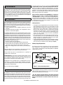

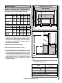
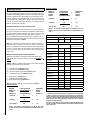
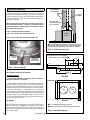


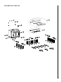
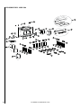
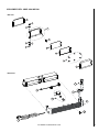
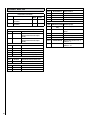
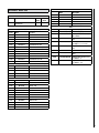
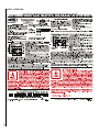


![Manuel installation fry top gaz LOTUS ga[...]](http://vs1.manualzilla.com/store/data/006143018_1-559f459d9628e988094a0727d9788a10-150x150.png)