1
WS-1913U-IT WEATHE
W
ER CENTER
Instruc
ction Man
nual
Congratullations on purrchasing this state-of-the-a
art weather sttation as an e
example of exxcellent design
n and
innovative
e measuring technique.
t
Fe
eaturing time, date, calenda
ar, weather fo
orecast, wind gust and win
nd
speed, ind
door/outdoor temperature and outdoor humidity,
h
air p
pressure and rainfall (optio
onal), this wea
ather
station will provide you
u with various weather inforrmation and w
weather foreccast. Pages after pages, yo
ou
will discov
ver that the op
peration of yo
our weather station is simp
ple!
Th
his product offerrs:
IN
NSTANT TRAN
NSMISSION is the state-of-th
he-art new
wireless transm
mission techno
ology, exclusiively designed
d
an
nd developed by LA CROSS
SE TECHNOLO
OGY. INSTAN
NT
TR
RANSMISSION
N offers you a
an immediate u
update (every
y
4.5 seconds!) (6
6.25 seconds for rain senso
or - optional) o
of
or data measurred from the ttransmitters:
all your outdoo
ollow your clim
matic variation
ns in real-time
e!
fo
1
INVENTORY OF CONTENTS
1. Wireless Weather Station WS-1913U-IT
2. Wireless Thermo-hygro Sensor (TX31U-IT) and Wind Sensor (TX55U-IT) with mounting bracket.
3. Instruction Manual
FEATURES:
The Weather Station
Battery
compartment
cover
LCD
Function keys
Time display (manual setting)
12/24 hour time display
Calendar display (weekday, date, month)
Weather forecast icons and weather tendency indicator
Indoor temperature display in °C/ºF
Outdoor temperature display in °C/ºF
Outdoor Humidity display as RH%
Dew point displayed in °C or °F
Wind chill displayed in °C of °F
Wind gust displayed in km/h, mph or m/s
Wind speed displayed in km/h, mph or m/s
24-hour and total rainfall displayed in mm or inch (optional)
Display MIN/MAX value of outdoor temperature, outdoor humidity, dew point, wind chill, and relative
air pressure, with time & date of recording
Display MAX wind speed and gust with time & date of recording
Relative air pressure displayed in hPa or inHg
Air pressure tendency indicator for the past 12 hour (bar graph format)
Manual reset of outdoor temperature/ humidity, pressure and wind chill data
LCD contrast selectable
Low battery indicator
Storage of 140 sets of history weather data recorded in 3-hour intervals
Wireless transmission at 915 MHz
Transmission range up to 330 feet/100 meters
The Thermo-hygro Transmitter
Remote transmission of the outdoor temperature and humidity to the Weather Center at 915
MHz (open air)
Rain resistant casing
Wall mounting case (to be mounted vertically in a sheltered place. Avoid direct rain and
sunshine)
The Wind sensor
Connected to the thermo-hygro transmitter by cable
Can be installed onto a mast or a horizontal panel (with the cups on the
bottom)
The TX32U-IT rain sensor (optional- sold separately)
2
Remotte transmissio
on of the rainffall data to the
e Weather Ce
enter at 915 M
MHz
To be mounted onto
o a horizonta l panel
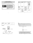
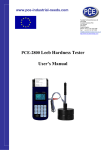
SET UP:
Weather center
OPT
TIONAL
Wire
eless transmissio
on at 915
MHzz – Rain sensor tto
weather station
Socket for
wind
Wireless
a 915
transmission at
MHz - thermo-hygro
transmitter to
weather stattion
Rain sens
sor (optional)
Therm
mo-hygro
transmitter
Ca
able connection between
b
the wind
d
sensor and the the
ermo-hygro
Wind se
ensor
IMPORTA
ANT:
- Do Not Mix Old and New Batterie
es
- Do Not Mix Alkaline, Standard, or
o Rechargea
able Batterie
es
NOTE:
When first operating th
he Weather Sttation, it is important to com
mpletely set-u
up the wiring and the rest of the
system in close proxim
mity (e.g. on a table 5ft-10ftt from displayy) and test all components for correct
function before
b
mounting them at their final destinations (See Positioning b
below) (Allow all sensors to
o sit
with the display unit forr 15 minutes before mountting)
1. First, unwind the cables of the Wind
W
sensor. Connect the Wind sensor to the Therm
mo-hygro
transm
mitter by plugging the conn
nector head in
nto the socke
et of the Therm
mo-hygro sen
nsor. Be sure the
cord “clicks”
“
into pllace.
2. Next, insert the battteries into the
e Thermo-hyg
gro sensor an
nd Rain senso
or (optional - purchased
separrately) See “H
How to install and replace
e the batterie
es into the Thermo-hygro
o sensor“ and
“How to install an
nd replace the batteries in
nto the Rain sensor (optional)” below
w.
3. Then insert the battteries into the
e Weather Ce
enter (See “H
How to installl and replace
e the batterie
es
into the Weather Center” below
w). Once the batteries are installed, all segments of the LCD will light
up briiefly. It will the
en display the
e time as 12:0
00, the date a
as 1.1.09, the weather icon
ns, and air
pressure value. "- - -" will be sho
own for outdo
oor data.
4. The Weather
W
Centter will start re
eceiving data from the tran
nsmitter. The ttransmission reception ico
on will
be blinking to indic
cate that the station
s
is trying to get the th
hermo-hygro transmitter data. The outd
door
erature, humid
dity, wind datta will be disp
played on the Weather Cen
nter. If this do
oes not happe
en
tempe
after 135
1 seconds, remove the batteries
b
from
m all units. Yo
ou will have to
o start again frrom step 2.
5. The trransmitter rec
ception icon is
s now blinking
g again to ind
dicate that the
e station is tryying to get the
e rain
senso
or data. It will stop blinking once the rain
n sensor has been detecte
ed. If this doess not happen after
135 seconds, you will
w need to start again from
m step 2. (op
ptional rain ga
auge).
3
6. Check the cable for correct connection and test all the components for correct functionality by
manually turning the wind-gauge; tilting the optional rain sensor to hear the impact of the internal
moving seesaw, etc. (See Positioning below).
7. Time and date must be manually set (See Manual Setting below).
8. After the Weather Center has been tested and found fit, the initial set up of the weather station
system is finished and the mounting of the system components can take place. Ensure that all
components work properly together at their chosen mounting or standing locations before permanent
mounting.
For example, if there appears to be problems with the 915 MHz radio transmissions, they can often
be overcome by slightly changing the mounting locations or turning the base station.
NOTE:
The radio communication between the receiver and the transmitters in the open field reaches distances of
up to 330 feet/ 100 meters, provided there are no interfering obstacles such as buildings, trees, vehicles,
high voltage lines, etc.
9. Radio interferences created by cordless phones, PC screens; radios or TV sets can in some cases
entirely cut off radio communication. Please consider this when choosing standing or mounting
locations.
NOTE:
After batteries are installed in the transmitter, install the batteries in the weather center to receive the
signal from the transmitters as soon as possible. If the weather center is powered more than 5 hours
after the transmitter is powered, the weather center will never receive signal successfully from the
transmitters. In this case, you will need to reinstall the batteries from all the transmitters to redo set-up
procedure.
After batteries are installed, there will be synchronization between Weather Center and the
transmitters. At this time, the signal reception icon will be blinking. When the signal is successfully
received by the Weather Center, the icon will be switched on (If it is not successful, the icon will
not be shown).
The short blinking of the icon shows that a reception is in progress.
Transmitter signal
reception icon
If the signal reception is not successful on the first frequency (915MHz) for 45 seconds, the frequency
is changed to 920MHz and the learning is tried another 45 seconds. If still not successful, the
reception is tried for 45 seconds on 910MHz. This will also be done for re-synchronization.
HOW TO INSTALL AND REPLACE THE BATTERIES INTO THE THERMO-HYGRO TRANSMITTER
The outdoor Thermo-hygro transmitter works with 2 x AA IEC LR6, 1.5V batteries. To
install and replace the batteries, please follow the steps below:
1. Remove the airflow cover of the transmitter.
2. Remove the battery compartment cover.
3. Insert the batteries, observing the correct polarity (see the marking in the battery
compartment).
4. Replace the battery cover and the airflow cover onto the unit.
4
NOTE:
When changing batteries in any of the units, all units need to be reset by following the setting up
procedures. This is because the thermo-hygro sensor at start-up assigns a random security code and this
code must be received and stored by the Weather Center in the first several minutes of power being
supplied to it.
HOW TO INSTALL AND REPLACE THE BATTERIES INTO THE WEATHER STATION
The Weather Station works with 2 x C, IEC LR14 1.5V batteries. When the batteries need to be replaced,
the low battery symbol will appear on the LCD.
To install and replace the batteries, please follow the steps below:
1.
Remove the battery compartment cover.
2.
Insert the batteries observing the correct polarity (see the marking
in the battery compartment).
3.
Replace the battery cover.
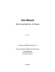
HOW TO INSTALL AND REPLACE BATTERIES INTO THE RAIN SENSOR (OPTIONAL; SOLD
SEPERATELY)
Figure 1
Figure 2
1.
2.
3.
4.
Figure 3
Unlock the main cover from the rain sensor base and remove the cover.
Remove the battery cover at the top of the rain sensor.
Insert 2 x AAA IEC LR3 1.5V batteries into the battery compartment, observing the correct polarity.
Replace the battery cover and the main cover on the unit.
NOTE:
When changing batteries in any of the units, all units need to be reset by following the setting up
procedures. This is because the transmitter and rain sensor (optional) assign a random security code at
start-up and these codes must be received and stored by the Weather Station in the first 90 seconds of
power being supplied to it.
BATTERY CHANGE:
It is recommended to replace the batteries in all units regularly to ensure optimum accuracy of these units.
(For battery life information, see the Specifications section)
Please participate in the preservation of the environment. Return used batteries to an
authorised depot.
- Do Not Mix Old and New Batteries
- Do Not Mix Alkaline, Standard, or Rechargeable Batteries
NOTE:
The stored History record is lost when a battery change is completed on the weather station.
FUNCTION KEYS:
Weather Station:
The Weather Station has 4 easy-to-use function keys.
SET key
+ key
MIN/MAX key
HISTORY key
5
SET key
Press and hold to enter manual setting modes: LCD contrast, Manual time setting, 12/24 hour time
display, Calendar setting, ºC/ ºF temperature unit, Wind speed unit, Rainfall unit, Pressure unit,
Relative pressure reference setting, Weather tendency threshold, Storm threshold setting
Press to toggle between Mode 1 and Mode 2:
- Mode1: "Wind speed + outdoor temp + rel. pressure"
- Mode 2: "Gust + Dew Point temp + rainfall data (only if there is a rain sensor- optional)"
(Mode 2 is shown for 30 seconds. Then it returns to the normal display)
Press to activate the reset mode when MAX or MIN record is shown
+ key
In display Mode 1, press to toggle between the display of date, weekday + date, Indoor temp, or
second
In display Mode 2, press to toggle between the display of Relative Pressure, 24 hour rainfall and Total
rainfall (only if there is a rain sensor- optional).
Press to adjust (increase) the level of different settings
Press to confirm to reset the MIN/MAX record
HISTORY key
Press to display the weather data history records
Press to exit manual setting mode
MIN/MAX key
Press to display MIN/MAX records of various weather data
Press to adjust (decrease) the level of different settings
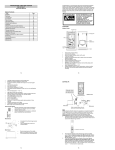
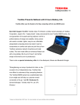
LCD SCREEN
The LCD screen is split into 3 sections displaying the following information:
1.
2.
3.
Time and date/ indoor temp/ second
Wind data, outdoor temperature and humidity, dew point, weather forecast icon and tendency
indicator
Air pressure history, relative air pressure, rainfall data (optional)
Calendar / indoor
temperature / seconds
display
Wind speed / gust** in mph,
km/h, m/s
Time display
Wind Chill in °C or °F
Weather forecast
Icon
Weather tendency
Indicator
Low battery indicator
(weather station)
Outdoor temperature
/ dew point**
In C or F
Outdoor relative
humidity in %
Transmitter signal
reception icon*
Low battery indicator
*(transmitter)
Air pressure
History histogram
MIN/MAX icons
HISTORY
icon
Low battery indicator
(rain sensor - optional)
Relative air pressure / 24 hr
rainfall / Total rainfall display*
(only if there is a rain sensor
being used)
* When the signal from the transmitter/ or rain sensor (optional) is successfully received by the Weather
Station, this icon will be switched on. (If not successful, the icon will not be shown on the LCD). User can
therefore easily see whether the last reception was successful (“ON” icon) or not (“OFF” icon). On the
other hand, the short blinking of the icon shows that a reception is being done at that time.
6
** In normal display mode, user may press the SET key to toggle between Mode1 and Mode 2 display:
Mode 1: Wind speed, outdoor temperature, relative air pressure are shown.
Wind speed icon
Outdoor temp
icon
Rel. Air Pressure icon
In Mode 1, this reception icon is showing the condition of the reception of
the signal from Thermo-hygro transmitter
Mode 2: Wind gust, dew point, and rainfall (optional) reading are shown.
Note: To view the rainfall data, press the + key after entering Mode 2 display.
Wind gust icon
Dew point icon
Rain icon
In Mode 2, this reception icon is showing the
condition of the reception of the signal from Rain
sensor (only if a rain sensor is being used).
MANUAL SETTINGS:
Note: if no rain sensor is used, the reception icon
will always be displayed in Mode 2.
The following manual settings can be changed once the SET key is pressed and held for about 3 seconds:
LCD contrast setting
Manual time setting
12/24 hour time display
Calendar setting
°C/ °F temperature unit setting
Wind speed unit
Rainfall unit setting
Air pressure unit setting
Relative pressure reference value setting
Weather tendency threshold value
Storm warning threshold value
LCD CONTRAST SETTING
Digit flashing
The LCD contrast has 8 levels, from "LCD 1" to "LCD8" (default setting is LCD 5):
1. Press the SET key, the contrast level digit will flash.
2. Use the + or MIN/MAX key to adjust the level of contrast.
3. Confirm with the SET key and enter the MANUAL TIME SETTING.
7
MANUAL TIME SETTING:
You then may manually set the time by following the steps below:
Minutes Flashing
Hour Flashing
1.
2.
3.
4.
5.
The hour digit will flash.
Use the + or MIN/MAX key to set the hour.
Press the SET key to switch to the minutes. The minute digit will flash.
Use the + or MIN/MAX key to set the minutes (holding of the key will forward the digit by 5).
Confirm the time with the SET key and enter the 12/24-HOUR TIME DISPLAY SETTING.
12/24 HOUR TIME DISPLAY SETTING:
Digit flashing
The time can be set to view as 12-hour or 24-hour format. The default time display mode is “12h”. To set
to “24h” time display:
1. Use the + or MIN/MAX key to toggle the value.
2. Confirm with the SET key and enter the CALENDAR SETTING.
"Month. Date." (for 12h time display)
"Date. Month." (for 24h time display)
CALENDAR SETTING:
Year
The date default of the Weather Station is 1. 1. of year 2009. The date can be set manually by proceeding
as follows.
1. The year digit will flash.
2. Use the + or MIN/MAX key to set the year (pressing and holding the key will forward the digit by 5).
The range runs from "00" (2000) to "99" (2099).
3. Press the SET key to confirm the year and enter the month setting. The month digit will flash.
4. Use the + or MIN/MAX key to set the month.
5. Press the SET key to confirm the month and enter the date setting mode. The date digit will flash.
6. Use the + or MIN/MAX key to set the date.
7. Confirm all calendar settings with the SET key and enter the °C/°F TEMPERATURE UNIT SETTING.
°C/°F TEMPERATURE UNIT SETTING
Flashing
The temperature display can be selected to show temperature data in °F or °C. (Default °F)
1. The temperature unit is flashing
2. Use the + or MIN/MAX key to toggle between “°F” or “°C”.
3. Confirm with the SET key and enter the WIND SPEED UNIT SETTING
WIND SPEED UNIT SETTING
Flashing
8
The wind speed unit can be set as mph (mile per hour), km/h (Kilometer per hour), or m/s (meter per
second). The default unit is mph.
1. Use the + or MIN/MAX key to toggle between the unit “mph”, “km/h”, or “m/s”
2. Confirm with the SET key and enter the RAINFALL UNIT SETTING.
RAINFALL UNIT SETTING (OPTIONAL)
Note: the rain unit setting is only available if there is a rain sensor. Skip this setting by pressing the SET
key again to enter the Relative Air Pressure Unit Setting.
Flashing
The total rainfall unit can be set as inch or mm. The default unit is inch.
1. Use the + or MIN/MAX key to toggle between the unit “mm” or “Inch”
2. Confirm the unit with the SET key and enter the RELATIVE AIR PRESSURE UNIT SETTING
RELATIVE AIR PRESSURE UNIT SETTING
Flashing
The relative air pressure can be set as hPa of inHg. The default unit is inHg.
1. Use the + or MIN/MAX key to toggle between the unit “hPa" or “inHg”
2. Confirm the unit with the SET key and enter the RELATIVE PRESSURE REFERENCE VALUE
SETTING.
RELATIVE PRESSURE REFERENCE VALUE SETTING
NOTE:
The default reference pressure value of the barometer is 29.91inHg (1013 hPa) when batteries are first
inserted. For an exact measurement, it is necessary to first adjust the barometer to your local
relative air pressure (related to elevation above sea level). Ask for the current atmospheric pressure
of your home area (Local weather service, www, calibrated instruments in public buildings, airport).
The relative air pressure can be manually set to another value within the range of 27.14 to 31.90 inHg
(919 to 1080 hPa) for a better reference.
Flashing
1. The current relative pressure value will flash.
2. Use the + or MIN/MAX key to increase or decrease the value. Keep holding the key will allow the
value to increase faster.
3. Confirm with the SET key and enter the WEATHER TENDENCY THRESHOLD VALUE SETTING.
NOTE:
This calibration facility is useful for those users living at various elevations above sea level, but wanting
their air pressure display to be based on sea level elevation.
WEATHER TENDENCY THRESHOLD VALUE SETTING
Flashing
9
nite switching sensitivity va
alue, .06, .09, or .12 inHg (2-4 hPa) for tthe change in
n the
You may select a defin
display off weather icon
ns. This represents the "se
ensitivity" of th
he weather fo
orecast (the sm
maller the value
selected, the more sen
nsitive the wea
ather forecas
st). The defau
ult value is 0.0
09 inHg (3 hP
Pa).
1.
2.
3.
The threshold
t
valu
ue will flash.
Use the
t + or MIN//MAX key to select
s
the valu
ue.
Conffirm with the SET
S
key and enter
e
the STO
ORM WARNING THRESH
HOLD VALUE
E SETTING.
W
TH
HRESHOLD VALUE
V
SETT
TING
STORM WARNING
You may also define a switching sensitivity value
e for the Storm
m warning dissplay at a deccrease of air
pressure from
f
.09 inHg
g to .27 inHg (3-9
(
hPa) ove
er 6 hours (De
efault 0.15 inH
Hg (5 hPa)).
Flashing
1.
2.
3.
The threshold
t
valu
ue will flash.
Use the
t + or MIN//MAX key to select
s
the valu
ue.
Conffirm with the SET
S
key and enter
e
the STO
ORM ALARM
M ON/ OFF SE
ETTING.
A
ON/ OFF
O SETTING
STORM ALARM
Note: the
e storm alarm
m ON/OFF se
etting is not available
a
on this model. S
Skip and exit this setting
g by
pressing the SET key
y.
TO EXIT THE
T
MANUA
AL SETTING MODE
To exit the
e manual settting anytime during
d
the ma
anual setting m
modes, presss the HISTOR
RY key anytim
me or
wait for th
he automatic timeout.
t
The mode
m
will retu
urn to the norrmal time disp
play.
STORM WARNING
W
IC
CON: When th
he storm-warn
ning threshold
d is reached, you will see tthe cloud with
h rain
icon and the
t down arro
ow will flash. There
T
is not an
a audible ala
arm.
ER FORECAS
ST AND WEA
ATHER TEND
DENCY
WEATHE
ER FORECAS
STING ICONS
S
WEATHE
Weather icons in the th
hird section off LCD can be
e displayed in any of the following comb
binations:
Sunny
Cloud
dy with sunny in
ntervals
Rainy
For every sudden or significant chan
nge in the air pressure, the
e weather ico
ons will update
e accordinglyy to
represent the change in weather. If the icons do not change, tthen it meanss either the airr pressure ha
as not
changed or
o the change
e has been to
oo slow for the
e Weather sta
ation to registter. However, if the icon
displayed is a sun or ra
aining cloud, there
t
will be no
n change of icon if the we
eather gets an
ny better (with
h
sunny icon) or worse (w
with rainy icon
n) since the ic
cons are alrea
ady at their e
extremes.
10
The icons
s displayed forecasts the weather
w
in term
ms of getting better or worrse and not ne
ecessarily sun
nny
or rainy as
s each icon in
ndicates. For example, if th
he current we
eather is cloud
dy and the rainy icon is
ng. It simply m
displayed, it does not mean
m
that the
e product is fa
aulty because it is not rainin
means that th
he air
pressure has dropped and the weatther is expected to get worrse but not ne
ecessarily rain
ny.
NOTE:
After set up,
u readings for
f weather fo
orecasts shou
uld be disrega
arded for the n
next 48-60 ho
ours. This willl
allow sufficient time forr the Weatherr station to co
ollect air presssure data at a constant altiitude and
therefore result in a mo
ore accurate forecast.
f
Common to weather fo
orecasting, ab
bsolute accura
acy cannot be
e guaranteed. The weathe
er forecasting
feature is estimated to have an accu
uracy level off about 75% d
due to the varrying areas th
he Weather sttation
has been designed for use. In areas
s that experie
ence sudden cchanges in we
eather (for exxample from ssunny
to rain), th
he Weather sttation will be more accuratte compared tto use in area
as where the weather is
stagnant most
m
of the tim
me (for example mostly su
unny).
If the Wea
ather station is moved to another locatio
on significantlly higher or lo
ower than its iinitial standing
point (for example from
m the ground floor
f
to the up
pper floors of a house), disscard the wea
ather forecastt for
the next 48-60
4
hours. By
B doing this, the Weatherr Station will n
not mistake th
he new locatio
on as being a
possible change
c
in air--pressure whe
en really it is due
d to the slig
ght change off altitude.
ER TENDENC
CY INDICATO
OR
WEATHE
Working together with the weather icons is the weather
w
tende ncy indicatorss (located on the left and rright
sides of th
he weather icons). When the indicator points
p
upward
ds, it means th
hat the air-pre
essure is
increasing
g and the wea
ather is expec
cted to improv
ve, but when indicator poin
nts downward
ds, the airpressure is dropping and the weathe
er is expected
d to become w
worse.
Taking thiis into accoun
nt, one can se
ee how the we
eather has ch
hanged and iss expected to change. For
example, if the indicato
or is pointing downwards
d
to
ogether with ccloud and sun
n icons, then the last noticeable
change in
n the weather was when it was
w sunny (th
he sun icon o
only). Therefore, the next cchange in the
weather will
w be cloud with
w rain icons
s since the ind
dicator is poin
nting downwa
ards.
NOTE:
Once the weather tend
dency indicato
or has registe
ered a change
e in air pressu
ure, it will rem
main permanently
visualized
d on the LCD.
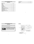
AIR PRES
SSURE HIST
TORY (ELECT
TRONIC BAR
ROMETER W
WITH BAROM
METRIC PRES
SSURE TREN
ND)
The bottom section of the
t LCD also shows the re
elative air presssure value a
and the air pre
essure historyy.
The bar graph of the electronic baro
ometer shows
s the air presssure history o
of the past 12 hours in five 3hour steps
s.
Air pressure
anges in hPa
cha
Air pre
essure
changes in
n inHg
The horizo
ontal axis rep
presents the la
ast 12 hours air
a pressure rrecording (-12
2, -9, -6, -3 an
nd 0 hour). Th
he
bars are plotted
p
at each of the 5 ste
eps and give the trend overr the recorded
d period. The scale on the right
compares
s the result. The "0" in the middle
m
of this
s scale determ
mines the currrent air pressure.
The vertic
cal axis repres
sents the air pressure
p
chan
nges in inHg (+0.12, +0.06
6, 0, -0.06, -0.12. The “0”
represents the current air pressure). The newly measured
m
pre
essure was co
ompared to th
he
previously
y recorded pre
essure readin
ng. The press
sure change iss expressed b
by the difference between the
current ("0
0h") and the past
p
readings
s in division off ±2 hPa or ±0
0.06 inHg. If tthe bars are rrising it indica
ates
that the weather
w
is gettting better due to an increa
ase in air presssure. If the b
bars go down it indicates a drop
of the air pressure and the weather is expected to get worse ffrom the prese
ent time "0".
At every full
f hour, the current
c
air pre
essure is used
d as a basis ffor the displayy of a new gra
aph bar. The
existing graph is then moved
m
one co
olumn to the left.
11
NOTE:
For accurate barometric pressure trend, the Weather Center should operate at the same altitude. For
example, it should not be moved. Should the unit be moved, for instance from the ground to the second
floor of the house, the readings for the next 48-60 hours shall be discarded..
WIND SPEED MEASUREMENT
In normal display mode, the second section of the LCD shows the following wind data.
Wind chill in F or C
Wind Speed in km/h, mph or m/s
Gust in km/h, mph or m/s (displayed when in Mode 2, by pressing the SET key shortly)
Wind speed or
Gust will be shown
Wind chill
RAINFALL MEASUREMENT (OPTIONAL)
The total rainfall and 24 hour rainfall measurement is displayed in the last section of the LCD (where
pressure is normally displayed), in the unit of mm or inch.
To View the 24-hour rainfall or the Total rainfall reading:
1. In normal display, press SET key once and the display will shift to Mode 2.
2. Press + key consecutively key to toggle between the 24-hour rainfall, Total rainfall and Rel. pressure
reading.
24 hour rainfall icon
24 hour rainfall amount
Total rainfall icon
Total rainfall amount
VIEW THE HISTORY DATA
The weather station can store up to 140 sets of weather data which are recorded automatically at 3-hour
intervals after the weather station is powered up, at the nearest time of 0:00, 03:00, 06:00, 09:00, 12:00,
15:00, 18:00 and 21:00. For instance, if user has manually set the time as 14:52 after installing batteries,
the first history record will be made at the coming 15:00 automatically. Then the second record will be on
18:00 and so on.
Each weather record includes the Wind direction, Wind speed/ gust, Wind chill temperature, wind
speed/gust, dew point, Outdoor temp and humidity, relative pressure, 24-hour rainfall and total rainfall,
pressure history and weather tendency. Also, the time and date of recording will be displayed.
NOTE:
In order to acquire the correct time of recording of the history records, you shall manually set the current
time as soon as installing batteries to the weather station. Afterwards, you should avoid changing the preset time as it will also alter the recorded "time of recording" of each history record, which may lead to
confusion.
To view the weather history:
1. In normal display, press the HISTORY key. The latest weather record will be shown with the date and
time of recording. The "HISTORY" icon will be displayed at the bottom of the LCD.
2. When viewing History records, user may shift to see the Mode 1 or Mode 2 data by pressing the SET
key.
Mode 1: with wind speed + outdoor Temp + Rel. pressure;
Mode 2: with wind gust + Dew point + rainfall data (optional)
12
NOTE: To view total rainfall or 24-hour rainfall in history records, first, in normal display mode, choose to
show the particular rainfall data, then press the History key followed by the SET key to view the particular
rainfall data in History records. (rain data information only available if a rain sensor is being usedoptional).
HISTORY icon
3. When viewing History records, press MIN/ MAX to view older records.
(Press MIN/MAX and + key to view "Previous" and "Next" record respectively. The records are made
at 3-hour intervals)
NOTE:
The stored history records will be lost after battery change or whenever battery is removed.
The total rainfall value will be exhibited in whole number (no decimal place) in the history record.
VIEW THE MAXIMUM/MINIMUM WEATHER DATA
The weather station will record the minimum and maximum value of the various weather data with time
and date of recording automatically. The following stored maximum and minimum weather data can be
viewed by pressing the MIN/MAX key in normal display mode.
1. MIN outdoor temperature with the date and time of recording
Time and date or
recording
MIN outdoor
temperature value
2. MAX outdoor temperature with the date and time of recording
MIN icon
3. MIN dew point temperature
Time and date or
recording
MIN Dew Point
temp
MIN icon
13
4. MAX dew point temperature
5. MIN outdoor humidity with the date and time of recording
Time and date of
recording
MIN outdoor
humidity value
MIN icon
6. MAX outdoor humidity with the date and time of recording
7. MIN Wind chill temperature with the date and time of recording
Time and date of
recording
MIN wind
chill value
MIN icon
8. MAX Wind chill temperature with the date and time of recording
9. MIN Relative pressure with the date and time of recording
10. MAX Relative pressure with the date and time of recording
Time and date or
recording
MAX relative
pressure value
MAX icon
11. MAX wind speed with the date and time of recording
Time and date of recording
MAX wind speed
value
MAX icon
14
12. MAX Gust with the date and time of recording
Time and date of
recording
MAX Gust value
MAX icon
13. MAX 24 hour rainfall (optional) with the date and time of recording
The 24h rainfall value
is counted from this
time and date
24h rainfall
amount
24 hour
rainfall icon
RESET MAXIMUM AND MINIMUM WEATHER DATA
To reset the maximum or minimum weather data 1 to 13, you will need to reset each of the data
independently.
1. Press MIN/MAX key to show the desired weather data. For instance, if you want to reset the minimum
humidity, in the normal display you shall press the MIN/MAX key three times to show the min humidity
value.
2. Press and hold the SET key for about 2 seconds, then the "RESET" icon will appear at the bottom
part of the LCD.
3. Press the + key once, then the stored value will be reset to the current value and current time.
4. Press the HISTORY key to return to normal display mode.
Total rainfall amount (optional) with the date and time of recording
The total rainfall measurement is displayed in the last section of the LCD, in the unit of mm or inch. It
shows the total rainfall accumulated since last reset of the weather station.
In normal display mode, press the MIN/MAX key fourteen times to show the total rainfall value. The
"RESET" icon will also be shown at the same time.
The total rainfall value
is counted from this
time and date
Total rainfall icon
Total rainfall
amount
15
To reset the rainfall reading:
- Press the + key once when the Rainfall value and Reset icon are shown.
- Then the total rainfall amount will be reset to 0, and the time updated to current time.
NOTE:
After power up, the time and date and total rainfall are displayed as "- - -". After time is adjusted manually,
the set time will be shown.
LOW BATTERY INDICATOR
The low battery indicator of the weather station and the transmitter will be displayed in the second section,
and the low battery icon for the rain sensor (optional) will be shown on the last section of the LCD
respectively when the battery power is low. It is recommended to replace the batteries in all units on an
annual basis to ensure optimum accuracy of the system.
NOTE:
After battery change, both the Weather Station and the transmitters need to be reset (see note ”Set
up”)
The History data record will be clear after the battery change.
OUTDOOR TRANSMITTER 915 MHz RECEPTION CHECK
The outdoor temperature, humidity, wind data are transmitted from thermo-hygro transmitter every 4.5
seconds; the rainfall data are transmitted from the rain sensor (optional) every 6.25 seconds. The receiver
will synchronize to the thermo-hygro transmitter and rain sensor (optional) then. The transmission range
(up to about 330 feet /100 meters in open air) of the thermo-hygro transmitter/ rain sensor may be
affected by the ambient temperature. At cold temperatures, the transmitting distance may decrease.
Please keep this in mind when placing the transmitter and the rain sensor.
If (1) the outdoor data is not being received within first several minutes after set up; (2) the outdoor
display always shows “- - -“ on the outdoor display; or (3) the reception icon of thermo-hygro transmitter
(Mode 1) and rain sensor (optional) (Mode 2) is not displayed on the display, check the following things:
1. The distance of the Weather Station or transmitter/ rain sensor should be at least 5 to 6.5 feet (1.5 to
2 meters) away from any interfering sources such as computer monitors or TV sets.
2. Avoid positioning the Weather Center onto or in the immediate proximity of metal doors or window
frames.
3. Using other electrical products such as headphones or speakers operating on the same signal
frequency (915 MHz) may prevent correct signal transmission and reception.
4. Neighbors using electrical devices operating on the 915 MHz signal frequency can also cause
interference.
NOTE:
When the 915 MHz signal is received, do not re-open the battery compartment cover of the transmitter/
rain sensor or Weather station, as the batteries may spring free from the contacts and force a false reset.
Should this happen accidentally then reset all units (see Set up above) otherwise transmission problems
may occur.
During normal operation, after the outdoor display shows "- - -", the weather station will change to receive
the outdoor data every 15 minutes, until the data is read. Then the reception period for thermo-hygro
transmitter will return to 4.5 seconds (6.25 seconds for rain sensor - optional).
If no reception is possible despite the observation of these factors, all system units have to be reset (see
Set up).
POSITIONING:
Prior to permanently mounting any of the units, please ensure the following points are considered:
Cable lengths of the units meet with your distance requirements at the point of fixing
Signals from the sensors can be received by the base station at points of mounting
La Crosse Technology Sensor Extension Cable
You can purchase a La Crosse Technology Extension Cable if you require additional length to properly
mount your sensor. The extension cable is 32 feet in length and comes with the appropriate connecter
16
attached. Please visit your local retailer or www.lacrossetechnology.com and click on the Buy button to
locate an online dealer or other retailers.
Using phone cables or connections may damage your sensors because phone cables and connections
have more resistance than the La Crosse Technology extension cable. Phone cables or connections are
not recommended for use.
NOTE: Using extension cables will shorten battery life.
Warning: Never cut, splice, shorten or modify your sensor cables or extension cables. Doing so may
damage your sensors and will void your warranty.
The Weather Station
The Weather Station is designed to be free standing only.
The Thermo-hygro Sensor
Rain Cover
Main Unit
Wall Bracket
An ideal mounting place for the thermo-hygro sensor would be the outer wall beneath the extension of a
roof, as this will protect the sensor from direct sunlight and other extreme weather conditions. Be sure to
mount vertically.
To wall mount, use the 2 screws to affix the wall bracket to the desired wall, plug in the thermo-hygro
sensor to the bracket and secure both parts by the use of the supplied screw and ensure that the cable
from the wind sensor is correctly plugged in otherwise data transmission errors could occur.
The Wind Sensor
Vertical mast
Wind -cups
Horizontal panel
Check that the wind-cups can rotate freely before fixing the unit. For correct and accurate readings, it is
important to mount the sensor with the cups on the bottom. The wind sensor should now be mounted
using the screw or cable tie provided onto a solid wall/ panel mast or mast to allows the wind to travel
around the sensor unhindered from all directions (ideal mast size should be from diameter 0.62” to 1.29”
(16mm to 33mm). Do not over tighten the mounting bracket
.
17
Once the wind sensor is fixed onto the mast, connect the cable to the corresponding thermo-hygro sensor
socket so that operating power supply can be received and data can be transmitted to the base station.
Secure cord from blowing. Do not use staples. Using PVC pipe or metal as a mast may cause static.
Wood is recommended.
The Rain Sensor (optional)
Horizontal panel
For best results, the rain sensor should be securely mounted onto a horizontal surface about 39.37” (1
meter) above the ground (or higher) and in an open area away from trees or other coverings where
rainfall may be reduced causing inaccurate readings.
When securing into place, check that rain excess will not collect and store at the base of the unit but can
flow out between the base and the mounting surface (test by pouring clean water). Do not tighten screws
past just snug.
After mounting the rain sensor and placing battery, the rain sensor is now operable. For testing purposes,
very slowly pour a small amount of clean water into the rain sensor funnel. The water will act as rainfall
and will be received and displayed at the base station i.e. when the reading interval is reached.
CARE AND MAINTENANCE:
Do Not Mix Old and New Batteries
Do Not Mix Alkaline, Standard, or Rechargeable Batteries
Extreme temperatures, vibration and shock should be avoided as these may cause damage to the
unit and give inaccurate forecasts and readings.
Precautions shall be taken when handling the batteries. Injuries, burns, or property damage may be
resulted if the batteries are in contact with conducting materials, heat, corrosive materials or
explosives. The batteries shall be taken out from the unit before the product is to be stored for a long
period of time.
Immediately remove all low powered batteries to avoid leakage and damage. Replace only with new
batteries of the recommended type.
When cleaning the display and casings, use a soft damp cloth only. Do not use solvents or scouring
agents as they may mark the LCD and casings.
Do not submerge the unit in water.
Special care shall be taken when handling a damaged LCD display. The liquid crystals can be
harmful to user's health.
Do not make any repair attempts to the unit. Return them to their original point of purchase for repair
by a qualified engineer. Opening and tampering with the unit may invalidate their guarantee.
Never touch the exposed electronic circuitry of the device, as there is danger of electric shock, should
it become exposed.
Do not expose the units to extreme and sudden temperature changes, this may lead to rapid changes
in forecasts and readings and thereby reduce their accuracy.
SPECIFICATIONS:
Temperature measuring range:
Indoor:
32° F to +139.8° F with 0.2° F resolution
0º C to +59.9º C with 0.1º C resolution
(Displays “OF.L” if outside this range)
Outdoor / dew point: -40° F to +139.8°F with 0.2° F resolution
-40º C to +59.9º C with 0.1º C resolution
(Displays “OF.L” if outside this range)
18
Relative humidity measuring range:
Outdoor:
1% to 99% with 1% resolution
(Displays “- -” if < 1%, "99" Displays if 99%)
Wind speed/ gust:
0 to 111.8 mph (0 to 180km/h; 0 to 50 m/s)
(Displays "OF.L" when > 111.8 mph; 180 km/h; 50m/s)
Wind chill/ dew point: -40°F to +139.8° F with 0.2° F resolution
-40ºC to +59.9º C with 0.1º C resolution
(“OF.L” displayed if outside this range)
Relative pressure pre-set range:
27.14 to 31.90 inHg (919 to 1080 hPa)
24h rainfall:
0" to 39.3" with 0.01” resolution
0 to 999.9 mm with 0.1mm resolution
Total rainfall:
0" to 393.7" with 0.01” resolution
0 to 9999 mm with 0.1mm resolution
(Displays "OF.L" when > 9999mm)
When the total rainfall is higher than 1000mm (for mm unit only),
the resolution is changed to 1mm)
Outdoor data reception: Every 4.5 seconds (from thermo-hygro transmitter)
Every 6.25 seconds (from rain sensor-optional)
Air pressure checking interval:
Every 15 seconds
Transmission range:
Up to 330 feet (100 meters) in open space
Power consumption:
Weather Center:
2 x C, IEC LR14, 1.5V
Thermo-hygro transmitter: 2 x AA, IEC LR6, 1.5V
Rain sensor(optional) : 2 x AAA, IEC LR3, 1.5V
Battery life:
Approximately 24 months (Alkaline batteries recommended)
Dimensions (L x W x H):
Weather Center:
5.83" x 5.83" x 2.0" / 148 x 148 x 50.8mm
Thermo-hygro transmitter: 2.25” x 2.44” x 6.17” / 57.3 x 62 x 157mm
Wind sensor:
9.8” x 5.7” x 7.5” / 250 x 145.9 x 191.4mm
Rain sensor (optional):
5.67” x 2.15” x3.46” / 144 x 54.6 x 88mm
LIABILITY DISCLAIMER
The electrical and electronic wastes contain hazardous substances. Disposal of electronic waste in
wild country and/or in unauthorized grounds strongly damages the environment.
Please contact your local or/and regional authorities to retrieve the addresses of legal dumping
grounds with selective collection.
All electronic instruments must from now on be recycled. User shall take an active part in the reuse,
recycling and recovery of the electrical and electronic waste.
The unrestricted disposal of electronic waste may do harm on public health and the quality of
environment.
As stated on the gift box and labelled on the product, reading the “User manual” is highly
recommended for the benefit of the user. This product must however not be thrown in general rubbish
collection points.
The manufacturer and supplier cannot accept any responsibility for any incorrect readings and any
consequences that occur should an inaccurate reading take place.
This product is designed for use in the home only as indication of the temperature.
This product is not to be used for medical purposes or for public information.
The specifications of this product may change without prior notice.
This product is not a toy. Keep out of the reach of children.
No part of this manual may be reproduced without written authorization of the manufacturer.
19
WARRANTY INFORMATION
La Crosse Technology, Ltd provides a 1-year limited warranty on this product against manufacturing
defects in materials and workmanship.
This limited warranty begins on the original date of purchase, is valid only on products purchased and
used in North America and only to the original purchaser of this product. To receive warranty service, the
purchaser must contact La Crosse Technology, Ltd for problem determination and service procedures.
Warranty service can only be performed by a La Crosse Technology, Ltd authorized service center. The
original dated bill of sale must be presented upon request as proof of purchase to La Crosse Technology,
Ltd or La Crosse Technology, Ltd’s authorized service center.
La Crosse Technology, Ltd will repair or replace this product, at our option and at no charge as stipulated
herein, with new or reconditioned parts or products if found to be defective during the limited warranty
period specified above. All replaced parts and products become the property of La Crosse Technology,
Ltd and must be returned to La Crosse Technology, Ltd. Replacement parts and products assume the
remaining original warranty, or ninety (90) days, whichever is longer. La Crosse Technology, Ltd will pay
all expenses for labor and materials for all repairs covered by this warranty. If necessary repairs are not
covered by this warranty, or if a product is examined which is not in need or repair, you will be charged for
the repairs or examination. The owner must pay any shipping charges incurred in getting your La Crosse
Technology, Ltd product to a La Crosse Technology, Ltd authorized service center. La Crosse
Technology, Ltd will pay ground return shipping charges to the owner of the product to a USA address
only.
Your La Crosse Technology, Ltd warranty covers all defects in material and workmanship with the
following specified exceptions: (1) damage caused by accident, unreasonable use or neglect (including
the lack of reasonable and necessary maintenance); (2) damage occurring during shipment (claims must
be presented to the carrier); (3) damage to, or deterioration of, any accessory or decorative surface; (4)
damage resulting from failure to follow instructions contained in your owner’s manual; (5) damage
resulting from the performance of repairs or alterations by someone other than an authorized La Crosse
Technology, Ltd authorized service center; (6) units used for other than home use (7) applications and
uses that this product was not intended or (8) the products inability to receive a signal due to any source
of interference.. This warranty covers only actual defects within the product itself, and does not cover the
cost of installation or removal from a fixed installation, normal set-up or adjustments, claims based on
misrepresentation by the seller or performance variations resulting from installation-related circumstances.
LA CROSSE TECHNOLOGY, LTD WILL NOT ASSUME LIABILITY FOR INCIDENTAL,
CONSEQUENTIAL, PUNITIVE, OR OTHER SIMILAR DAMAGES ASSOCIATED WITH THE
OPERATION OR MALFUNCTION OF THIS PRODUCT. THIS PRODUCT IS NOT TO BE USED FOR
MEDICAL PURPOSES OR FOR PUBLIC INFORMATION. THIS PRODUCT IS NOT A TOY. KEEP OUT
OF CHILDREN’S REACH.
This warranty gives you specific legal rights. You may also have other rights specific to your State.
Some States do no allow the exclusion of consequential or incidental damages therefore the above
exclusion of limitation may not apply to you.
For warranty work, technical support, or information contact:
La Crosse Technology, Ltd
2817 Losey Blvd. S.
La Crosse, WI 54601
Phone: 608.782.1610
Fax: 608.796.1020
e-mail: http://www.lacrossetechnology.com/support/home.php (warranty work)
Contact Support: 1-608-782-1610
Product Registration: www.lacrossetechnology.com/support/register.php
www.lacrossetechnology.com
For more information, please visit:
http://www.lacrossetechnology.com/1913twc/
20
All rights reserved. This handbook must not be reproduced in any form, even in excerpts, or duplicated or
processed using electronic, mechanical or chemical procedures without written permission of the
publisher.
This handbook may contain mistakes and printing errors. The information in this handbook is regularly
checked and corrections made in the next issue. We accept no liability for technical mistakes or printing
errors, or their consequences.
All trademarks and patents are acknowledged.
21