1
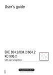
Installation Instructions
for LP Gas Unit
Dear Consumer!
Please keep this manual in a safe
place and pass it on to future
reference.
Dear Installer!
Please leave this instruction with
the appliance for the owner.
072429 I21
USA
GKS 644.0 / GKS 324.0
For your information...
Contents
Be sure to read the information in this manual carefully before you install the
cook top.
Disposing of the packaging and the old appliance. . . . . . . . . 2
Safety instructions . . . . . . . . . . . . . . . . . . . . . . . . . . . . . . 3
Installation . . . . . . . . . . . . . . . . . . . . . . . . . . . . . . . . . . . . 3
Please keep this manual in a safe place and pass it on to future owners for
their information and safety.
The following symbols are used in this operating manual:
warning triangle will alert you about possible health risks or things
[ The
that can cause potential damage to your appliance.
F
You’ll find useful hints and information when you see this symbol.
Warranty
This warranty is extended to the original purchaser and succeeding owners for
products purchased for ordinary home use. It does not cover its use in commercial situation. Should the appliance be sold by the original purchaser during
the warranty period, the new owner continued to be protected until the expiration date of the original purchaser’s warranty period. Save your dated receipt
or other evidence of the installation/occupancy date. Proof of original purchase
date is needed to obtain service under warranty. The warranty applies even if
the owner should move during the warranty period.
Requirements for installation
Gasket
Installation dimensions
Connecting the appliance to the gas supply
Leak testing
Connecting the appliance to the electricity supply
Installation
Initial start-up
Testing the appliance's functions
Technical data . . . . . . . . . . . . . . . . . . . . . . . . . . . . . . . . . 7
Table of heat input
Cross calorific value and pressure
For Service: removal and replacement
Küppersbusch does not assume any responsibility for consequential or incidental damages. This warranty provides you with certain legal rights. You may
also have other rights which may vary from state to state.
What Is Covered
For one full year from the date of the original purchase, we will provide parts,
service and labor in your home to repair or replace any part of the cook top
that fails because of a defect in materials or workmanship. This service is provided free of charge. All warranty service will be provided by an authorized
technician during normal business hours.
What Isn’t Covered
■
■
■
■
■
■
Service by an unauthorized agency will not be reimbursed. Likewise, the
warranty doesn’t cover any damage or repairs due to service performed by
an unauthorized agency, or by the use of unauthorized parts.
Service visits to teach you how to use the appliance.
Service visits to correct the installation. You are responsible for providing
electrical wiring and other connecting facilities.
Reset circuit breakers or replace home fuses.
Damage resulting from accident, alteration, misuse, improper installation,
abuse or installation not in accordance with local electrical codes, or improper storage of the appliance.
Repairs due to other than normal household use.
Disposing of the packaging and
the old appliance
Be sure to dispose of the transport packaging properly. Disposal should not
have a negative impact on the environment. Recycling the packaging saves
raw materials and reduces the amount of waste.
Be sure to dispose of your old appliance properly, as well. Even if it can no
longer be used, it still contains useful materials. Before discarding an old appliance, disconnect the power cord and remove the door to prevent it from
becoming a hazard.
2
For technical information and/or
replacement parts, please contact the
Küppersbusch Customer Care line
at
1 - 800 - 459 - 0844
For the most efficient assistance,
please have the Model and Serial
numbers for the appliance available.
GKS 324.0/GKS 644.0 Installation LP gas
Safety instructions
■
■
■
■
■
■
■
■
■
■
■
■
■
■
■
■
■
■
■
■
The instructions must be reviewed with the customer before installation is complete.
The appliance may only be operated with LP gas (Liquid Propane).
The appliance can be converted to run on Natural gas. The conversion can only be carried out by the Küppersbusch Service staff.
Please ask them for help.
Your appliance should only be installed and grounded by a qualified
technician. Likewise, a qualified gas range or service technician
should perform any adjustment and service.
The installation must conform with local codes or, in the absence of
local codes, with the National Fuel Gas Code, ANSI Z223.1.
Information regarding settings for the appliance are listed in these
operating instructions. You may also find them on an information or
identification plate on the appliance itself.
Only use the pressure regulator which is supplied with this appliance.
Don’t install or use this appliance in a mobil home.
Caution! Check whether the details on the identification plate match
with the local connection conditions (type of gas and gas pressure) and
with the settings of the appliance. If you notice any discrepancies, the
appliance must be converted accordingly by Küppersbusch Service!
The use of a gas cooker causes heat and humidity to build up in the
room where the appliance is installed. As a result, the appliance
should be installed in a well ventilated room.
If the connection plug isn’t accessible, safety measures should be
used with line-protecting cutouts, fuses or contactors with contact
opening at least 3 mm (1/8 inches) wide.
Maintenance and repair work on the appliance must be performed
by a trained technician. The power supply and the gas supply should
always be turned off during repairs or connection. To avoid potential
safety hazards, make sure all installation, service and maintenance
has been performed according to guidelines.
Make sure all connections between the appliance and the cylinder
are tight and leak-proof.
Make sure the freely laid supply hoses aren't placed on the cook top
and can't be jammed or wedged.
This appliance must be earthed.
Don't lift the cook top out of the recess with a screwdriver or you
could damage the frame of the cook top. Press the cook top out of
the recess from underneath to remove it.
This appliance must be grounded into a 120-volt grounded outlet.
Do not remove the round grounding plug from the plug. It is your
personal responsibility to make sure you have a properly grounded
three-prong outlet in accordance with the National Electrical Code.
Do not use an extension cord with this appliance.
This appliance is not connected to a pipe for extracting combustion
products. It must be installed and connected according to the applicable installation conditions. It’s very important to provide appropriate
ventilation.
No modifications should be made to the appliance without the explicit
consent of the manufacturer.
A shut-off valve must be installed within less than 3' of appliance. A
maximum of 3' flex connection is allowed between the valve and the
appliance.
The shut-off valve must be installed in an accessible location in the
gas line external to the appliance for the purpose of turning on or
shutting off gas to the appliance.
GKS 324.0/GKS 644.0 Installation LP gas
■
■
Do not cover the vents where fumes can escape.
The maximum gas supply pressure in accordance with the inlet pressure rating of the gas appliance pressure regulator supplied (10 inch
water column) is 13 inch water column.
Installation
Requirements for installation
■
■
■
■
■
■
■
■
■
■
Your appliance should be installed in a room large enough that fresh air
ventilation can be provided by either a window or a door.
All setting data for the appliance is listed in these operating instructions.
You can also find them on an information place or identification plate on the
appliance.
The cook top must be built into an opening in the counter top. This opening
must be prepared according to the installation dimensions specified below.
The counter top must be aligned horizontally. Make a clean cut into it for
the opening.
There must be no cross bars beneath the opening. They should be cut back
to at least the size of the opening in the worktop.
Protect all cut surfaces of the counter top with a coat of waterproof paint.
Additional space for the gas connection is required below the cook top.
The wall connection strip must be made of heat-resistant material and must
have no sockets in the area around the cook top. Use a support strip made
of plastic with a covering strip made of aluminum. The lateral part on the
counter top must not be longer than one inch.
The wall above the wall connection strip in the area around the appliance
must be made of non-flammable material. Do not use wood, plastic, PVC,
foil etc.
During normal use, very high temperatures may affect the surrounding items
of furniture. Protect all plastic finish or veneer of built-in kitchen furnishings
with a heat-resistant adhesive (100°C/225°F).
Gasket
■
Before installing the cook top and any time that it’s removed, the gasket
should be checked for signs of damage and to make sure it fits perfectly.
If necessary, put in a new gasket. Don’t use any additional adhesives like
silicone, because plastic-coated counter tops can be damaged when the
cook top is removed.
Exception: Uneven counter tops (i.e. ceramic tiles) require a gasket made
of a heat-resistant, permanently elastic sealing material (i.e. with silicone,
suitable for ceramic surfaces). Only apply this sealing material around the
edge of the cook top. Don’t apply the sealing mass underneath the cook
top onto the counter top or the work surface will be damaged when the
cook top is removed.
Installation dimensions
■
■
■
The distances at the front, rear and sides of the cook top opening must
conform to the measurements shown in the drawing. The edges at the front
and the rear are based on a counter top depth of 600 mm (23-5/8”). The
rear edge will be wider for counter tops of greater depth.
High cupboards located at the side of the cook top should be located at
least 300 mm (12") away.
Hoods and cabinets above the cook top should be at least 650 mm (26")
away from the cook top.The maximum depth of cabinets installed above the
cooking top is 330 mm (13 inches).
3
GKS 324.0
GKS 644.0
* Appliance height
* Appliance height
4
GKS 324.0/GKS 644.0 Installation LP gas
If several cook tops are installed next to each other, please observe the minimum distances between the cuts into the counter top as indicated in the
drawing.
Make sure the regulator is installed in the right direction.
– Check the gas pressure regulator for its setting and make sure the appliance isn’t leaking.
– Connect the gas pressure regulator with the shut-off valve and connect this
with the gas supply.
View of counter
top
Leak testing
the appliance is put into operation, it must be checked by a gas
[ Before
technician to make sure it’s functioning properly and there is no gas leakage. Leak testing of the appliance shall be conducted according to this
installation instruction!
Cook top
no leakage should occur, otherwise there is a danger of
[ Absolutely
fire or explosion depending upon conditions. Never use the appliance if leakage is detected.
Detail
[ Do not use a flame to check for leakage!
appliance and its individual shut-off valve must be disconnected from
[ The
the gas supply piping system during any pressure testing of that system
Work top
at test pressures in excess of 1/2 psi (3.5kPa).
For pressure testing of that system at test pressures equal to or less than
1/2 psi (3.5 kPa), the appliance must be isolated from the gas supply
piping system by closing its individal manual shut-off valve.
maximum gas supply pressure in accordance with the inlet pressure
[ The
rating of the gas appliance pressure regulator supplied (10 inch water
Connecting the appliance to the gas supply
column) is 13 inch water column.
The gas supply pressure stated shall be at least an 11 inch water column
for checking the regulator setting!
– Check carefully for gas leaks immediately after the regulator has been installed and the gas turned on. Do this before attempting to operate the appliance or any other gas-burning device. Use a rich soap solution (or other
accepted leak tester) around the diaphragm flanges, bottom plate, vent
opening, seal cap pipe connections, and all other joints. Wipe clean with a
damp rag.
Make sure the gas and the gas supply pressure are correct. The correct gas
supply pressure is 10 inch water column.
Connecting the appliance to the electrical supply
gas cook top may only be operated if the supplied gas pressure reg[ The
ulator and a shut-off valve (not supplied) are connected correctly.
F
The pipe for the gas connection is located at the center of the underside of
the appliance.
The connection parts must be positioned so they can’t heat up or become
damaged while the appliance is in operation. They also can’t come into contact
with the movable parts of the kitchen elements.
The appliance must be electrically grounded in accordance with local codes or,
in the absence of local codes, with the National Electrical Code, ANSI/NFPA 70.
A grounded, shockproof socket is required for electrical connection. Electrical
connection must be carried out in conformity with all local and national
codes.
The plug for the appliance is rated for 120 V / 60 Hz. The power consumption is 0.7 VA.
The connection parts must be positioned so they can’t heat up or become
damaged while the appliance is in operation.
– Look at the adhesive label located on the underside of the appliance to see
which type of gas the built-in cook top is set for.
– Connect the pipe for the gas connection with the enclosed adapter.
– Connect the gas pressure regulator via a rigid or a flexible conductor with
the adapter.
GKS 324.0/GKS 644.0 Installation LP gas
5
Installation
– Insert the rear edge of the
cooktop and lower it
It’s quicker and easier to install these units by using clips. You can perform
all installation work from above.
– carefully. At the same time
press in the clip with both
hands.
– Make a clean cut into the counter top. (see “Installation dimensions ”).
– Make sure that the gasket is properly seated. “See Gasket” on page 3.
– Insert the clips on the cooking area counter top cut-out as shown in the
diagram on the previous page. Use the exact measurements as indicated.
GKS 324.0
– Press the cooktop downwards until it rests completely on the worktop.
GKS 644.0
F
If the worktop cut-out is a little too large, it’s possible to increase the
preliminary spring tension of the clips by screwing them down.
– Place the burner cover, the saucepan support(s) and attachment carefully
in the correct position.
– Pin up the control knobs.
Up to 37 mm (1-3/8") worktop:
– Insert plug into the socket.
Initial start-up
– Turn on the gas connection tap, and insert the plug into the shockproof
socket.
these installation instructions in order to test the appliance for
[ Follow
leaking.
38 mm (1-1/2") or more worktop:
Before the appliance is put into operation, it must be checked by a gas technician to make sure it’s functioning properly and there is no gas leakage. Then
the appliance is ready to be put into operation.
Using the operating instructions, the technician should demonstrate operating
functions to the user. The operating instructions should then be given to the
operator.
Testing the appliance’s functions
you’ve completely reassembled the appliance, be sure to test all of
[ After
its functions!
Detail of the cooktop with clips screwed on:
– Put the appliance into operation as described in these operating instructions.
– Check the appliance and the installation for any gas leaks.
– Check the burners for signs of over-ignition and a steady flame (do not forget to check them on low flame, as well).
6
GKS 324.0/GKS 644.0 Installation LP gas
Technical data
For Service: removal and replacement
Table of heat input
power supply and the gas supply should always be turned off during
[ The
repairs or connection. To avoid potential safety hazards, make sure all
Burner
Simmering burner
Normal burner
High-speed burner
installation, service and maintenance has been performed according to
guidelines.
Propane
Input
Btu/h
Gas rate
g/h
large
3753
79
small
1024
22
Removal:
large
6483
137
– Press the cooktop out of the worktop from below and remove.
Do not lift the cooktop out of the recess with a screwdriver - You could
damage the frame of the cooktop. Press the cooktop out of the recess from
underneath in order to dismantle.
small
1297
27
Replacement:
large
8189
173
small
1911
40
– Insert the rear edge of the
cooktop and carefully lower.
At the same time press in
the clip with both hands.
GKS 324.0
Total nominal heat input = 11942 Btu/h
– Press the cooktop downwards until it rests completely on the worktop.
Connected load of the appliance = 252 g/h
GKS 644.0
Total nominal heat input = 24908 Btu/h
Connected load of the appliance = 526 g/h
– Place the burner cover, the saucepan support(s) and attachment carefully
in the correct position.
Cross calorific value and pressure
– Insert plug into the socket.
Type of gas
Propane
Caloric value Hs 15 °C
pressure
MJ/m3
Btu/foot3
inch water
column
93,1
2500
10
For technical information and/or
replacement parts, please contact the
Küppersbusch Customer Care line
at
1-800-459-0844
For the most efficient assistance,
please have the Model and Serial
numbers for the appliance available.
GKS 324.0/GKS 644.0 Installation LP gas
7
KÜPPERSBUSCH
112 N. East Street, Suite C
Tampa, Florida 33602
Telephone: 813-229-7096 Fax: 813-229-0982
Customer Care line: 1 - 800 - 459 - 0844
www.kuppersbuschusa.com
KÜPPERSBUSCH is a brand of Teka USA, Inc.