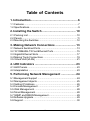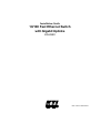
1
Installation Guide 10/100 Fast Ethernet Switch with Gigabit Uplinks KS-2240 DOC.000917-KS2240-K -1- 2000 KTI Networks Inc. All rights reserved. No part of this documentation may be reproduced in any form or by any means or used to make any directive work (such as translation or transformation) without permission from KTI Networks Inc. KTI Networks Inc. reserves the right to revise this documentation and to make changes in content from time to time without obligation on the part of KTI Networks Inc. to provide notification of such revision or change. For more information, contact: United States International KTI Networks Inc. P.O. BOX 631008 Houston, Texas 77263-1008 Phone: Fax: E-mail: URL: 713-2663891 713-2663893 [email protected] http://www.ktinet.com/ Fax: E-mail: URL: 886-2-26983873 [email protected] http://www.ktinet.com.tw/ -2- 24-Port Fast Ethernet Switch with Gigabit Uplinks INSTALLATION GUIDE DOC.000917-KS2240-NK -3- The information contained in this document is subject to change without prior notice. TRADEMARKS Ethernet is a registered trademark of Xerox Corp. This device complies with Class A Part 15 the FCC Rules. Operation is subject to the following two conditions: (1) This device may not cause harmful interference, and (2) this device must accept any interference received including the interference that may cause. CISPR A COMPLIANCE: This device complies with EMC directive of the European Community and meets or exceeds the following technical standard. EN 55022 - Limits and Methods of Measurement of Radio Interference Characteristics of Information Technology Equipment. This device complies with CISPR Class A. WARNING: This is a Class A product. In a domestic environment this product may cause radio interference in which case the user may be required to take adequate measures. CE NOTICE Marking by the symbol indicates compliance of this equipment to the EMC directive of the European Community. Such marking is indicative that this equipment meets or exceeds the following technical standards: EN 55022: Limits and Methods of Measurement of Radio Interference characteristics of Information Technology Equipment. EN 50082/1:Generic Immunity Standard -Part 1: Domestic Commercial and Light Industry. EN 60555-2: Disturbances in supply systems caused by household appliances and similar electrical equipment - Part 2: Harmonics. -4- Table of Contents 1. Introduction ......................................................... 6 1.1 Features ............................................................................... 7 1.2 Specifications ....................................................................... 9 2. Installing the Switch ......................................... 10 2.1 Packing List ....................................................................... 10 2.2 Panels ................................................................................ 11 2.3 Mounting the Switches ....................................................... 12 3. Making Network Connections ......................... 13 3.1 Network Switched Ports ..................................................... 13 3.2 10/100BASE-TX Fast Ethernet Ports .................................. 15 3.3 Gigabit Ethernet Slots ........................................................ 17 3.4 Making Trunk Connections ................................................. 19 3.5 Virtual LAN (VLAN) ............................................................ 21 4. LED Indicators .................................................. 23 4.1 LED Panels ........................................................................ 23 4.2 Interpretation ...................................................................... 23 5. Performing Network Management .................. 24 5.1 Management Support ......................................................... 24 5.2 Management objects .......................................................... 25 5.3 Setting IP Address ............................................................. 26 5.4 Console Management ........................................................ 27 5.5 Web Management .............................................................. 28 5.6 Telnet Management ............................................................ 28 5.7 SNMP and RMON Management ......................................... 29 5.8 Software Upgrade ............................................................... 29 5.9 Support .............................................................................. 30 -5- 1. Introduction Driven by recent advances in desktop computing technology, todays network applications have increased in speed, power and the ability to process information. To meet the demands of these more bandwidthintensive applications, this switch device provides significant increase in performance for your Ethernet and Fast Ethernet network. The switch comes with high number of 10/100 Fast Ethernet switched ports, each capable of transferring information simultaneously at full wire speed to control and allocate the network bandwidth. It also provides two Gigabit Ethernet slots for migration to Gigabit network smoothly. The key features of the switch units are: High Port-count and High Bandwidth : Combining large number of 10/ 100Mbps-based Fast Ethernet switched ports and two Gigabit ports, the switches deliver a tremendous aggregated bandwidth for your network. Easy Migration : With 10BASE-T, 100BASE-T, 1000BASE-X support, the switch provides a non-disruptive and smooth migration path from Ethernet to Fast Ethernet, and even to Gigabit Ethernet network. Easy Installation : With the functions of auto-speed-sensing and auto-negotiation on each port, the switches support plug-and-play installation by default which eliminates configuration problems. Network Management : With the built-in SNMP and web management software agent, the switch provides network management function for advanced applications. It allows you to control and monitor the switch remotely from anywhere in the network. -6- 1.1 Features Designed for resolving congestion problems caused by bandwidth-hungry devices and bandwidth-intensive applications as well as a high number of users, the switches not only adhere to the IEEE 802.3 10BASE-T, IEEE 802.3u 100BASE-TX, and IEEE 802.3z 1000BASE-X standards, but also feature: High port-count of 10/100BASE-TX auto-negotiation switched ports for flexible connections to desktop PCs, servers and hubs. The 10/100BASE-TX switched ports support: - auto speed sensing for 100Mbps or 10Mbps connection - auto configuration with auto-negotiation devices Two 1000Mbps Gigabit switched port slots support: - 1000BASE-SX Gigabit switched module Self learning for network configuration Store and forward switching to ensure only good packets are forwarded Full-duplex or half-duplex operation support for all switched ports Forwarding and filtering at full wire speed Supports IEEE 802.3x flow control for full-duplex operation Supports back-pressure flow control for half-duplex operation Supports IEEE 802.1d spanning tree protocol Supports port-based and 802.1q tagged VLAN Supports trunking function Supports Web-based and SNMP management Full diagnostic LED indicators to indicate the power and port status 19-inch rack mountable -7- Management Features: Telnet for remote control Provides one RS232 local console port 802.1D Bridging - 802.1d spanning tree - 802.1P/Q GARP/GVRP Routing - RIP, RIP-2, DHCP-relay, ICMP router discovery message IP Multicast - IGMP Snooping - IP Multicast packet filtering TFTP - software upgrade capability Web-based management SNMP management - SNMP agent RFC 1155-1157 - MIB-II, Bridge MIB (RFC 1286), private MIB - VLAN MIB (802.1Q) - RMON MIB (RFC 1757) -static, history, alarm, event - IGMP MIB -8- 1.2 Specifications Standard IEEE 802.3 10BASE-T, IEEE 802.3u 100BASE-TX IEEE 802.3z 1000BASE-X IEEE 802.3ad Port trunking IEEE 802.3x Full duplex flow control IEEE 802.1D Spanning tree IEEE 802.1Q Tagged VLAN IEEE 802.1P/Q GARP/GVRP Network ports 24 10/100BASE-TX switched ports 2 Gigabit switched slots for optional Gigabit module Console port 1 DB9 Male connector Cables 10BASE-T Cat. 3, 4, 5 UTP cable (100 meters max.) 100BASE-TX Cat. 5 UTP cable (100 meters max.) 1000BASE-SX Multimode fiber Unit LED Power status TP Port LED Link/Activity, Speed, Duplex/Collision status per port Filtering rate 14,880 pps for Ethernet (10BASE-T) 148.8 Kpps for Fast Ethernet (100BASE-TX) 1.488 Mpps for Gigabit ports (1000BASE-X) Forwarding rate 14,880 pps for Ethernet (10BASE-T) 148.8 Kpps for Fast Ethernet (100BASE-TX) 1.488 Mpps for Gigabit ports (1000BASE-X) Filtering address Multicast/Broadcast/Unicast address MAC addresses 12K entries RAM buffer 2MBytes for Port 1-12 and Giga-slot1 2MBytes for Port 13-24 and Giga-slot2 Environment Temperature 0oC to 40oC Relative humidity 10% to 90% non-condensing Power Universal power supply 100-240VAC, 50/60Hz, 65W -9- 2. Installing the Switch The switch is designed to operate in workgroup environments without a complicated configuration procedure. It also features an auto-select 100240V, 50/60Hz power supply unit, which works in most countries around the world. Before connecting the supplied power cord into the switch, check to see that the cord voltage and current rating conform to the standards of the country of operation. 2.1 Packing List The switch has the following components shipped with it: One switch unit One AC power cord One RS232 console cable 19-inch rack mount kit CD for installation guide, software modules, MIB file and software operation manuals -10- 2.2 Panels The following figure illustrates the major components on front and rear panels: 10/100 Port 1-12 10/100 Port 13-24 Gigabit Slot1 Gigabit Slot2 LED indicators AC power switch AC power socket Console port 10BASE-T/100BASE-TX Port #1 - #12 10BASE-T/100BASE-TX Port #13 - #24 Gigabit Slot #1 for 1000BASE-FX module series Gigabit Slot #2 for 1000BASE-FX module series LED display for power and all port status Switch to turn on or off the power to the unit Plug-in socket for AC power cord Connector for local console connection -11- 2.3 Mounting the Switches Desktop Mounting The switches can be placed on a desktop as a stand-alone unit. Allow enough ventilation space between the switch and the objects around it. Desktop Mounting Rack Mounting For mounting the switch into a 19-inch rack, a pair of mounting brackets is included in the pack. Install Rack Mount Brackets Install the switch into a 19-inch rack as illustrated in the following figure: Install the Switch into a 19-inch Rack -12- 3. Making Network Connections 3.1 Network Switched Ports The following figure illustrates the switched ports provided on the front panel. The switch comes with 24 10/100BASE-TX Fast Ethernet switched ports and two Gigabit Ethernet slots for Gigabit Ethernet modules. The following table lists the connectors provided on each network ports: Port # Port 1 Port 2 Standard 10/100BASE-TX 10/100BASE-TX 10/100BASE-TX Port 3-24 10/100BASE-TX Gigabit slot1 1000BASE-FX Gigabit slot2 1000BASE-FX Connector type MDI-X RJ-45 MDI-X RJ-45 MDI RJ-45 MDI-X RJ-45 Slot Slot -13- Mark 1X 2X 2 3X - 24X GIGABIT1 GIGABIT2 10/100BASE-TX Fast Ethernet Switched Ports Each switched port supports one connection to a LAN segments. Each segment is an independent shared network in one collision-domain. The connection can be to either a 10BASE-T or a 100BASE-TX device. MDI-X and MDI RJ-45 Connectors MDI-X jack is labeled [X] normally to indicate the jack is designed with internal crossover function. It allows a connection to an end station using straight-through UTP cable. MDI RJ-45 connector is provided for easy uplink via standard straight-through UTP to other device that supports MDI-X RJ-45 connector. The following table shows the pin assignments of MDI-X and MDI RJ-45 connector respectively: PIN# MDI-X Jacks MDI Jack 1 Rx+ Tx+ 2 RxTx3 Tx+ Rx+ 6 TxRx4,5,7,8 NC NC Gigabit Ethernet Slots Two Gigabit Ethernet slots are provided for Gigabit connections. Each can accommodate one Gigabit Ethernet module. A variety of optional modules is available for selection. Refer to section 3.3 for more information. -14- 3.2 10/100BASE-TX Fast Ethernet Ports The switch can support connections to the following devices: • • • • • 10BASE-T or 10/100BASE-TX network cards 10BASE-T hub ports 100BASE-TX hub ports 10/100BASE-TX dual speed hub ports 10/100BASE-TX switch ports Auto-negotiation Capable The ports support auto-negotiation function when establishing a link connection with any auto-negotiation capable device. The connection speed and duplex mode are determined through the negotiation process with the connected device. Auto-speed-sensing When connecting to a non-auto-negotiation device, half duplex mode is used. However, the ports can auto-detect the connection speed. Manual Configuration The ports are configured to be enabled for auto-negotiation as factory default. However, it also can be changed and stick to one of the following configurations through network management operation: 10M Half-duplex 10M Full-duplex 100M Half-duplex 100M Full-duplex Trunking Function The ports are configured as normal data ports instead of trunking ports as factory default. In order to support trunking function, any port can be configured as a trunking port manually through network management operation. As configured, it is no longer a data port. For more details about trunking, refer to section 3.4. -15- Flow Control Half-duplex mode uses back pressure flow control to prevent the receiving buffer from being overrun by data from a source node. Full-duplex mode uses the 802.3X flow control standard to prevent fast Physical Ports data traffic from overrunning slow data traffic. UTP Cable Connections When making a connection to another device using straight-through UTP cable, make sure MDI-X to MDI connection rule is followed. The following figure illustrates the pin assignments of a straight-through UTP and a crossover UTP cable: Straight-through and Crossover UTP Cable It is suggested to use straight-through UTP cables for all UTP connections. The maximum length and UTP cable categories used for the connections to a 10BASE-T device and 100BASE-TX device are: CONNECTED DEVICE UTP CABLE USED & MAXIMUM LENGTH 10BASE-T device Cat. 3, 4, 5 UTP (100 meters) 100BASE-TX device Cat. 5 UTP (100 meters) -16- 3.3 Gigabit Ethernet Slots Each Gigabit Ethernet slot can accommodate one optional Gigabit Ethernet module for your Gigabit connection. The following modules are available for selection: Module 2240-SX 2240-SXJM Wavelength Connector type Fiber cable 850nm SC Multimode fiber 850nm MT-RJ Multimode fiber Module 2240-SX 2240-SX 2240-SXJM 2240-SXJM Fiber cable used 50/125µm 62.5/125µm 50/125µm 62.5/125µm Maximum length 500 meters 220 meters 500 meters 220 meters Module Outline The following figure illustrates two examples of Gigabit modules. Different types of modules are mounted with different fiber connectors. Gigabit Ethernet Modules (Top view) Auto-negotiation function -17- The Gigabit Ethernet module supports auto-negotiation although it only operates on 1000M full-duplex mode. This function makes sure the system operates with maximum performance when it is connected to an auto-negotiation capable Gigabit Ethernet device. Duplex Mode Full duplex Fiber cable MM 50/125mm, 62.5/125mm recommended Module Installation 1. Turn off the power to the switch unit. 2. Open the cover of Gigabit slot. 3. Insert the module into slot until it is seated properly. 4. Screw the module onto the chassis securely. -18- 3.4 Making Trunk Connections Two switch units can be cascaded together through any regular switched data port on each unit when a port expansion is required. However, the transfer bandwidth between the two cascaded ports is limited to 200Mbps full duplex. To increase the bandwidth for the connection between two switch units, a trunking function is implemented on the switch unit for this purpose. Normal data ports can be configured optionally as trunking ports through the network management operation. Two or more trunking ports composes one trunk. Two switch units can be cascaded through one trunk. The aggregated bandwidth of one trunk can be up to 1.6Gbps, if 8 trunking ports are used for one trunk. Refer to the software operation manuals in the supplied CD-ROM for more information about how to configure a data port as a trunking port. The following figure illustrates an example of 4-port trunk connection between switch A and switch B. The Port 3, 4, 5 and 6 of switch A are configured as trunking ports and compose one trunk. The Port 5, 6, 7, and 8 of switch B are configured as trunking ports and compose one trunk. The aggregated bandwidth of the trunk is 800Mbps. -19- Rules : 1. One switch can be configured to have up to 4 trunks and each trunk can be composed of up to 8 trunking ports. All port members of one trunk must locate in same group, either in group [port 1-port 12] or in group [port 13 - port 24]. 2. One trunking port can only belong to one trunk. 3. Only one trunk can exist between two switch units. 4. Crossover UTP cables should be used at the same time for one trunk connection. The length of each cable can be up to 100 meters. 5. When the switched data ports are enabled as trunking ports, they can only serve trunking function, but no other data function. 6. Since the trunking is proprietary, the switches do not support trunk connection to other brands switches. The following figure illustrates a typical example of trunk connections between more than two switch units. Each trunk is a 2-port trunk. There are four trunks existing in this example. Each has 400Mbps bandwidth. The top switch is configured to have four trunks and is cascaded to four lower switch units. -20- 3.5 Virtual LAN (VLAN) Each port of the switch unit connects to one individual LAN segment. There can be many Ethernet nodes located on each segment. The switch performs network data forwarding between different LAN segments. It allows Ethernet nodes located on different segments to communicate with each other. Basically, all Ethernet nodes are in one single LAN. A Virtual LAN (VALN) is a logical, independent workgroup within a network. The member in this workgroup communicate as if they are sharing the same physical LAN segment. VLANs are not limited by the hardware constraints that physically connect traditional LAN segments to a network. As a result, VLANs can define a network into multiple logical configurations. Because VLANs are self-contained, only the devices within the same VLAN can communicate with each other. If a device in one VLAN wants to communicate with a device in another VLAN, the traffic must go through a router. This would enhance the security of the network. In addition, broadcasts from servers within each group would go to the members of its own VLAN. This ensures that broadcasts cannot cause a network meltdown due to traffic volume. Implementation The VLAN implementation of this switch allows up to 256 VLANs in one switch. By using explicit or implicit VLAN tagging and the GARP/GVRP protocol (IEEE 802.1p and 802.1Q), VLANs may span across multiple switches. A MAC address can belong to multiple VLANs, and a switched port may be associated with multiple VLANs. Static Definitions of VLAN Membership The switch defines VLAN membership based on ports. Port based VLANs are organized by physical port numbers. The definitions are configured through the supported network management console. -21- Dynamic Learning of VLAN Membership While port based VLAN only defines static binding between a VLAN and its port members, the MAC address database associated with each port number and VLAN is learned and built up dynamically by the switch at run time. Dynamic Learning of Remote VLAN In addition to adding and deleting VLAN member ports through network management console software statically, the switch also supports GVRP (GARP VLAN Registration Protocol). GVRP allows for dynamic registration of VLAN port numbers within a switch and across multiple switches. It is also used to communicate VLAN registration information to other VLAN-aware switches, so that a VLAN member can be covered by a wide range of switches in a network. GVRP allows both VLAN-aware workstations and switches to issue and revoke VLAN memberships. The switches register and propagate VLAN membership to all ports belonging to the active topology of the VLAN. VLAN Configuration The switch currently provides a Local/Remote Management Console Interface for VLAN configuration and management. An SNMP-based VLAN MIB is also provided. Combining the hardware and software functions, the switch supports Intra-VLAN Communication and Inter-VLAN Communication. -22- 4. LED Indicators 4.1 LED Panels The switch provides comprehensive LED indicators for diagnosing and monitoring the operation of the unit as illustrated below: 4.2 Interpretation Power LED : indicates the status of the power supplied to the switch. Link/Act. LED : indicates the port cable link and traffic activity. Speed LED : indicates the connection speed used Duplex/Col. LED : indicate the duplex mode used and collision status The LED indicators labeled a port number on top are corresponding to a specific 10/100BASE-TX port. The LED indicators labeled with G1 and G2 are corresponding to the Gigabit slot 1 and slot 2 respectively. The states and indications are: LED STATE Power Off Power On Link/Act. On Link/Act. Off Link/Act. Blink Speed On Speed Off Duplex/Col. On Duplex/Col. Off Duplex/Col. Blink INDICATION No power is supplied to the device. Power is supplied to the device. An active link is established. No active link is established. There are Tx or Rx activities. 100Mbps speed is used. 10Mbps speed is used. Full duplex mode is used. Half duplex mode is used. Collision occurrences -23- 5. Performing Network Management 5.1 Management Support The switch is featured with management functions and can be managed by using the following methods: _ Direct console connection over an RS232 cable _ Web browser software from Internet or Intranet over TCP/IP network _ Telnet software over TCP/IP network _ SNMP manager software over TCP/IP network The following figure illustrates a management model diagram: -24- 5.2 Management objects The following table lists the management objects supported by the system: Login Basic Management Activities _ General Management Configuration - system parameters _ LAN Port Configuration - speed, link type, duplex, flow control _ Console Port Configuration - console baud rate, flow control, modem control Advanced Management Activities _ Switching Database Configuration VLAN Perspective - edit VLAN configuration - edit VLAN port membership and tagging settings - VLAN activities IP Multicast Group Perspective MAC Address Perspective - characteristics associated with a MAC address Port Perspective - per port VLAN activities - per port statistics _ IP Networking IP and RIP Settings ARP Table Settings Routing Table DHCP Gateway Settings Ping Settings _ Viewing IP Network Parameters _ _ _ _ Bridging Static Filtering Spanning Tree Functions SNMP Functions - SNMP related configuration -25- _ _ _ _ Other Protocols - GVRP, IGMP Port Trunking Port Mirroring File transfer - software upgrade Logout Save settings Restore default settings Reboot 5.3 Setting IP Address Before performing any management operation over network, the most important thing is to learn the detailed information about the TCP/IP network where the managed unit is located. The information includes the network address, subnet mask, broadcast IP, IP of the default router. The second thing is to assign an IP address to the managed unit when it is received for the installation. A unique IP address is used to identify each managed device from others. No factory default IP address is assigned. Assign a unique IP address to the managed switch using direct console management before performing any in-band management operation. When you log on to the switch console port for the first time, a sign-on string appears and you are prompted for a console login name and password. The factory default login name is admin and password is 123456. If you desire, you can change this password after you log on. -26- 5.4 Console Management Any PC running Windows 95/98/ or NT can be used as a console. Use the supplied RS232 cable and connect the console port to the COM port of your console PC. Use Windows Hyper Terminal program to perform this out-of-band management operations. Factory default settings of the Console port Baud rate : 115200, N, 8, 1, 1 Flow control : disabled Modem control : disabled The console interface consists of a series of menu boxes. Each menu box has several options, which are listed vertically. A highlight in each box lets you select the option you wish to choose; pressing the Enter key activates the highlighted option. Navigating Through the Console Interface To Move the highlight one line up in a menu box. Move the highlight one line down in a menu box. Move the highlight between screens. Select the highlighted option. Move to the previous menu. Press This Key K or Up arrow J or Down arrow Tab Enter Escape Refer to the operation manual provided in the supplied CD-ROM for the details. -27- Use the supplied RS232 cable to make the console connection directly from a PC COM port. The pin assignments of the connection are: Switch DTE console port 9-pin PC COM port Pin1 DCD -------------------------------- Pin1 2 RXD -------------------------------3 3 TXD -------------------------------2 4 DTR -------------------------------6 5 GND -------------------------------5 6 DSR -------------------------------4 7 RTS -------------------------------8 8 CTS -------------------------------7 9 RI -------------------------------9 5.5 Web Management Use any web browser with JAVA script support like Netscape Communicator 4.x or Microsoft Internet Explorer 4.0 or later on any platform. Connect to the managed unit using the IP address as URL address. http://xxx.xxx.xxx.xxx 5.6 Telnet Management Use Telnet software to perform the management operation. The most convenient solution is using the built-in Telnet function in a Windows 95/98/ or NT PC. Enter into DOS window and invoke telnet command : >telnet xxx.xxx.xxx.xxx to connect to the managed switch. The specified xxx.xxx.xxx.xxx is the IP address of the managed switch. -28- 5.7 SNMP and RMON Management SNMP management and RMON activities are performed at a network management station running SNMP network management application manager software with graphical user interface. The switch serves as an SNMP agent and provides RMON capabilities that allows network administrators to set parameters and view statistical counters defined in the MIB-II, Bridge MIB, private MIB and RMON MIB. The supported MIBs are available in the supplied CD-ROM of the switch. Use the SNMP management application software to compile the MIB file first before performing any management operation. 5.8 Software Upgrade The device supports a Software Upgrade feature through TFTP protocol and Kermit protocol. TFTP file transfer functions allow you to perform software upgrade over network and Kermit file transfer functions allow you to perform software upgrade via console port. If you select File transfer command from the Advanced Management screen, specify the following information for software upgrade operation: File name : file name of the new software version IP address : from where the software upgrade will be obtained. The address consists of numbers separated by periods. For example: 129.32.0.11 After you finish the upgrade operation, reboot the switch using the supported command within the console or telnet. -29- Note: The TFTP protocol is used to download updated software to the switch. A VLAN with the proper IP address and routing path to the TFTP server must be configured for the switch to access the specified TFTP server. TFTP is an embedded function supported in the DOS window of any Windows NT system. Contact your dealer for any new available software version. 5.9 Support This guide covers the basic information about the management functions supported by the managed switch. The detailed operation guides for all management functions are available in the software operation manual in the supplied CD-ROM. However, more features may be included into future new software upgrade. Contact the dealer where you purchased the switch for the availability of new software and/or technical support. -30-