1
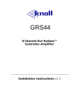
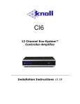
Q450rs Multiroom made easy! v 1.0 1 Important Safety Instructions: 1) Read these instructions. 2) Keep these instructions. 3) Read all warnings. 4) Follow all instructions. 5) Do not use this apparatus near water. 6) Clean only with dry cloth. 7) Do not block any ventilation openings. Install in accordance with the manufacturer’s instructions. 8) Do not install near any heat sources such as radiators, heat registers, stoves, or other apparatus (including amplifiers) that produce heat. 9) Do not defeat the safety purpose of the polarized or groundingtype plug. A polarized plug has two blades with one wider than the other. A grounding type plug has two blades and a third grounding prong. The wide blade or the third prongs are provided for your safety. If the provided plug does not fit into your outlet, consult an electrician for replacement of the obsolete outlet. 10) Protect the power cord from being walked on or pinched particularly at plugs, convenience receptacles, and the point where they exit from the apparatus. 11) Only use attachments/accessories specified by the manufacturer. 12) Use only with the cart, stand, tripod, bracket, or table specified by the manufacturer, or sold with the apparatus. When a cart is used, be careful to avoid injury from tip over. 13) Unplug this apparatus during lightning storms or when unused for long periods of time. 14) Refer all servicing to qualified service personnel. Servicing is required when the apparatus is damaged in any way. Examples include power-supply cord or plug is broken, liquid has been spilled or objects have fallen into the apparatus, the apparatus has been exposed to rain or moisture, does not operate normally, or has been dropped. 15).Under no circumstances should the output terminals of the amplifier be short-circuited. 16).Be sure that the loudspeakers connected can handle the output power of the amplifier at the loudspeakers rated impedance. The warranty on the amplifier does not cover damage to loudspeakers that have inadequate power handling capabilities. 17) Where an all-pole MAINS SWITCH is used as the disconnect device, the location on the apparatus and the function of the switch shall be described, and the switch shall remain readily operable. CAUTION: These servicing instructions are for use by qualified service personnel only. To reduce the risk of electric shock, do not perform any servicing other than that contained in the operating instructions unless you are qualified to do so. Note: Where the mains plug or an appliance cover is used as the disconnect devise, the disconnect device shall remain readily operable. WARNING: This product may contain chemicals, including lead, known to the State of California to cause birth defects or other reproductive harm. Wash hands after handling. Made in Canada/Fabrique au Canada FCC Warning Note: This equipment has been tested and found to comply with the limits for a Class B digital device, pursuant to part 15 of the FCC Rules. These limits are designed to provide reasonable protection against harmful interference in a residential installation. This equipment generates, uses and can radiate radio frequency energy and, if not installed and used in accordance with the instructions, may cause harmful interference to radio communications. However, there is no guarantee that interference will not occur in a particular installation. If this equipment does cause harmful interference to radio or television reception, which can be determined by turning the equipment off and on, the user is encouraged to try to correct the interference by one or more of the following measures: • Reorient or relocate the receiving antenna. • Increase the separation between the equipment and receiver. • Connect the equipment into an outlet on a circuit different from that to which the receiver is connected. Consult the dealer or an experienced radio/TV technician for help. Canada This Class B digital apparatus complies with Canadian ICES003. Cet appareil numérique de la classe B est conforme à la norme NMB-003 du Canada. Caution: To reduce the risk of electrical shock, do not remove the cover (or back). No user serviceable parts inside. Refer to qualified service personnel. Warning: To reduce the risk of fire or electric shock, do not expose this appliance to rain or moisture. The lightning flash with arrowhead, within an equilateral triangle, is intended to alert the user to the presence of uninsulated “dangerous voltage” within the products that may be of sufficient magnitude to constitute a risk of electrical shock to persons. The exclamation point within an equilateral triangle is intended to alert the user to the presence of important operation maintenance (servicing) instructions in the literature accompanying the appliance. Knoll Systems 14-7163 Vantage Way Delta BC V4G 1N1, Canada 145 Tyee Drive, Point Roberts, WA 98281 USA Tel: (604) 940-9326; Fax (855) 734-3363 www.knollsystems.com 2 Important Considerations Table of Contents Safety and FCC warning Amplifier checklist Important considerations What is it and who is it for Getting to know the Q450rs Q450rs system layout MR44 keypad BIX and BIB balanced input plates System specifications Wire terminations Q450rs expanding capabilities Installation procedure Troubleshooting Warranty Information 2 3 3 4 5 6 7 8 8 9 10 11 12 12 Unpacking: The carton and packing materials used in shipping your new amplifier are designed to protect it from shock and vibration during shipping. We suggest that you save the carton and packing materials to use if you move, or if the unit ever needs to be returned to us for any reason. Installation Checklist Plan your installation. Consider what sources will be used and make provisions for infrared and sources, speakers and cabling. Collect the proper tools. Run all wires and label both ends. Install speakers as directed by speaker manufacturer. Test wire for short circuits. Terminate cat5 and test for short circuits and polarity for MR44 and BIX/BIB modules. Retest. Mount Q450rs if necessary. Test speaker wire for shorts and correct impedance with ohm meter. Connect speakers. Note which zone is for which room and which source is from which location. Connect cat5 connectors. Ensure cat5 keypads and sources are going to the correct socket. Connect audio outputs to Q450rs or to ‘local’ BIX/BIB inputs. Make a note of which input is used for each source. Test all installed cabling before connecting to the Q450rs. Test the speaker and wires with a multi-meter set to ohms for correct impedance and short circuits. Resistance and impedance differ slightly so a very accurate reading is not expected. Long speaker wires will increase resistance. This also includes cat5 connectors. Incorrect polarity of a twisted pair can cause serious damage to the Q450rs and its peripherals. Do not make any wire connections of any kind with the power supply connected. During operation, the amplifier may become warm. This is normal; there are instances during highlevel playback into low impedance speakers when the amplifier will become much warmer than usual. To ensure the amplifiers trouble-free operation, it is necessary to provide adequate ventilation. Keep the amplifier away from external sources of heat such as radiators and hot-air ducts. Never place the amplifier with other heat-producing components in a cabinet or enclosure lacking free airflow. Do not stack other components on top of your Q450rs. Care, maintenance, and cleaning: wipe with clean, dry, soft cloth. If necessary, first wipe the surface with a slightly dampened soft cloth with mild soapy water, then with a fresh cloth dampened with clean water. Wipe dry immediately with a dry cloth. NEVER use benzene, thinner, alcohol, or any other volatile cleaning agent. Do not use abrasive cleaners, as they will damage the finish of the metal parts. Avoid spraying insecticides, waxes, polishing agents, or any aerosol product near the Q450 or any of its components. It is best to run extra cat5 wires to each room as this will make the installation more future proof and offers an inexpensive repair if a cable is damaged. It is important to know where the various wires required to operate the Q450rs will be run. Never run a cat5 or speaker cable parallel to a high voltage AC mains cable. This may cause problems with the operation of Q450rs. If possible don’t locate a keypad next to a light switch for the same reason. The Q450rs needs to be a safe distance from any large AC motors, including an air conditioner, or fridge/freezer, or breaker panels as this can cause unwanted interference. 3 WHAT IS IT? WHO IS IT FOR? The Q450rs is a four source, four-zone multi-room controller amplifier in a small, efficient package. It is much like having four integrated hifi amplifiers hidden away from sight and connected together for a seamless listening experience. It is equally comfortable at home as it is scaled up, using the controlled audio outputs, for larger installations such as art galleries or coffee shops. BIX Remote Input Wall Plate The Q450rs is controlled by RS232 commands. There is also a wall plate keypad controlled version available, model Q450. The balanced input wall plates (BIX) are a feature we are very proud of and we hope you will agree. The BIX plate allows the Q450 to have an input from a room or space far away from the Q450 without any drop in signal quality and best of all without any added unwanted hum and noise. This is an industry first. Let’s put this another way. Say you are enjoying a dip in the tub. Wouldn’t it be nice to be able to plug in your iPod beside the tub and not have to run to the amp to change a playlist? Best of all, the floor stays dry! Cat5 is a very reliable wire. The BIX and BIB remote input wall plates use a home run of cat5 wire. We use cat5 connectors terminated to the T568A protocol. It is strongly recommended to adhere to this standard. Speaker Connectors: We use a detachable connector sometimes called a phoenix connector. There are four connectors included with the Q450rs. Each connects one stereo zone. Coming soon is a Bluetooth balanced input plate (BIB). Not only does it allow for a wireless Bluetooth connection, there is also a wired 3.5mm audio input jack. The Q450rs is controlled with its RS232 port. This port can be connected directly to a whole house control system or with third party adapters to the home Ethernet or wifi and controlled by iPad, iPhone, android tablets and other devices. Each of the four zones can access any of the four sources, adjust volume, bass, treble, mute, and power on/off. 4 Line Inputs Controlled Outputs Direct, non-balanced RCA inputs. We do not suggest connecting a line input and a balanced input(BIB) on the same input. It is acceptable to have (for example) a direct input on 1 and 2 and balanced inputs on 3 and 4. The line level controlled outputs the same content as the amplified outputs but at lower level that can feed larger and/or multiple amplifiers. They can be connected to subwoofers too! Power Indicator Power Jack 24 VDC Center pin positive GETTING TO KNOW THE Q450rs 333mm 89mm 53mm Amplifier Outputs Balanced Zone Inputs The Q450rs is rated at 25 watts This feature is unique to the RMS per channel (50 watts Q450rs. It allows the user to per zone). connect a local source in a distant room. This is a lot of power to drive even the most demanding By being balanced, the signal speakers. quality is perfectly transmitted without any unwanted added hum or noise. Note: It is perfectly acceptable to have more than one pair of speakers per zone. Make sure the series or parallel impedance is between 4-16 ohms. RS232 Connector Note: The source inputs are shared throughout so any or all zones can play the same program material (or obviously some other input source). Note: Each zone is effectively an integrated stereo amplifier. You can use the internal stereo amplifiers and/or connect the Q450rs to larger amplifiers to increase power output or to scale up the zone to larger sub-zones. Each zone functions identically; respective to its address. 5 This configuration shows a laptop connected to the RS232 port to control the Q450rs. A BIX balanced input wall plate is shown connected to input #1. The speakers are shown connected to the Q450rs amp #1 outputs. Before trim out (or final installation) always doublecheck the wires for continuity and short circuits as problems can arise such as a tradesperson driving a screw through the wire. We suggest using a cat5 tester and investing in top quality crimp tools as second-rate or poor crimping is the number one source of installation problems. Q450rs TYPICAL SYSTEM LAYOUT Typical Installation with four zones, each connected to a pair of speakers. Zone 1 also has a BIB balanced input plate. Zone 2: Den Zone 3: Bedroom Zone 1: Hot tub Speaker Selecting input 1 from any zone will allow that zone to monitor the hot tub input source Zone 4: Kitchen 6 RS232 Connection The RS232 connection is used to control the Q450RS by an external controller or computer and can work with our without keypads. The Q450RS connects to the RS232 controller with a 9-pin db9 connector. The programming reference follows. Write Request Examples: Function Command Turn Channel On (1on) Select Input (1sl4) Set Volume (1vl50) turns on amplifier channel 1 on turn amplifier channel 1 to input 4 turn amplifier channel 1 to volume 50 (of 87) Terminal Settings To control the Q450RS amplifier via other control systems, connect a RS-232 cable to the serial control connector on the rear of the Q450RS and set your computer’s or control unit port settings to match the following configuration: Response Supported Command Summary # = numerical zone or amplifier channel value $$ = second numerical value (may be one or two digits) Setting Value Bits per second Data bits Parity Stop bits Flow control Emulation 19,200 8 None 1 None Auto detect Function Command Summary All commands are enclosed in parentheses. The request can be in some cases a read request (followed by a “?”), or a write request (followed by 0-2 ASCII digits). A read command will return the current setting, and write command will change the setting. Read request format: (nAA?) where: ( starts the command n denotes amplifier channel (if required) AA denotes the command (may be 1 or 2 letters) ? denotes the read request ) ends the command Read Request Example: Function Command Volume (1vl?) Response returns the volume on channel 1 (0-87) Write request format (nAA$$) where: ( starts the command n denotes the amplifier channel (if required) AA denotes the command (may be 1, 2 or 3 letters ) $$ denotes the value to be written if required (leading zero’s ARE necessary) ) ends the command Command Range Read/Write Remarks Version (vr?) none read only Reset (rx) none write only 1 second Channel On (#on) 1-4 write only Channel Off (#of) 1-4 write only Mute (#mu) 1-4 write only Un-mute (#um) 1-4 write only Mute All (amu) none write only Un-mute All (aum) none write only Volume Request (#vl?) 1-4 read only Volume Set (#vl$$) 1-4 / 0-87 write only Volume All (avl$$) 0-87 write only Input Request (#sl?) 1-4 read only Input Set (#sl$) 1-4 / 1-4 write only Input Select All (asl$) 1-4 write only All Channels On (aon) none write only All Channels Off (aof) none write only All Channels Vol up (avlu) none write only Note 1 All Channels Vol dn (avld) none write only Note 1 Channel Vol up (#vlu) 1-4 write only Note 1 Channel Vol down (#vld) 1-4 write only Note 1 Bass adjustment (#b$) 1-4 / 0-F write only Note 2 Treble adjustment (#t$) 1-4 / 0-F write only Note 2 Display treble (#b?) 1-4 read only Display bass (#t?) 1-4 read only Note1: Volume up or down requests increase or decrease volume level by 5 Note 2: Treble and bass commands use hexadecimal values 0-F, default (flat) is 8. Also, it is best to leave about a ½ second between commands, as some integrators may miss commands if they are entered too quickly. All commands also send a message back to the terminal after they have been completed, so that it is easy to keep track of the previous commands that were sent. 7 Note: Some commands are read or write only and some are both. For example “Mute All” is a write only command and “Version” is a read only command. Supported Command Messages Function Version Reset Channel On Channel Off Mute Un-mute Mute All Un-mute All Volume Request Volume Set Volume All Command Message (vr?) (rx) (#on) (#of) (#mu) (#um) (amu) (aum) (#vl?) (#vl$$) (avl$$) Version Number “Resetting...” “Zone # on” “Zone # off“ “Zone # muted” “Zone # unmuted” "All channels muted" "All channels un-muted" "Zone # volume level = $$" "Zone # volume level set" "All volume levels successfully changed" Input Set (#sl$) "Zone # input set" Input Request (#sl?) "Zone # is currently using input channel $” Input Select All (asl$) "All zones set to source $" All Channels Off (aof) "All zones turned off" All Channels On (aon) “All zones turned on” All Channels Vol up (avlu) “All zones volume levels increased” All Channels Vol dn (avld) “All zones volume levels decreased” Channel Vol up (#vlu) “Zone # volume increased” Channel Vol down (#vld) “Zone # volume decreased” Bass adjustment (#b$) “Bass successfully set to $” Treble adjustment (#t$) “Treble successfully set to $” BIB AND BIX INPUT WALL PLATES The BIX is an input module for sources in distant rooms or locations. To the zone it’s in, it would be ‘Local’. For this reason we identify it as such, think of it as stage left for custom installation. It’s a feature unique to Q450. It provides a differential balanced input to allow transmission of an analog signal over long distances without generating noise or signal loss due to conductor impedance. BIX is an acronym for Balanced Input eXtender. Enough with the fancy talk. It makes your iPod sound good even though it’s far from the Q450 amp. It’s a clever solution to a perennial problem faced in distributed audio systems. We just decided that it’s too important to not have integrated into the system. You can connect any audio source as long as your connecting cable has a 3.5mm (1/8th”) termination or an adaptor on the other end. This includes, but isn’t limited to, CD players, media servers, tuners, feature phones, smartphones, iPods, laptops, desktop computers, tablets, mp3 players, Bluetooth receivers, etc. Message Examples e will use the example commands from before, and show what the responses are. Function Command Response Reply On/Off Select Input Set Volume Set Bass (1on) (1sl3) (1vl50) (1baf) Set Treble (2ta) Increase Volume (2vlu) Zone 1 on Zone 1 input 3 set Zone 1 volume level = 50 Zone 1 Bass successfully set to 15 Zone 2 Treble successfully set to 10 Zone 2 volume increased BIB INPUT PLATE WITH BLUETOOTH The BIB is almost identical to the BIX above with added Bluetooth capability. Bluetooth is normally on and connected. When a jack is plugged into the AUDIO IN port Bluetooth is disabled and the signal from the 3.5mm jack is sent on the balanced line to the Q450 amplifier. BIB is an acronym for Balanced Input Bluetooth. 8 Correct polarity connections are important to maintain proper speaker phasing. When speaker phasing is correct, all speakers move in and out at the same time preserving the imaging and bass response of the program material. System Specifications Inputs Direct Inputs Balanced Inputs Control Infrared 4 gold stereo RCA 4 RJ45 from BIX or BIB 1 RS232 nine pin port Not implemented Outputs Stereo amplifiers Direct Outputs 4 x 50 watts 4-16 ohms 4 controlled gold stereo RCA System Frequency Response Operating Temp. Dimensions Weight Power 20 Hz to 20 kHz -20°C to 45°C ( 89 x 53 x 333 mm (3.5 x 2 x 13.2ʺ) 820 g (1.81 lbs.) DC 24 V center pin + 100-240 VAC 50-60 Hz Run the wires to speaker locations. Do not coil any excess cable, as this may become an inductor that creates frequency response variations in your system. Lastly, connect the wires to the speakers, again being aware of proper polarity. Remember to connect the negative or black wire, to the matching terminal on the speaker. The positive or red wire should be connected to the matching terminal on the speaker. After powering up the system, check the speakers to verify that they are operating properly. R+ R- L- L+ SPEAKER TERMINATION To ensure that the high quality signals produced by your amplifier are carried to your speakers without loss of clarity or resolution, Knoll advises that you use high-quality speaker wire. Many brands of wire are available — the choice may be influenced by the distance between your speakers and the amplifier, the type of speakers you use, personal preferences, along with other factors. For safety reasons, if any wires are placed inside walls or ceilings, they may be required to be fire rated. Always check with local building officials. Regardless of the brand or type of speaker wire chosen, we suggest that you use a wire constructed of multi-strand copper with a gauge of 16 or less (the lower the number, the thicker the cable). 16 gauge wire may be used for runs up to 33’ (10 m). 14 -12 gauge wire is recommended for longer runs. We do not recommend that you use any wires with an AWG equivalent of 18 or higher due to the power loss and degradation in performance. Note: While most speaker manufacturers follow industry convention of using red terminals for positive connections and black terminals for negative, some manufacturers may vary from this configuration. To ensure proper phase connections and optimal performance, consult the identification plate on our speaker terminals, or the speaker’s manual to verify polarity. Contact the speaker’s manufacturer if you do not know the polarity of your speakers. A detachable plug is provided for each stereo channel output. Strip approximately ¼” (6 mm) of insulation from the end of each speaker wire and carefully twist the strands of each conductor together. Be sure not to cut the individual strands or twist them off. All strands must be used for optimal performance. Insert the wire into the plug and screw the screws very tight. Inspect that there are no stray wire “hairs” that can short circuit in the plug. Pin 8 8 - BROWN - REDUNDANT TIA/EIA - T568A 7 - WHITE/BROWN - REDUNDANT 6 - ORANGE - INFRARED 5 - WHITE/BLUE - COMMON / GOUND / EARTH 4 - BLUE - DC +12V 3 - ORANGE/WHITE - REDUNDANT 2 - GREEN - SYSTEM DATA 1 - WHITE/GREEN - SYSTEM CLOCK Pin 1 Cat 5/RJ45 Termination 9 EXPANDING CAPABILITIES exact same way as the Q450rs integrated amplifiers do. The Q450rs sports some unique features that This will allow for fine tuning the output volume of your sub zone so there aren’t spots that are too loud or too quiet. provide for larger and more sophisticated installations. To control any amplifier a larger zone will require additional equipment. This is an example that will allow the Q450rs’s flexibility to cater to larger spaces like bars, coffee shops and large zones like open design. Usually these are living room, dining room and kitchens. In a coffee shop, the kitchen staff can listen to different program material than the customers, for example. In bars, TV’s can have their own zones while customers playing pool can listen to music. An external amplifier or amplifiers can be used to extend a zone’s size. The layout below shows two 12 channel KES600 amplifiers (50 watts per channel) powering up to 12 pairs of speakers, significantly increasing the driving capability of this system. We recommend an amplifier that will allow you to adjust the individual outputs like the KES600. Note that these sub zones are receiving the identical input that the Q450rs internal amp receives. The source, bass, treble and mute functions will behave in the In this example, zone one has one speaker pair connected to the Q450rs. Zone 2 is the same. Zone 3 is connected to seven pairs of speakers. One pair is being driven directly from the Q450rs and the other 6 pairs by the lower KES600. The zone 3 total output power is 650 watts. Zone 4 is also connected to seven pairs of speakers. One pair is being driven directly from the Q450rs and the other 6 pairs by the upper KES600. The zone 4 total output power is 650 watts. As you can see, the Q450rs is very versatile. AM/FM TUNER 10 INSTALLATION INSTALLATION PROCEDURE Tools You Will Need Installing the Q450rs is intended to be a relatively easy procedure with no programming required. These tools are specific to Q450rs and more may be required depending on speakers and peripherals used. Part One - Planning A small flat head screw driver with a blade that is about 3.5mm (1/4”) is ideal. This is for terminating the speakers into the Q450rs speaker or Phoenix connector. Too big won’t fit in the opening, too small won’t allow for enough torque for a good seating of the speaker wire. Before installing we recommend you make an installation plan. This involves deciding where the speakers will go, and if you’re intending to, where to place the local zone inputs, or BIX as we call them and of course the various music sources. There are up to four pairs of speaker wire (one pair per zone) and up to four cat5 for the BIX/BIB’s. Wire Strippers Part Two - Prewire Suitable for stripping speaker wire. Prewiring is a very important step. The effort you put into planning should make this step easier. When running wire, leave an extra 1m (3’) on both ends. Terminate all Cat5 wires with RJ45 connectors. Screwdriver Multi-meter or Impedance Meter This is required to avoid damage to Q450rs and the speakers and will save much time and frustration should a speaker wire be damaged during installation. Do it. Cat5/RJ45 Crimper Tool This must be top quality. The ‘Ideal’ by ‘Telemaster’ is a very good choice. Most calls to tech support are a result of poor connections caused by an inferior crimper tool used for cat5 termination. Cat5 Tester Until we figure out how to see electricity, we need a way to ensure that it’s being transported correctly. A cat5 tester that shows that not only continuity of the wire, but shows that they are going to the correct pins. This is very useful and highly recommended. Labeling Medium Some method to identify the different cables from one another and apart from other systems/networks. During installation other trades people can move or even remove the ends of long wires. Two labels on both ends can offer a little redundancy. Note: It is important you know where you’ll run the various wires required operate Q450rs. You cannot run a cat5 or speaker cable parallel to a high voltage AC mains cable. This may cause problems with the operation of Q450rs. Q450rs needs to be a safe distance, about 1m (3’) from any large AC motors, like in an air conditioner or fridge/freezer, or breaker panels. Part Three – Installation or Trim Out You should now install the speakers and install the wires in them. Take care to ensure the speaker wire polarity is correct (in phase), the wire is neat and no wire fibers are outside the connectors. At the Q450rs terminate the speaker wires with the supplied connector. Check each speaker circuit for shorts and proper impedances. Take extra care at this step to ensure your twisted pairs are correctly routed and that the phasing is correct. A fault here can seriously damage Q450rs and its peripherals. Check this three times! Mount the Q450rs. Plug in all connectors except for the powers supply unit (PSU). Double check that the connectors are routed to the correct Q450rs terminals. Plug in a known working audio source directly to Q450rs. Preferably, use a source input that is not being used for a BIX. Plug in the Q450rs power supply. Check Q450rs to see that the power LED is illuminated. Press play on your known working audio source and head to your closest zone. Select the audio source on your control device you activated in previous step. Turn up volume and listen for signal. Check signal for distortion or clipping. Move to next zone, rinse, repeat until all zones are active. Bring a known working audio source to BIX locations to test for signal. After completing this test, perform the same test on BIX/BIB in other zones. Grab a soda and pat yourself on the back. Throw on a tune and enjoy your hard work. 11 TROUBLESHOOTING No Q450rs Power 1. 2. 3. Observe LED on Q450rs is on. Check to see if Q450rs is plugged in. Test AC outlet with a lamp to see if it is active. Q450rs led on but no sound 1. 2. 3. 4. Ensure the source input is connected to the input selected and the source is playing. If a BIX or BIB balanced input plate is being used, inspect and if necessary test the cat5 cable with a cat5 tester. If the cable tests correctly try connecting the source directly to the corresponding Stereo source input on the Q450rs. If it works then something is wrong with the BIX/BIB plate or its wiring. Make sure the controlling devise is properly installed with the correct app and hardware. Sound is distorted 1. 2. 3. 4. Try turning down the sound source volume (example: iPod) and turning up the Q450rs volume. Turn down zone volume. Check the speaker impedance with a multimeter to make sure it is not short circuited or partially short circuited. Check speakers for damage or for loose material in cavity. LIMITED WARRANTY Knoll Systems (“Knoll”) warrants that each Q450rs (“the Product”) sold hereunder will conform to and function in accordance with the written specifications of Knoll. Said limited warranty shall apply only to the first person or entity that purchases the Product for personal or business use and not for the purpose of distribution or resale. Said warranty shall continue for a period of three years from the date of such purchase. Accessories such as remote control, keypads and balanced input plates when sold with or without Knoll amplifiers or controller amplifiers have a warranty that shall continue for a period of one year from the date of such purchase. Knoll does not warrant that the Product will meet the specific requirements of the first person or entity that purchases the Product for personal or business use. Knoll’s liability for the breach of the foregoing limited warranty is limited to the repair or replacement of the Product or refund of the purchase price of the Product, at Knoll’s sole option. Replacement Product may be re-furbished in “like-new” condition, at Knoll’s sole discretion. To exercise the Purchaser’s rights under the foregoing warranty, the Product must be returned at the Purchaser’s sole cost and expense, to Knoll or to any authorized Knoll service center provided, and the Product must be accompanied by a written letter explaining the problem and which includes (i) proof of date of purchase; (ii) the dealer’s name; and (iii) the model and serial number of the Product. When sending your unit in for repair, please ship your unit in its original packing material or a Knoll approved ATA Shipping Case, or have a professional packaging company pack the unit. Please insure your shipment for its full value. A return authorization number, issued by the Knoll customer service department, must also be clearly displayed on the outside of the shipping carton containing the Product. Note: Remanufactured Products are exempt from the foregoing Limited Warranty. Please refer to the Remanufactured Product Warranty for applicable warranty information. WARRANTY LIMITATION AND EXCLUSION Knoll shall have no further obligation under the foregoing limited warranty if the Product has been damaged due to abuse, misuse, neglect, accident, unusual physical or electrical stress, unauthorized modifications, tampering, alterations, or service other than by Knoll or its authorized agents, causes other than from ordinary use or failure to properly use the Product in the application for which said Product is intended. DISCLAIMER OF UNSTATED WARRANTIES THE WARRANTY PRINTED ABOVE IS THE ONLY WARRANTY APPLICABLE TO THIS PURCHASE. ALL OTHER WARRANTIES, EXPRESS OR IMPLIED, INCLUDING, BUT NOT LIMITED TO, THE IMPLIED WARRANTIES OF MERCHANTABILITY AND FITNESS FOR A PARTICULAR PURPOSE ARE DISCLAIMED. THERE ARE NO WARRANTIES THAT EXTEND BEYOND THE FACE HEREOF AND THE FOREGOING WARRANTY SHALL NOT BE EXTENDED, ALTERED OR VARIED EXCEPT BY WRITTEN INSTRUMENT SIGNED BY KNOLL. SOME STATES DO NOT ALLOW LIMITATIONS ON HOW LONG AN IMPLIED WARRANTY MAY LAST, SO SUCH LIMITATIONS MAY NOT APPLY TO YOU. LIMITATION OF LIABILITY IT IS UNDERSTOOD AND AGREED THAT KNOLL’S LIABILITY WHETHER IN CONTRACT, IN TORT, UNDER ANY WARRANTY, IN NEGLIGENCE OR OTHERWISE SHALL NOT EXCEED THE RETURN OF THE AMOUNT OF THE PURCHASE PRICE PAID BY PURCHASER AND UNDER NO CIRCUMSTANCES SHALL KNOLL BE LIABLE FOR SPECIAL, INDIRECT, INCIDENTAL OR CONSEQUENTIAL DAMAGES OR LOST PROFITS, LOST REVENUES OR LOST SAVINGS. THE PRICE STATED FOR THE PRODUCT IS A CONSIDERATION IN LIMITING KNOLL’S LIABILITY. NO ACTION, REGARDLESS OF FORM, ARISING OUT OF THE AGREEMENT TO PURCHASE THE PRODUCT MAY BE BROUGHT BY PURCHASER MORE THAN ONE YEAR AFTER THE CAUSE OF ACTION HAS ACCRUED. SOME STATES DO NOT ALLOW THE EXCLUSION OR LIMITATION OF INCIDENTAL OR CONSEQUENTIAL DAMAGES SO THE ABOVE LIMITATION OR EXCLUSION MAY NOT APPLY TO YOU. THIS LIMITED WARRANTY GIVES YOU SPECIFIC LEGAL RIGHTS, AND YOU MAY ALSO HAVE OTHER RIGHTS WHICH VARY FROM STATE-TO-STATE. 12