1
INSTRUCTION MANUAL
144 MHz FM TRANSCEIVER
TH-K20A
TH-K20E
430 MHz FM TRANSCEIVER
TH-K40A
TH-K40E
NOTIFICATION
This equipment complies with the essential requirements of
Directive 1999/5/EC.
The use of the warning symbol
means the equipment is subject
to restrictions of use in certain countries.
This equipment requires a licence and is intended for use in the
countries as below.
AT
IE
SE
LT
BE
IT
CH
MT
DK
LI
GB
PL
FI
LU
CY
SK
FR
NL
CZ
SI
DE
NO
EE
BG
GR
PT
HU
RO
IS
ES
LV
ISO3166
© B62-2365-00 (K, E, M)
09 08 07 06 05 04 03 02 01 00
THANK YOU
We are grateful you decided to purchase this KENWOOD FM transceiver.
KENWOOD always provides Amateur Radio products which surprise and excite
serious hobbyists. This transceiver is no exception. KENWOOD believes that
this product will satisfy your requirements for voice communication.
MARKET TYPE CODES
K: The Americas
E: Europe
M: General
The market type code is printed on the bar-code label of the carton box.
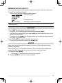
WRITING CONVENTIONS FOLLOWED IN THIS MANUAL
The writing conventions described below have been followed to simplify
instructions and avoid unnecessary repetition.
Instruction
Action
Press [KEY].
Momentarily press KEY.
Press [KEY] (1s).
Press and hold KEY for 1 second or longer.
Press [KEY1], [KEY2].
Press KEY1 momentarily, release KEY1, then press
KEY2.
Press [F] - [KEY].
Press the F key to enter Function mode, then press
KEY to access its secondary function.
Press [KEY] + Power ON.
With the transceiver power OFF, press and hold
KEY while turning the transceiver power ON.
Information on Disposal of Old Electrical and Electronic Equipment and Batteries (applicable for EU
countries that have adopted separate waste collection systems)
Products and batteries with the symbol (crossed-out wheeled bin) cannot be disposed as
household waste.
Old electrical and electronic equipment and batteries should be recycled at a facility capable
of handling these items and their waste byproducts.
Contact your local authority for details in locating a recycle facility nearest to you.
Proper recycling and waste disposal will help conserve resources whilst preventing
detrimental effects on our health and the environment.
Notice: The sign "Pb" below the symbol for batteries indicates that this battery contains lead.
Firmware Copyrights
The title to and ownership of copyrights for firmware embedded in KENWOOD product memories
are reserved for JVC KENWOOD Corporation.
WHEN CONDENSATION OCCURS INSIDE THE TRANSCEIVER
Condensation may occur inside the transceiver in such a case where the room is warmed using
a heater on cold days or where the transceiver is quickly moved from a cold room to a warm room.
When condensation occurs, the microcomputer and/or the transmit/receive circuits may become
unstable, resulting in transceiver malfunction. If this happens, turn OFF the transceiver and just
wait for a while. When the condensation droplets disappear, the transceiver will function normally.
NOTICES TO THE USER
One or more of the following statements may be applicable:
FCC WARNING
This equipment generates or uses radio frequency energy. Changes or modifications to this
equipment may cause harmful interference unless the modifications are expressly approved in the
instruction manual. The user could lose the authority to operate this equipment if an unauthorized
change or modification is made.
INFORMATION TO THE DIGITAL DEVICE USER REQUIRED BY THE FCC
This equipment has been tested and found to comply with the limits for a Class B digital device,
pursuant to Part 15 of the FCC Rules. These limits are designed to provide reasonable protection
against harmful interference in a residential installation.
This equipment generates, uses and can generate radio frequency energy and, if not
installed and used in accordance with the instructions, may cause harmful interference to radio
communications. However, there is no guarantee that the interference will not occur in a particular
installation. If this equipment does cause harmful interference to radio or television reception,
which can be determined by turning the equipment off and on, the user is encouraged to try to
correct the interference by one or more of the following measures:
• Reorient or relocate the receiving antenna.
• Increase the separation between the equipment and receiver.
• Connect the equipment to an outlet on a circuit different from that to which the receiver is
connected.
• Consult the dealer for technical assistance.
ATTENTION: (USA only)
The RBRC Recycle seal found on KENWOOD lithium-ion (Li-ion) battery packs
indicates KENWOOD’s voluntary participation in an industry program to collect and
recycle Li-ion batteries after their operating life has expired. The RBRC program is
an alternative to disposing Li-ion batteries with your regular refuse or in municipal
waste streams, which is illegal in some areas.
For information on Li-ion battery recycling in your area, call (toll free)
1-800-8-BATTERY (1-800-822-8837).
KENWOOD’s involvement in this program is part of our commitment to preserve our
environment and conserve our natural resources.
This device complies with Industry Canada licence-exempt RSS standard(s).
Operation is subject to the following two conditions: (1) this device may not
cause interference, and (2) this device must accept any interference, including
interference that may cause undesired operation of the device.
i
PRECAUTIONS
•
•
Do not charge the transceiver and battery pack when they are wet.
Ensure that there are no metallic items located between the transceiver and the battery
pack.
Do not use options not specified by KENWOOD.
If the die-cast chassis or other transceiver part is damaged, do not touch the damaged
parts.
If a headset or headphone is connected to the transceiver, reduce the transceiver
volume. Pay attention to the volume level when turning the squelch off.
Do not place the microphone cable around your neck while near machinery that may
catch the cable.
Do not place the transceiver on unstable surfaces.
Ensure that the end of the antenna does not touch your eyes.
When the transceiver is used for transmission for many hours, the radiator and chassis
will become hot. Do not touch these locations when replacing the battery pack.
Do not immerse the transceiver in water.
Always switch the transceiver power off before installing optional accessories.
For safety reasons, we recommend that the battery charger be connected to an easily
accessible AC socket.
•
•
•
•
•
•
•
•
•
•
Turn the transceiver power off in the following locations:
• In explosive atmospheres (inflammable gas, dust particles, metallic powders, grain
powders, etc.).
• While taking on fuel or while parked at gasoline service stations.
• Near explosives or blasting sites.
• In aircraft. (Any use of the transceiver must follow the instructions and regulations
provided by the airline crew.)
• Where restrictions or warnings are posted regarding the use of radio devices,
including but not limited to medical facilities.
• Near persons using pacemakers.
•
•
•
•
•
•
•
ii
Do not disassemble or modify the transceiver for any reason.
Do not place the transceiver on or near airbag equipment while the vehicle is
running. When the airbag inflates, the transceiver may be ejected and strike the
driver or passengers.
Do not transmit while touching the antenna terminal or if any metallic parts are
exposed from the antenna covering. Transmitting at such a time may result in a
high-frequency burn.
If an abnormal odor or smoke is detected coming from the transceiver, switch the
transceiver power off immediately, remove the battery pack from the transceiver, and
contact your KENWOOD dealer.
Use of the transceiver while you are driving may be against traffic laws. Please
check and observe the vehicle regulations in your area.
Do not expose the transceiver to extremely hot or cold conditions.
Do not carry the battery pack (or battery case) with metal objects, as they may short
the battery terminals.
•
•
•
Danger of explosion if the battery is incorrectly replaced; replace only with the same
type.
When operating the transceiver in areas where the air is dry, it is easy to build up
an electric charge (static electricity). When using an earphone accessory in such
conditions, it is possible for the transceiver to send an electric shock through the
earphone and to your ear. We recommend you use only a speaker/microphone in
these conditions, to avoid electric shocks.
When attaching a commercial strap to the transceiver, ensure that the strap is
durable. In addition, do not swing the transceiver around by the strap; you may
inadvertently strike and injure another person with the transceiver.
Information concerning the battery pack:
The battery pack includes flammable objects such as organic solvent.
Mishandling may cause the battery to rupture producing flames or extreme heat,
deteriorate, or cause other forms of damage to the battery. Please observe the
following prohibitive matters.
•
•
•
•
•
•
•
Do not disassemble or reconstruct battery!
The battery pack has a safety function and protection circuit to avoid danger. If they suffer
serious damage, the battery may generate heat or smoke, rupture, or burst into flame.
Do not short-circuit the battery!
Do not join the + and – terminals using any form of metal (such as a paper clip or
wire). Do not carry or store the battery pack in containers holding metal objects (such
as wires, chain-necklace or hairpins). If the battery pack is short-circuited, excessive
current will flow and the battery may generate heat or smoke, rupture, or burst into
flame. It will also cause metal objects to heat up.
Do not incinerate or apply heat to the battery!
If the insulator is melted, the gas release vent or safety function is damaged, or the
electrolyte is ignited, the battery may generate heat or smoke, rupture, or burst into flame.
Do not leave the battery near fire, stoves, or other heat generators (areas
reaching over 80°C/ 176°F)!
If the polymer separator is melted due to high temperature, an internal short-circuit
may occur in the individual cells and the battery may generate heat or smoke,
rupture, or burst into flame.
Avoid immersing the battery in water or getting it wet by other means!
If the battery becomes wet, wipe it off with a dry towel before use. If the battery’s
protection circuit is damaged, the battery may charge at extreme current (or voltage)
and an abnormal chemical reaction may occur. The battery may generate heat or
smoke, rupture, or burst into flame.
Do not charge the battery near fire or under direct sunlight!
If the battery’s protection circuit is damaged, the battery may charge at extreme
current (or voltage) and an abnormal chemical reaction may occur. The battery may
generate heat or smoke, rupture, or burst into flame.
Use only the specified charger and observe charging requirements!
If the battery is charged in unspecified conditions (under high temperature over the
regulated value, excessive high voltage or current over regulated value, or with a
remodeled charger), it may overcharge or an abnormal chemical reaction may occur.
The battery may generate heat or smoke, rupture, or burst into flame.
iii
•
•
•
•
•
•
•
•
•
•
•
iv
Do not pierce the battery with any object, strike it with an instrument, or step
on it!
This may break or deform the battery, causing a short-circuit. The battery may
generate heat or smoke, rupture, or burst into flame.
Do not jar or throw the battery!
An impact may cause the battery to leak, generate heat or smoke, rupture, and/or
burst into flame. If the battery’s protection circuit is damaged, the battery may charge
at an abnormal current (or voltage), and an abnormal chemical reaction may occur.
The battery may generate heat or smoke, rupture, or burst into flame.
Do not use the battery pack if it is damaged in any way!
The battery may generate heat or smoke, rupture, or burst into flame.
Do not solder directly onto the battery!
If the insulator is melted or the gas release vent or safety function is damaged, the
battery may generate heat or smoke, rupture, or burst into flame.
Do not reverse the battery polarity (and terminals)!
When charging a reversed battery, an abnormal chemical reaction may occur. In
some cases, an unexpected large amount of current may flow upon discharging.
The battery may generate heat or smoke, rupture, or burst into flame.
Do not reverse-charge or reverse-connect the battery!
The battery pack has positive and negative poles. If the battery pack does not
smoothly connect with a charger or operating equipment, do not force it; check the
polarity of the battery. If the battery pack is reverse-connected to the charger, it will
be reverse-charged and an abnormal chemical reaction may occur. The battery may
generate heat or smoke, rupture, or burst into flame.
Do not touch a ruptured and leaking battery!
If the electrolyte liquid from the battery gets into your eyes, wash your eyes with
fresh water as soon as possible, without rubbing your eyes. Go to the hospital
immediately. If left untreated, it may cause eye-problems.
Do not charge the battery for longer than the specified time!
If the battery pack has not finished charging even after the regulated time has
passed, stop it. The battery may generate heat or smoke, rupture, or burst into
flame.
Do not place the battery pack into a microwave or high pressure container!
The battery may generate heat or smoke, rupture, or burst into flame.
Keep ruptured and leaking battery packs away from fire!
If the battery pack is leaking (or the battery emits a bad odor), immediately remove it
from flammable areas. Electrolyte leaking from battery can easily catch on fire and
may cause the battery to generate smoke or burst into flame.
Do not use an abnormal battery!
If the battery pack emits a bad odor, appears to have different coloring, is deformed,
or seems abnormal for any other reason, remove it from the charger or operating
equipment and do not use it. The battery may generate heat or smoke, rupture, or
burst into flame.
CONTENTS
PREPARATION ................................................................................................... 1
SUPPLIED ACCESSORIES ........................................................................... 1
INSTALLING THE ANTENNA......................................................................... 1
INSTALLING THE BATTERY PACK .............................................................. 2
INSTALLING THE BELT CLIP ........................................................................ 2
CHARGING THE BATTERY PACK ................................................................ 3
CONNECTING TO THE PC............................................................................ 5
GETTING ACQUAINTED..................................................................................... 6
PANEL ............................................................................................................ 6
DISPLAY ......................................................................................................... 8
BASIC OPERATION .......................................................................................... 10
SWITCHING THE POWER ON/OFF ............................................................ 10
ADJUSTING THE VOLUME ......................................................................... 10
ADJUSTING THE SQUELCH ....................................................................... 10
SELECTING A FREQUENCY....................................................................... 11
TRANSMITTING/ RECEIVING ..................................................................... 11
DIRECT FREQUENCY ENTRY .................................................................... 12
SELECTING AN OUTPUT POWER ............................................................. 12
BACKLIGHT ................................................................................................. 13
MONITOR ..................................................................................................... 13
LOCK FUNCTION ........................................................................................ 14
MENU SETUP .................................................................................................... 15
WHAT IS A MENU? ...................................................................................... 15
MENU ACCESS ........................................................................................... 15
MENU FUNCTION LIST ............................................................................... 16
MEMORY CHANNELS ...................................................................................... 18
SIMPLEX & REPEATER OR ODD-SPLIT MEMORY CHANNEL?............... 18
STORING SIMPLEX AND STANDARD REPEATER FREQUENCIES ........ 19
STORING ODD-SPLIT REPEATER FREQUENCIES .................................. 20
RECALLING A MEMORY CHANNEL ........................................................... 20
NAMING A MEMORY CHANNEL ................................................................. 21
MEMORY DISPLAY TYPE ........................................................................... 22
CLEARING A MEMORY CHANNEL ............................................................. 22
CALL CHANNEL ........................................................................................... 23
MEMORY CHANNEL TRANSFER ............................................................... 24
CHANNEL DISPLAY MODE ......................................................................... 24
SCAN ................................................................................................................. 26
BAND SCAN ................................................................................................. 26
PROGRAM SCAN ........................................................................................ 27
MEMORY SCAN ........................................................................................... 28
CALL SCAN .................................................................................................. 28
PRIORITY SCAN .......................................................................................... 28
MEMORY CHANNEL LOCKOUT ................................................................. 29
SELECTING A SCAN RESUME METHOD .................................................. 30
v
OPERATING THROUGH REPEATERS ............................................................ 31
SELECTING AN OFFSET DIRECTION (SHIFT) .......................................... 31
SELECTING AN OFFSET FREQUENCY ..................................................... 32
TONE FUNCTION ........................................................................................ 32
AUTOMATIC REPEATER OFFSET ............................................................. 34
REVERSE FUNCTION ................................................................................. 34
TRANSMITTING A 1750 Hz TONE .............................................................. 35
SIGNALING........................................................................................................ 36
CTCSS .......................................................................................................... 36
DCS .............................................................................................................. 37
CROSS TONE .............................................................................................. 39
DTMF FUNCTIONS............................................................................................ 40
MANUAL DIALING ....................................................................................... 40
AUTOMATIC DIALER ................................................................................... 40
ADJUSTING THE DTMF CODE TRANSMIT SPEED .................................. 41
DTMF TX HOLD ........................................................................................... 42
ADJUSTING THE PAUSE DURATION ........................................................ 42
DTMF LOCK ................................................................................................. 42
AUXILIARY FUNCTIONS .................................................................................. 43
PROGRAMMABLE VFO ............................................................................... 43
FREQUENCY STEP SIZE ............................................................................ 44
TONE ALERT ............................................................................................... 44
POWER ON MESSAGE ............................................................................... 45
BEEP FUNCTION ......................................................................................... 46
LOCK TYPE .................................................................................................. 46
BATTERY SAVER ........................................................................................ 47
APO (AUTO POWER OFF) .......................................................................... 48
NARROW BAND FM OPERATION .............................................................. 48
BEAT SHIFT ................................................................................................. 49
VOX (VOICE-OPERATED TRANSMIT) ....................................................... 49
TIME-OUT TIMER ........................................................................................ 51
BUSY CHANNEL LOCKOUT........................................................................ 51
TX INHIBIT ................................................................................................... 52
MICROPHONE SENSITIVITY ...................................................................... 52
PROGRAMMABLE FUNCTION KEYS ......................................................... 52
MICROPHONE KEY LOCK .......................................................................... 53
BATTERY TYPE ........................................................................................... 53
WEATHER ALERT (TH-K20A K TYPE ONLY) ................................................. 54
WEATHER ALERT ON/ OFF ........................................................................ 54
WEATHER CHANNEL .................................................................................. 54
WEATHER CHANNEL SCAN ....................................................................... 54
APPENDIX ......................................................................................................... 55
OPTIONAL ACCESSORIES ......................................................................... 55
MAINTENANCE ............................................................................................ 55
TROUBLESHOOTING .................................................................................. 56
TRANSCEIVER RESET ............................................................................... 58
SPECIFICATIONS ........................................................................................ 59
vi
PREPARATION
SUPPLIED ACCESSORIES
After carefully unpacking the transceiver, identify the items listed in the table
below. We recommend you keep the box and packaging for shipping.
Item
Comments
Antenna
Quantity
K type
E type
M type
1
1
1
Li-ion battery pack
KNB-63L
1
1
1
Battery charger
with AC adapter (KSC-35S)
1
1
1
Belt clip
KBH-18
1
1
1
1
1
−
English
1
1
1
French
1
1
−
Spanish
1
1
−
Italian
−
1
−
Warranty card
Instruction manual
German
−
1
−
Dutch
−
1
−
Turkish
−
1
−
Chinese
1
INSTALLING THE ANTENNA
Hold the supplied antenna by its base, then screw it into the connector on the top
panel of the transceiver until secure.
Note: The antenna is neither a handle, a key ring retainer, nor a speaker/ microphone
attachment point. Using the antenna in these ways may damage the antenna and degrade
your transceiver’s performance.
1
INSTALLING THE BATTERY PACK
Note: Because the battery pack is provided uncharged, you must charge the battery pack
before using it with the transceiver. To charge the battery pack, refer to “CHARGING THE
BATTERY PACK ” {page 3}.
1 To install the battery pack, align the base of the
battery pack with the transceiver, then press
the battery pack into place until the lock lever is
secure.
2 To remove the battery pack, push the lock lever
up, then pull the battery pack away from the
transceiver.
Lock lever
Lock lever
INSTALLING THE BELT CLIP
If desired, you can install the supplied belt clip to the transceiver.
1 Remove the battery pack, as described above.
2 To install the belt clip, align the guides of the
belt clip with the grooves on the rear of the
battery pack, then slide the belt clip into place
until the lock lever is secure.
3 To remove the belt clip, push the lock lever
towards the transceiver while sliding the belt
clip up.
2
Belt clip
Lock lever
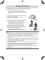
CHARGING THE BATTERY PACK
The battery pack can be charged after it has been installed onto the transceiver.
(The battery pack is provided uncharged for safety purposes.)
1 Confirm that the transceiver power is OFF.
•
While charging the transceiver with a battery pack
installed, be sure to turn the transceiver power
OFF.
2 Plug the AC adapter cable into the jack located
on the rear of the charger.
3 Plug the AC adapter into an AC outlet.
4 Slide a battery pack or a transceiver equipped
with a battery pack into the charging slot.
•
•
Make sure the metal contacts of the battery pack
mate securely with the charger terminals.
The indicator lights red and charging starts.
5 When charging is completed, the indicator
lights green. Remove the battery pack or the
transceiver from the charging slot.
•
When the charger will not be used for a long time,
unplug the AC adapter from the AC outlet.
Charging slot
Indicator
Note:
◆ Using the transceiver while charging its battery pack will interfere with correct charging.
◆ If the operating time of a battery pack decreases although the battery pack is fully and
correctly charged, the battery pack life is over. Replace the battery pack.
◆ The ambient temperature should be from 41°F (5°C) to 104°F (40°C) while charging is in
progress.
◆ The charging times provided are obtained when a battery pack discharged to 3 V/cell x 2
is charged at normal temperatures. This charging time varies depending on the degree of
discharge and the ambient charging temperature.
◆ This charger may be suitable to charge battery packs not listed herein, due to further
technology development.
◆ If the battery pack contacts are not properly mated with the charger terminals, the
indicator may blink red or may remain unlit. To resolve this problem, reinsert the battery
pack after cleaning the battery pack contacts and the charger terminals.
◆ When using this equipment near a radio or television, you may experience interference
with reception.
◆ While charging, do not connect the PC Interface cable to the transceiver.
3
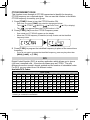
Approximate Charging Times
3 hours
Charger Status Table
Indicator color
Meaning
Red
A battery pack is in the charging slot and charging has
started.
Blinking Red
The battery pack is defective or the battery pack
contacts are not properly mated with those of the
charger.
Green
Charging is completed; remove the battery pack or the
transceiver from the charging slot.
Alternates flashing green
and orange
The temperature of the battery pack has not satisfied
the charging start temperature. Remove the battery
pack from the charger and wait until it reaches a normal
temperature before charging it again.
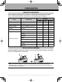
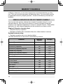
Battery Life
Before you operate the transceiver outside, using a battery pack, it is important to
know how long the battery pack will last. The operating times listed in the table
below are measured under the following cyclic conditions:
TX: 6 seconds, RX: 6 seconds, Stand-by: 48 seconds (Battery Saver: ON)
We recommend you carry extra battery packs with you, in case the battery pack
becomes depleted.
Battery Type
KNB-63L/ KNB-65L
(7.4 V)
BT-16 (9 V)
<AAA (LR03) alkaline
batteries x 6>
Output Power
Operating Time/ Hours (Approx.)
High
6 (KNB-63L)
8 (KNB-65L)
Medium
8.5 (KNB-63L)
11.5 (KNB-65L)
Low
10.5 (KNB-63L)
14 (KNB-65L)
High
6
Medium
8
Low
10
Note:
◆ The high power transmission output while using the battery case (BT-16) is 3.5 W and
lower. Additionally, as is characteristic of alkaline batteries, transmission output will
decrease as time progresses. We recommend using low power when using the battery
case.
◆ Internal resistance levels differ, depending on the battery, so when using Alkaline
batteries there are times when the actual operating time may be shorter than normal.
4
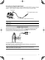
Connecting to a Cigarette Lighter Socket
To use the cigarette lighter socket, use the optional KVC-22 DC vehicular charger
adapter. When using the Charger, attach it to the vehicle as shown below.
To the jack
To the cigarette lighter socket
Charger + KVC-22
DC power cable (supplied with the KVC-22)
Note: Refer to the KVC-22 instruction manual for how to connect the charger to a cigarette
lighter socket.
CAUTION: Do not fix the Charger near an airbag nor in places where it will be a hindrance
while driving.
CONNECTING TO THE PC
Use the optional PG-4Y PC interface cable to connect the transceiver to a PC.
Plug the Speaker/ Microphone connector to the SP/MIC jack and the DB-9
connector to one of the COM (serial) ports on your PC.
To PC
PG-4Y
To download the MCP-5A software, go to:
http://www.kenwood.com/i/products/info/amateur/software_download.html
(This URL may change without notice.)
Note: No guarantee is provided for data that may be erased or destroyed due to
malfunctions of this unit or your computer.
5
GETTING ACQUAINTED
PANEL
Microphone
Speaker
PWR/VOL control
Turn clockwise to switch the transceiver ON. To switch the transceiver OFF,
turn counterclockwise until a click sounds. Rotate to adjust the volume level.
TX-RX LED
Lights red while transmitting and green while receiving a signal.
ENC Control
Rotate to select an operating frequency, Memory channel, Menu number, and
setting value or to change the scan direction, etc.
[PTT] (Push to talk) switch
Press and hold, then speak into the microphone to transmit.
[MONI]
Press and hold to unmute the speaker in order to monitor signals. Release
[MONI] to return to normal operation {page 13}.
6
Keypad
Use the keypad to perform the following operations. Additionally, you can use
the 10-key keypad for direct frequency entry and manually transmitting DTMF
tones.
Key name
Press
[KEY]
[F]
A
B
C
D
11
–
[KEY] (1s)
To turn the Lock function ON and OFF.
14
To enter VFO mode.
11
[F] - [KEY]
To copy the current Memory channel or Call
channel to the VFO (memory shift).
24
[KEY] (1s)
To start Band scan.
26
To enter Memory Channel mode.
18
[F] - [KEY]
To store the current operating frequency in the
Memory channel.
19
[KEY] (1s)
To start Memory scan
28
[KEY]
[CALL]
To turn the Function ON.
To turn the Function OFF.
[KEY]
[MR]
To enter MHz tuning mode.
Ref. page
[F] - [KEY]
[KEY]
[VFO]
Operation
To select the Call channel.
[F] - [KEY]
To store the current operating frequency to the
Call channel.
23
[KEY] (1s)
To start CALL scan.
28
15
[MENU]
1
[KEY]
To enter Menu mode.
[TONE]
2
[KEY]
To select the Signaling (Tone, CTCSS, DCS or
Cross tone) function.
[LOW]
3
[KEY]
To select an Output power.
12
[SQL]
4
[KEY]
To enter Squelch Level Adjustment mode.
10
[KEY]
To enter the Tone frequency, CTCSS
frequency or DCS code setup mode.
[T.SEL]
5
[KEY] (1s)
To start Tone frequency, CTCSS frequency or
DCS code scan.
32, 36,
37, 39
32, 36,
37, 39
[ ]
6
[KEY]
To enter the Tone Alert function setup mode.
44
[SHIFT]
7
[KEY]
To select an Offset direction.
31
[REV]
8
[KEY]
To turn the Reverse function ON or OFF.
34
[PF]
9
[KEY]
To activate the Program function.
52
7
Key name
Press
[KEY]
[LAMP]
[F] - [KEY]
Operation
Ref. page
To turn the Backlight ON.
To keep the Backlight ON continuously.
13
[STEP]
0
[KEY]
To enter the Frequency step size setup mode.
44
[ENT]
#
[KEY]
To enter Direct frequency entry mode.
12
MIC/ SP Jack
Connect the optional Speaker/ Microphone to this jack.
Also, attach an optional PG-4Y PC interface cable to this jack, to connect the
transceiver to a PC {page 5}.
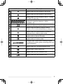
DISPLAY
Indicator
Description
Appears while using Medium output power.
Appears while using Low output power.
Appears when the Cross Tone function is ON.
Appears when the Tone function is ON.
Appears when the CTCSS function is ON.
Appears when the DCS function is ON.
Appears when Weather Alert is ON. Blinks when
receiving a signal. (TH-K20A K type only)
Appears when the Reverse function is ON.
8
Indicator
Description
Appears when the Shift function is set to plus.
Appears when the Shift function is set to minus.
Appears when the Shift function is set to –7.6 MHz.
(TH-K40E (E type) only)
Displays the operating frequency, setting
information, etc.
Displays the Memory channel number.
Appears when the Memory channel Lockout
function is ON, for the selected Memory channel.
Appears when the selected Memory channel is
registered while in Memory Input mode.
Appears while in Narrow FM mode.
Appears while in Function mode.
Performs as an S meter when receiving a signal
and displays the battery power remaining while Low
power transmitting.
Appears when the Tone Alert function is ON.
Appears when Priority scan is ON.
Appears when the VOX function is ON.
Appears when the Lock function is ON.
9
BASIC OPERATION
SWITCHING THE POWER ON/OFF
Turn the PWR/VOL control clockwise to switch the transceiver ON.
•
The power on message momentarily appears on the display.
Turn the PWR/VOL control counterclockwise to switch the transceiver OFF.
ADJUSTING THE VOLUME
Rotate the PWR/VOL control to adjust the volume. Clockwise increases the
volume and counterclockwise decreases it.
•
If you are not receiving a signal, press and hold [MONI] to unmute the speaker, then
adjust the volume control to a comfortable audio output level.
ADJUSTING THE SQUELCH
The purpose of Squelch is to mute the speaker when no signals are present.
With the squelch level correctly set, you will hear sound only while actually
receiving signals. The higher the selected squelch level, the stronger the signals
must be to receive. The appropriate squelch level depends on the ambient RF
noise conditions.
1 Press [SQL].
•
The squelch level appears on the display.
2 Rotate the ENC control to adjust the level.
•
•
•
Select the level at which the background noise is just eliminated when no signal is
present.
The higher the level, the stronger the signals must be to receive.
6 different levels can be set. 0: Minimum ~ 5: Maximum; 2 is the default value.
3 Press any key other than [MONI] or [LAMP] to store the new setting and exit
the squelch adjustment.
10
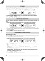
SELECTING A FREQUENCY
VFO MODE
This is the basic mode for changing the operating frequency. Rotate the ENC
control clockwise to increase the frequency and counterclockwise to decrease
the frequency.
MHz TUNING MODE
If the desired operating frequency is far away from the current frequency, it is
quicker to use the MHz Tuning Mode.
To adjust the MHz digit:
1 Press [F].
•
The MHz digit blinks.
2 Rotate the ENC control to select the desired MHz value.
3 After selecting the desired MHz value, press [F] or [ENT] to exit the MHz
Tuning Mode and return to normal VFO Mode.
4 Continue adjusting the frequency as necessary, using the ENC control.
TRANSMITTING/ RECEIVING
1 To transmit, hold the transceiver approximately 5 cm (2 inches) from your
mouth, then press and hold [PTT] and speak into the microphone in your
normal tone of voice.
•
The TX-RX LED lights red.
2 When you finish speaking, release [PTT].
•
The TX-RX LED lights green while receiving a signal.
Note: If you continuously transmit for longer than the time specified in Menu No. 19 (default
is 10 minutes), the internal time-out timer generates a warning beep and the transceiver
stops transmitting. In this case, release [PTT] and let the transceiver cool down for a while,
then press [PTT] again to resume transmitting.
11
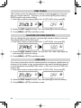
DIRECT FREQUENCY ENTRY
In addition to rotating the ENC control, there is another way to select the
frequency. When the desired frequency is far away from the current frequency,
you can directly enter a frequency using the numeric keypad.
1 Press [VFO].
•
You must be in the VFO Mode to make the direct frequency entry.
2 Press [ENT].
3 Press the numeric keys ([STEP] (0) to [PF] (9)) to enter your desired
frequency. [LAMP] ( ) allows you to complete the MHz digits entry.
•
•
Pressing [ENT] fills all remaining digits (the digits you did not enter) with 0 and
completes the entry. For example, to select 145.000 MHz, press [MENU] (1),
[SQL] (4), and [T.SEL] (5), then press [ENT] to complete the entry.
If you want to revise the MHz digits only, leaving the kHz digits as they are, press
[VFO] in place of [ENT].
Note:
◆ If the entered frequency does not match the current frequency step size, the frequency is
automatically rounded down to the next available frequency.
◆ When the desired frequency cannot be entered exactly, confirm the frequency step size.
◆ If you rotate the ENC control while entering the frequency, the transceiver clears the
entry.
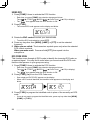
SELECTING AN OUTPUT POWER
Selecting a lower transmit power is the best way to reduce battery consumption, if
communication is still reliable.
Press [LOW] to toggle between high, medium and low power.
•
•
•
No icon appears when using high transmit power.
The “
” icon appears when using medium transmit power.
The “
” icon appears when using lower transmit power.
Note: When the transceiver overheats due to ambient high temperature or continuously
transmitting, the protective circuit may activate, lowering the transmit output power.
12
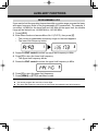
REMAINING BATTERY CAPACITY
You can confirm the remaining battery capacity when you transmit in low power.
To check the remaining capacity:
•
The bar-graph shows the remaining battery capacity.
: High battery power
:
↑
:
↑
:
Low battery power
or no display :
Recharge or replace the batteries.
Note: You may not be able to transmit at high power if the battery remaining indicator shows
low battery power.
BACKLIGHT
Press [LAMP] to illuminate the display and keys.
•
•
•
The light turns OFF approximately 5 seconds after releasing [LAMP].
Press any key (including [PTT]) other than [LAMP] while the display and keys are lit to
restart the 5-second timer.
Continuing to press [LAMP] after having pressed it will illuminate the display and keys
for as long as you hold the key.
Press [F] - [LAMP] to keep the light ON continuously.
•
The light remains ON until you press [F] - [LAMP] again.
MONITOR
When you are receiving while the squelch function is ON, weak signals may
become intermittent.
If the CTCSS, DCS or Tone Alert function is ON, you may want to disable the
squelch function temporarily to monitor the current channel activities.
1 Press and hold [MONI].
•
The speaker is unmuted and you can monitor the signals.
2 Release [MONI] to return to normal operation.
13
LOCK FUNCTION
The lock function disables most of the keys to prevent you from accidentally activating
a function.
1 Press [F] (1s) to turn the Lock function ON.
•
The “
” icon appears when the Lock function is ON.
•
The following keys cannot be locked:
[F], [PTT], [LAMP], [MONI], [SQL], PWR/VOL control and microphone PF key.
2 Press [F] (1s) to unlock the keys.
Note:
◆ You cannot perform the Transceiver Reset while the Lock function is ON.
◆ You can select the lock type from Menu No. 3.
14
MENU SETUP
WHAT IS A MENU?
Many functions on this transceiver are selected or configured via a softwarecontrolled Menu rather than through the physical controls of the transceiver.
Once you become familiar with the Menu system, you will appreciate its
versatility. You can customize the various timings, settings and programming
functions on this transceiver to meet your needs without using many controls and
switches.
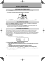
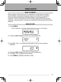
MENU ACCESS
1 Press [MENU].
•
A brief explanation of the Menu and the Menu No. appear on the display.
2 Rotate the ENC control to select your desired Menu No.
3 Press [F] < OK > to configure the parameter of the currently selected
Menu No.
4 Rotate the ENC control to select your desired parameter.
5 Press [F] < OK > to store the new setting.
6 Press [MENU] or [PTT] to exit Menu mode.
15
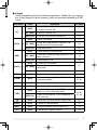
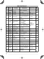
MENU FUNCTION LIST
No.
Display
1
P.ON.MSG
Power On
message
Up to 6 characters
–
2
BEEP
Key Beep
OFF/ ON
ON
3
LOCK
Lock type
KEY/ FRQ/ KEY.FRQ
KEY.FRQ
4
SAVE
Battery saver
5
APO
Automatic PowerOFF
6
P.VFO
7
OFFSET
8
ARO
9
N.FM
10
B.SHIFT
11
M.NAME Memory name
12
13
14
15
16
Description
Programmable
VFO
Repeater Offset
Frequency
Automatic
Repeater Offset
46
1.0 (sec)
47
30 (min)
48
It differs
between the
model and
type.
OFF/ ON
43
31
34
48
Beat shift
OFF/ ON
OFF
49
Up to 6 characters
–
21
NAME/ FREQ
NAME
22
OFF/ ON
OFF
29
TO/ CO/ SEEK
TO
30
OFF/ ON
OFF
28
OFF/ 1 ~ 9
OFF
49
OFF/ ON
OFF
Memory display
type
Memory channel
L.OUT
lockout
Scan resume
RESUME
method
PR.SCAN Priority scan
VOX gain
18
VOX.DLY VOX delay time
16
45
OFF
VOX.BSY VOX busy
20
0.000 ~ 29.950 (MHz)
Ref.
Page
OFF/ ON
17
19
OFF/ 0.2/ 0.4/ 0.6/ 0.8/
1.0/ 2.0/ 3.0/ 4.0/ 5.0
(sec)
OFF/ 30/ 60/ 90/ 120/
180 (min)
TH-K20A/E:
136 ~ 173 MHz
TH-K40A/E:
400 ~ 469 MHz
Default Setting
Narrow FM
M.DISP
VOX
Setting Values
TOT
Time-out Timer
BCL
Busy channel
lockout
250/ 500/ 750/ 1000/
1500/ 2000/ 3000 (ms)
0.5/ 1.0/ 1.5/ 2.0/ 2.5/
3.0/ 3.5/ 4.0/ 4.5/ 5.0/
10.0 (min)
OFF/ ON
500 (ms)
50
10.0 (min)
51
OFF
No.
Display
21
TX.INH
TX inhibit
OFF/ ON
OFF
22
M.SENS
Microphone
Sensitivity
HIGH/ MEDIUM/ LOW
MEDIUM
Panel PF key
1750/ WX/ N.FM/
PR.SCAN/ M.DISP
It differs
between the
model and
type.
23
PF KEY
Description
24
PF 1
Microphone PF 1
key
25
PF 2
Microphone PF 2
key
26
PF 3
Microphone PF 3
key
27
MIC.LK
28
29
Setting Values
Default Setting
Ref.
Page
52
VFO/ MR/ CALL/ UP/
DOWN/ TONE/ T.SEL/
SHIFT/ REV/ 1750/
WX/ N.FM/ PR.SCAN/
M.DISP/ SQL/ LOW/
STEP/ L.OUT/ MONI/
VFO
Microphone key
Lock
OFF/ ON
OFF
53
DTMF.MR
DTMF memory
(Automatic dialer)
0 ~ F ch
Up to 16 digits
0 ch
40
DT.SPD
DTMF TX speed
50/ 100/ 150 (ms)
100 (ms)
41
MR
CALL
30
DT.HOLD DTMF TX hold
OFF/ ON
OFF
31
DT.PAUS DTMF pause time
100/ 250/ 500/ 750/
1000/ 1500/ 2000 (ms)
500 (ms)
32
DT.LOCK DTMF key Lock
OFF/ ON
OFF
33
1750.HD 1750 Hz TX hold
OFF/ ON
OFF
35
Battery type
LI-ION/ ALKALI
LI-ION
53
42
34
BATT
35*
WX.ALT
Weather alert
OFF/ ON
OFF
54
99
RESET
Reset type
PART/ FULL
PART
58
* Available only for the TH-K20A K type model.
Note: Default settings are subject to change.
17
MEMORY CHANNELS
In Memory channels, you can store frequencies and related data that you often
use. Then you need not reprogram the data every time. You can quickly recall a
programmed channel by simple operation. A total of 200 Memory channels are
available.
SIMPLEX & REPEATER OR ODD-SPLIT MEMORY CHANNEL?
You can use each memory channel as a simplex & repeater channel or as an
odd-split channel. Store only one frequency to use as a simplex & repeater
channel or two separate frequencies to use as an odd-split channel. Select either
application for each channel depending on the operations you have in mind.
Simplex & Repeater channels allow:
• Simplex frequency operation
• Repeater operation with a standard offset (if an offset direction is stored)
Odd-split channels allow:
• Repeater operation with a non-standard offset
The data listed below can be stored in each Memory channel:
Simplex &
Repeater
Odd-split
Receive/ Transmit frequency
Yes
No
Receive/ Transmit frequency step size
Yes
No
Receive only frequency
No
Yes
Receive only frequency step size
No
Yes
Transmit only frequency
No
Yes
Transmit only frequency step size
No
Yes
Offset frequency
Yes
No
Tone On/Off
Yes
Yes
Tone frequency
Yes
Yes
CTCSS On/Off
Yes
Yes
CTCSS frequency
Yes
Yes
DCS On/Off
Yes
Yes
DCS code
Yes
Yes
Cross tone On/Off
Yes
Yes
Shift (Offset direction)
Yes
No
Reverse On/Off
Yes
No
Parameter
18
Simplex &
Repeater
Odd-split
Memory channel lockout *
Yes
Yes
Narrow FM
Yes
Yes
Beat shift
Yes
Yes
Parameter
* Program Scan Memory and the Priority channel cannot be stored as ON or OFF for Memory
channel lockout.
STORING SIMPLEX AND STANDARD REPEATER FREQUENCIES
1 Press [VFO] to enter VFO mode.
2 Rotate the ENC control to select your desired frequency.
•
You can also directly enter a desired frequency using the keypad.
3 If storing a standard repeater frequency, select the following data:
• Offset direction
• Tone function, if necessary
• CTCSS/ DCS function, if necessary
If storing a simplex frequency, you may select other related data (CTCSS or DCS
settings, etc.).
4 Press [F] - [MR].
•
A memory channel number appears and blinks.
•
•
When the channel has stored data, the “
” icon appears.
Memory channel numbers L0/U0 ~ L2/U2 and Pr (Priority Channel) are reserved for
other functions.
5 Rotate the ENC control to select the memory channel in which you want to
store the data.
6 Press [MR] to store the data to the channel.
Note: If you store the data in a Memory channel that already has data stored in it, the old
data will be cleared and the new data will be stored.
19
STORING ODD-SPLIT REPEATER FREQUENCIES
Some repeaters use a receive/transmit frequency pair with a non-standard offset.
If you store two separate frequencies in a memory channel, you can operate on
those repeaters without programming the offset frequency and direction.
1 Store the desired receiving frequency and related data by following the
procedure given for simplex or standard repeater frequencies.
2 Press [VFO], then rotate the ENC control to select the desired transmit
frequency.
•
You can also directly enter a desired frequency using the keypad.
3 Press [F] - [MR], then rotate the ENC control to select the memory channel
you programmed in step 1.
4 Press [PTT] + [MR].
•
The transmit frequency is stored in the memory channel.
Note: When you recall an odd-split memory channel, “ ” and “
” appear on the display.
To confirm the transmit frequency, press [REV] (Reverse function).
RECALLING A MEMORY CHANNEL
USING THE ENC CONTROL
1 Press [MR] to enter Memory Recall Mode. The memory channel last used is
recalled.
2 Rotate the ENC control to select your desired memory channel.
•
•
You cannot recall an empty memory channel.
To restore VFO Mode, press [VFO].
USING A NUMERIC KEYPAD
You can also recall a memory channel by entering a desired memory channel
number with the keypad.
1 Press [MR] to enter Memory Recall Mode.
2 Press [ENT], then enter the channel number.
•
•
20
For example, to recall channel 149, press [ENT], [MENU] (1), [SQL] (4), [PF] (9).
You can also enter a memory channel number that is less than 10 by pressing
[ENT] after entering the channel number. For example, to recall memory channel
9, press [ENT], [PF] (9), [ENT]. You can also press [ENT], [STEP] (0), [PF] (9).
Note:
◆ You cannot recall an empty memory channel. An error beep sounds.
◆ You cannot recall the Program Scan memory channels (L0/U0 ~ L2/U2) or Priority
Channel (Pr) using the numeric keypad.
◆ When recalling an odd-split memory channel, “ ” and “
” appear on the display.
Press [REV] (Reverse function) to display the transmit frequency.
◆ After recalling a memory channel, you may modify data such as Tone or CTCSS.
However, these settings are cleared once you select another channel or the VFO Mode.
To permanently store the data, overwrite the channel contents.
NAMING A MEMORY CHANNEL
You can name memory channels using up to 6 alphanumeric characters. When
you recall a named memory channel, its name appears on the display in place of
the stored frequency. Names can be call signs, repeater names, cities, names of
people, etc.
1 Press [MR], then rotate the ENC control to select your desired memory
channel.
2 Enter Menu mode and access Menu No. 11 (M.NAME), then press [F].
•
A blinking cursor appears.
3 Rotate the ENC control to select a desired alphanumeric character.
•
You can enter the following alphanumeric characters:
0 ~ 9, A ~ Z, - (hyphen), / (slash), and a space.
4 Press [MR].
•
•
•
The cursor will move to the next digit.
You can move the cursor to the left or right by pressing [VFO] or [MR].
Press [CALL] to delete the character at the current cursor position.
5 Repeat steps 3 and 4 to enter up to 6 digits.
6 Press [F] to store the name.
7 Press [MENU] or [PTT] to exit Menu mode.
Note:
◆ You cannot name the Call Channel.
◆ You cannot assign a Memory name to a channel that does not contain data.
◆ You can overwrite stored names by repeating steps 2 to 6.
◆ The stored name is erased when you clear the Memory channel data.
21
MEMORY DISPLAY TYPE
After storing a Memory name, the Memory name appears in place of the
operating frequency. However, you can still display the operating frequency, if
desired. To display the frequency rather than Memory name, access Menu No.
12 (M.DISP) and select “FREQ”. This menu toggles the display mode between
the Memory name (“NAME”) and frequency display (“FREQ”).
1 Enter Menu mode and access Menu No. 12 (M.DISP), then press [F].
2 Rotate the ENC control to set the display type to “NAME” or “FREQ”, then
press [F] to store the setting.
3 Press [MENU] or [PTT] to exit Menu mode.
Note: Even when set to “NAME”, the frequency will appear on the display while pressing
[MONI].
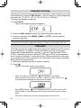
CLEARING A MEMORY CHANNEL
To clear the data from an individual memory channel:
1 Recall the memory channel you want to clear.
2 Turn the transceiver OFF
3 Press [MR] + Power ON.
•
A confirmation message appears.
4 Press [MR] to clear the channel data.
•
•
The contents of the memory channel are cleared.
To cancel, press any key other than [MR], [MONI] or [LAMP].
Note:
◆ The Call Channel data cannot be cleared.
◆ You can also clear the Priority Channel and the L0/U0 ~ L2/U2 channels.
◆ While the transceiver is in Channel Display Mode or Lock function is activated, you
cannot clear the channel data.
22
CALL CHANNEL
The Call Channel can be recalled instantly, no matter the frequency on which you
are operating the transceiver. For instance, you may use the Call Channel as an
emergency channel within your group. In this case, Call Scan will be useful.
The default Call Channel frequency is 144.000 MHz (TH-K20A/E)/ 430.000 MHz
(TH-K40A/E).
Note: Unlike memory channels 0 to 199, the Call Channel cannot be cleared.
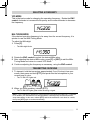
RECALLING THE CALL CHANNEL
Press [CALL] to recall the Call Channel.
•
The Call Channel frequency and “C” appear.
•
To return to the previous frequency, press [CALL] again.
REPROGRAMMING THE CALL CHANNEL
1 Select your desired frequency and related data (Tone, CTCSS, DCS, or offset
direction, etc.).
•
When you program the Call Channel as an odd-split channel, select a receiving
frequency first.
2 Press [F] - [CALL].
•
The selected frequency and related data are stored in the Call Channel.
To also store a separate transmit frequency, continue with the following steps.
3 Select the desired transmit frequency.
4 Press [F], then press [PTT] + [CALL].
•
The separate transmit frequency is stored in the Call Channel.
Note:
” appear on the display.
◆ When you recall an odd-split Call Channel, “ ” and “
◆ Transmit offset status and Reverse status are not stored in an odd-split Call Channel.
23
MEMORY CHANNEL TRANSFER
MEMORY TO VFO TRANSFER
After retrieving frequencies and associated data from Memory Recall mode, you
can copy the data to the VFO. This function is useful, for example, when the
frequency you want to monitor is near the frequency stored in a memory channel.
1 Press [MR], then turn the ENC control to recall a desired memory channel.
2 Press [F] - [VFO] to copy the memory channel data to the VFO.
Note:
◆ When transferring an odd-split channel, the Reverse status, Offset direction, and
Transmit frequency are not transferred.
◆ You can also transfer the Program Scan memory channels (L0/U0 ~ L2/U2) and Priority
channel (Pr) to the VFO.
◆ When selecting the Call channel, rotating the ENC control will transfer the data to the
VFO.
CHANNEL TO CHANNEL TRANSFER
You can also copy channel information from one memory channel to another.
This function is useful when storing frequencies and associated data that you
temporarily change in Memory Recall mode.
1 Press [MR], then turn the ENC control to recall a desired memory channel.
2 Press [F] - [MR].
3 Select the memory channel where you would like the data copied, using the
ENC control.
4 Press [MR] to copy the memory channel data to the new channel.
Note: When transferring to the Program Scan memory channels (L0/U0 ~ L9/U9) and the
Priority channel (Pr), the Memory Channel Lockout information is not copied.
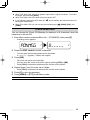
CHANNEL DISPLAY MODE
While in this mode, the transceiver displays only memory channel numbers (or
Memory names if they have been stored) instead of frequencies.
Press [PTT] + [MR] + Power ON.
•
The transceiver displays the memory channel number in place of the operating
frequency.
To recover normal operation, turn the transceiver OFF and press [PTT] + [MR] +
Power ON again.
24
Note:
◆ To enter the Channel Display Mode, you must have at least one memory channel that
contains the data.
◆ If the memory channel contains the Memory name data, the Memory name is displayed in
place of the “CH” characters.
◆ You cannot enter Channel Display mode while Key Lock is ON.
While in the Channel Display mode, only the following keys can be operated.
[KEY]
PTT
MONI
SQL
F
MR
LAMP
ENT
CALL
LOW
[F] - [KEY]
MONI
LAMP
[KEY] (1s)
F
MR
CALL
While transmitting:
MONI
A [F]
B [VFO]
C [MR]
D [CALL]
0
1
2
3
4
5
6
7
8
9
#
25
SCAN
Scan is a useful feature for hands-off monitoring of your favorite frequencies.
Becoming comfortable with all types of Scan will increase your operating
efficiency.
This transceiver provides the following type of scans:
Band Scan
Scans all frequencies on the current band.
Program Scan
Scans the specified frequency ranges stored in Memory
channels L0/U0 ~ L2/U2.
Memory Scan
Scans all frequencies stored in the Memory channels.
CALL Scan
Priority Scan
Scans the Call channel as well as the currently selected VFO
frequency or Memory channel.
Checks the activities on the Priority channel (Pr) every
3 seconds.
Note:
◆ When the CTCSS or DCS function is activated, the transceiver stops at a busy frequency
and decodes the CTCSS tone or DCS code. If the tone or code matches, the transceiver
unmutes. Otherwise, it resumes scanning.
◆ Press and hold [MONI] to pause scan in order to monitor the scanning frequency.
Release [MONI] to resume scanning.
◆ Pressing [MENU] causes scan to stop.
◆ If you press any key other than the following keys during scan, the transceiver exits scan
(excluding Priority Scan): [MONI], [LAMP], [F], [SQL], [F] (1s), or [F] - [LAMP].
BAND SCAN
The transceiver scans the entire band of the frequency you selected. For
example, if you are operating and receiving at 144.525 MHz, it scans all the
frequencies available for the 2 m band. When the current VFO receiving
frequency is outside the Program Scan frequency range {page 38}, the
transceiver scans the entire frequency range available for the current VFO.
1 Press [VFO].
2 Rotate the ENC control to select the frequency outside of the Program Scan
frequency range.
3 Press [VFO] (1s).
•
•
•
Scan starts at the current frequency.
The 1 MHz point blinks while scanning is in progress.
To change the scan direction, rotate the ENC control clockwise <upward scan> or
counterclockwise <downward scan>.
4 To exit Band Scan, press any key other than [MONI], [LAMP], [F], [SQL],
[F] (1s), or [F] - [LAMP].
26
PROGRAM SCAN
You can limit the scanning frequency range. There are 3 memory channel pairs
(L0/U0 ~ L2/U2) available for specifying the start and end frequencies. Program
Scan monitors the range between the start and end frequencies that you have stored
in these memory channels. Before performing Program Scan, store the Program
Scan frequency range to one of the memory channel pairs (L0/U0 ~ L2/U2).
STORING A PROGRAM SCAN FREQUENCY RANGE
1 Press [VFO], then rotate the ENC control to select your desired start
frequency.
2 Press [F] - [MR], then rotate the ENC control to select a memory channel
from L0 ~ L2.
3 Press [MR] to store the start frequency in the memory channel.
4 Rotate the ENC control to select your desired end frequency.
5 Press [F] - [MR], then rotate the ENC control to select a channel from U0 ~
U2, corresponding to the channel selected in step 2.
• For example, if you selected L0 in step 3, select U0 for the end frequency.
6 Press [MR] to store the end frequency in the memory channel.
USING PROGRAM SCAN
1 Press [VFO], then rotate the ENC control to select a frequency within the
frequency range of memory channel L0/U0 ~ L2/U2.
2 Press [VFO] (1s) to start Program Scan.
•
The 1 MHz point blinks while scanning is in progress.
3 To stop Program Scan, press any key other than [MONI], [LAMP], [F], [SQL],
[F] (1s), or [F] - [LAMP].
Note:
◆ If you press [MONI], Program Scan temporarily pauses. Release [MONI] to resume
scanning.
◆ The transceiver stops scanning when it detects a signal.
◆ If more than 2 Program Scan channel pairs are stored and the frequency range among
the pairs overlaps, the smaller Program Scan memory channel number has priority.
◆ To perform Program Scan, the “L” channel frequency must be lower than the “U” channel.
27
MEMORY SCAN
1 Press [MR] (1s).
•
•
Scan starts from the last memory channel number and ascends up through the
channel numbers (default).
Rotate the ENC control to change the scanning direction.
2 To stop Memory Scan, press any key other than [MONI], [LAMP], [F], [SQL],
[F] (1s), or [F] - [LAMP].
Note:
◆ You must have 2 or more memory channels that contain data, excluding special function
memory channels (L0/U0 ~ L2/U2, and Pr).
◆ You can perform Memory Scan in Channel Display Mode {page 24}.
CALL SCAN
1 Select the frequency (in VFO or Memory Recall Mode) you want to monitor.
•
•
In VFO Mode, rotate the ENC control to select the desired frequency.
In Memory Recall Mode, rotate the ENC control to select the memory channel you
want to monitor.
2 Press [CALL] (1s) to start the Call Scan.
3 The Call Channel and the selected VFO frequency or memory channel are
monitored.
4 To stop Call Scan, press any key other than [MONI], [LAMP], [F], [SQL],
[F] (1s), or [F] - [LAMP].
Note:
◆ The transceiver stops scanning when it detects a signal.
◆ You can perform Call Scan even if the recalled memory channel has been locked out.
PRIORITY SCAN
You may sometimes want to check your favorite frequency activities while
monitoring other frequencies. In this case, use the Priority Scan function.
Priority Scan checks the activities of the Priority Channel every 3 seconds. If the
transceiver detects a signal on the Priority Channel, it recalls the frequency.
Note: If you do not operate any control or key for 3 seconds after the signal drops, the
transceiver returns to the original frequency and resumes Priority Scan.
PROGRAMMING A PRIORITY CHANNEL
1 Press [VFO], then rotate the ENC control to select your desired Priority
Channel frequency.
2 Select CTCSS or DSC, if necessary.
3 Press [F] - [MR].
•
The memory channel number appears and blinks.
4 Rotate the ENC control to select “Pr”.
28
5 Press [MR] to store the data on the Priority Channel.
USING PRIORITY SCAN
1 Enter Menu mode and access Menu No. 15 (PR.SCAN), then press [F].
2 Rotate the ENC control to select “ON”, then press [F] to store the setting.
3 Press [MENU] or [PTT] to exit Menu mode.
•
The “
” icon appears when the Priority Scan is ON.
Note:
◆ If a signal is received on a Priority Channel with a CTCSS or DCS code programmed, the
Priority Channel is recalled only when the programmed tone/ code matches.
◆ Press and hold [MONI] to pause Priority Scan when the transceiver is not displaying the
Priority Channel. Release [MONI] to resume Priority Scan.
◆ If you clear the Priority Channel, Priority Scan stops.
◆ You can also press any key other than [MONI], [F], [SQL] (Squelch level adjustment),
” is blinking.
[F] (1s) (Key lock) and [PTT] to exit Priority Scan while “
MEMORY CHANNEL LOCKOUT
You can lock out memory channels that you prefer not to monitor during Memory
Scan.
1 Press [MR] to enter Memory Recall Mode.
2 Rotate the ENC control to select the memory channel to be locked out.
3 Enter Menu mode and access Menu No. 13 (L.OUT), then press [F].
4 Rotate the ENC control to select “ON”, then press [F] to store the setting.
5 Press [MENU] or [PTT] to exit Menu mode.
•
The “
” icon appears below the memory channel number, indicating the channel
is locked out.
Note:
◆ The Program Scan channels (L0/U0 ~ L2/U2) and Priority Channel (Pr) cannot be locked
out.
◆ Even if a memory channel is locked out, you can perform Call Scan between the Call
Channel and the memory channel.
29
SELECTING A SCAN RESUME METHOD
The transceiver stops scanning at a frequency or Memory channel on which a
signal is detected. It then continues scanning according to which resume mode
you have selected. You can choose one of the following modes. The default is
Time-operated mode.
TO
Time Operated
mode
CO
Carrier Operated
mode
SEEK Seek mode
The transceiver remains on a busy frequency or
Memory channel for approximately 5 seconds, and
then continues to scan even if the signal is still
present.
The transceiver remains on a busy frequency or
Memory channel until the signal drops out. There is
a 2 second delay between signal drop-out and scan
resumption.
The transceiver remains on a busy frequency or
Memory channel even after the signal drops out and
does not automatically resume scanning.
1 Enter Menu mode and access Menu No. 14 (RESUME), then press [F].
2 Rotate the ENC control to select a Scan Resume mode from “TO”, “CO” or
“SEEK”, then press [F] to store the setting.
3 Press [MENU] or [PTT] to exit Menu mode.
30
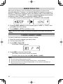
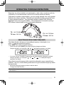
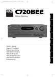
OPERATING THROUGH REPEATERS
Repeaters are often installed and maintained by radio clubs, sometimes with the
cooperation of local businesses involved in the communications industry.
Compared to simplex communication, you can usually transmit over much greater
distances by using a repeater. Repeaters are typically located on mountain tops
or other elevated locations. They generally operate at higher ERP (Effective
Radiated Power) than a typical station. This combination of elevation and high
ERP allows communications over considerable distances.
TX: 144.725 MHz
TX tone: 88.5 Hz
TX: 144.725 MHz
TX tone: 88.5 Hz
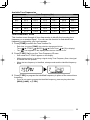
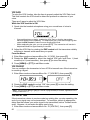
SELECTING AN OFFSET DIRECTION (SHIFT)
The offset direction allows your transmitting frequency to be higher (+) or
lower (–) than the receiving frequency.
Press [SHIFT] to select an offset direction.
•
Each time you press [SHIFT], the offset direction changes as follows:
Simplex operation (no offset) ➡ “
•
”➡“
” ➡ Simplex operation (no offset)
If you are using a TH-K40E (E type) model, the offset direction changes as follows:
Simplex operation (no offset) ➡ “
operation (no offset)
”➡“
”➡ “
” (–7.6 MHz) ➡ Simplex
If the offset transmit frequency falls outside the allowable range, transmitting is
inhibited. Use one of the following methods to bring the transmit frequency within
the band limits:
•
•
Move the receiving frequency further inside the band.
Change the offset direction.
Note: While using an odd-split memory channel or transmitting, you cannot change the
offset direction.
31
SELECTING AN OFFSET FREQUENCY
To access a repeater which requires an odd-split frequency pair, change the
offset frequency from the default which is used by most repeaters.
1 Enter Menu mode and access Menu No. 7 (OFFSET).
2 Rotate the ENC control to select the appropriate offset frequency value.
•
The selectable range is from 0.000 MHz to 29.950 MHz, in steps of 50 kHz.
3 Press [MENU] or [PTT] to exit Menu mode.
Note: After changing the offset frequency, the new offset frequency will also be used by
Automatic Repeater Offset.
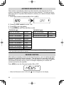
TONE FUNCTION
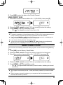
ACTIVATING THE TONE FUNCTION
To turn the Tone function on:
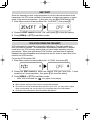
1 Press [TONE] to turn the Tone function On.
•
Each time you press [TONE], the selection changes as follows:
•
Tone (
The “
) ➡ CTCSS (
) ➡ DCS (
) ➡ Cross Tone ( ) ➡ Off (no display).
” icon appears on the display when the tone function is On.
2 Press [T.SEL].
•
The current Tone frequency appears on the display and blinks.
3 Rotate the ENC control to select your desired frequency.
•
To exit the tone frequency selection, press [PTT].
4 Press any key other than [MONI], [LAMP], or [PTT] to set the selected
frequency.
Note: If you have set up a Memory channel with a tone setting, simply recall the Memory
channel instead of setting up the tone frequency every time.
32
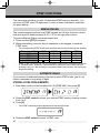
Available Tone Frequencies
Tone Frequency (Hz)
67.0
82.5
100.0
123.0
151.4
186.2
225.7
69.3
85.4
103.5
127.3
156.7
192.8
229.1
71.9
88.5
107.2
131.8
162.2
203.5
233.6
74.4
91.5
110.9
136.5
167.9
206.5
241.8
77.0
94.8
114.8
141.3
173.8
210.7
250.3
79.7
97.4
118.8
146.2
179.9
218.1
254.1
TONE FREQUENCY SCAN
This function scans through all tone frequencies to identify the incoming tone
frequency on a received signal. You can use this function to find which tone
frequency is required by your local repeater.
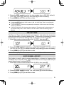
1 Press [TONE] to switch the Tone function On.
•
Each time you press [TONE], the selection changes as follows:
•
Tone (
The “
) ➡ CTCSS (
) ➡ DCS (
) ➡ Cross Tone ( ) ➡ Off (no display).
” icon appears on the display when the tone function is On.
2 Press [T.SEL] (1s) to run the Tone Frequency ID scan.
•
•
•
Scan starts and “T.SCAN” appears on the display.
While the transceiver is receiving a signal during Tone Frequency Scan, the signal
is emitted from the speaker.
When the tone frequency is identified, a beep sounds and the identified frequency
blinks.
3 Press [T.SEL] to program the identified frequency in place of the current tone
frequency.
•
If you do not want to program the identified frequency, press any key other than
[MONI], [LAMP], or [T.SEL].
33
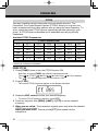
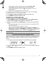
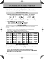
AUTOMATIC REPEATER OFFSET
This function automatically selects an offset direction and activates the Tone
function, according to the frequency that you have selected. To obtain an up-todate band plan for repeater offset direction, contact your national Amateur Radio
association.
1 Enter Menu mode and access Menu No. 8 (ARO).
2 Rotate the ENC control to select “ON”.
3 Press [F] to store the setting.
4 Press [MENU] or [PTT] to exit Menu mode.
TH-K20A K type:
TH-K20E (E type):
Under 145.100 MHz
No offset
Under 145.600 MHz
No offset
145.100 ~ 145.495 MHz
– offset
145.600 ~ 145.795 MHz
– offset
145.500 ~ 145.995 MHz
No offset
145.800 MHz and higher
No offset
146.000 ~ 146.395 MHz
+ offset
146.400 ~ 146.595 MHz
No offset
146.600 ~ 146.995 MHz
– offset
147.000 ~ 147.395 MHz
+ offset
147.400 ~ 147.595 MHz
No offset
147.600 ~ 147.995 MHz
– offset
148.000 MHz and higher
No offset
Note: Even when setting the TH-K20A/ TH-K40A M type and TH-K40E (E type) model to
“ON”, the ARO function will not operate.
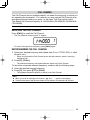
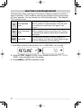
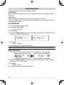
REVERSE FUNCTION
After setting a separate receive and transmit frequency, you can exchange these
frequencies using the Reverse function. This allows you to manually check the
strength of signals you receive directly from other stations, while using a repeater.
If the station’s signal is strong, move to a simplex frequency to continue the
contact and free up the repeater.
Press [REV] to turn the Reverse function ON or OFF.
•
34
When the Reverse function is ON, the “
” icon will appear on the display.
Note:
◆ If the transmit frequency is outside the allowable transmit frequency range when using
Reverse, pressing [PTT] will cause an error tone to sound and transmitting will be inhibited.
◆ If the receiving frequency is outside the receiving frequency range when using Reverse,
an error tone will sound and Reverse will not operate.
◆ The ARO (Automatic Repeater Offset) will not function when Reverse is ON.
◆ You cannot switch Reverse ON or OFF while transmitting.
TRANSMITTING A 1750 Hz TONE
Most repeaters in Europe require that a transceiver transmit a 1750 Hz tone. On
the E type model, simply pressing [PF] causes it to transmit a 1750 Hz tone. It is
also possible to program [1750] on the front panel as a [PF] key for transmitting a
1750 Hz tone.
Note: The transceiver continuously transmits a 1750 Hz tone until you release the [PF] key
(1750).
Some repeaters in Europe must receive continuous signals for a certain period of
time, following a 1750 Hz tone. This transceiver is also capable of remaining in
the transmit mode for 2 seconds after transmitting a 1750 Hz tone.
1 Enter Menu mode and access Menu No. 33 (1750.HD), then press [F].
2 Rotate the ENC control to select “ON”, then press [F] to store the setting.
3 Press [MENU] or [PTT] to exit Menu mode.
Note: While remaining in the transmit mode, the transceiver does not continuously transmit a
1750 Hz tone.
35
SIGNALING
CTCSS
You may sometimes want to hear calls only from specific persons. The
Continuous Tone Coded Squelch System (CTCSS) allows you to ignore (not
hear) unwanted calls from other persons who are using the same frequency. To
do so, select the same CTCSS tone as selected by the other persons in your
group. A CTCSS tone is subaudible and is selectable from among 42 tone
frequencies.
Available CTCSS Frequencies
CTCSS Frequency (Hz)
67.0
82.5
100.0
123.0
151.4
186.2
225.7
69.3
85.4
103.5
127.3
156.7
192.8
229.1
71.9
88.5
107.2
131.8
162.2
203.5
233.6
74.4
91.5
110.9
136.5
167.9
206.5
241.8
77.0
94.8
114.8
141.3
173.8
210.7
250.3
79.7
97.4
118.8
146.2
179.9
218.1
254.1
Note: CTCSS does not cause your conversation to be private. It only relieves you from
listening to unwanted conversations.
USING CTCSS
1 Press [TONE] 2 times to turn the CTCSS function ON.
•
Each time you press [TONE], the selection changes as follows:
•
Tone (
The “
) ➡ CTCSS (
) ➡ DCS (
) ➡ Cross Tone ( ) ➡ Off (no display).
” icon appears when the CTCSS function is ON.
2 Press [T.SEL].
•
The current CTCSS frequency appears on the display and blinks.
3 Rotate the ENC control to select your desired frequency.
•
To exit the CTCSS frequency selection, press [PTT].
4 Press any key other than [MONI], [LAMP], or [PTT] to set the selected
frequency.
5 When you are called: The transceiver squelch opens only when the selected
CTCSS tone is received.
When you make a call: Press and hold [PTT], then speak into the
microphone.
36
CTCSS FREQUENCY SCAN
This function scans through all CTCSS frequencies to identify the incoming
CTCSS frequency on a received signal. You can use this function to find which
CTCSS frequency is used by your group.
1 Press [TONE] 2 times to turn the CTCSS function ON.
•
Each time you press [TONE], the selection changes as follows:
•
Tone (
The “
) ➡ CTCSS (
) ➡ DCS (
) ➡ Cross Tone ( ) ➡ Off (no display).
” icon appears when the CTCSS function is ON.
2 Press [T.SEL] (1s) to run the CTCSS Frequency scan.
•
•
Scan starts and “CT.SCAN” appears on the display.
When the CTCSS frequency is identified, a beep sounds and the identified
frequency blinks.
3 Press [T.SEL] to program the identified frequency in place of the current tone
frequency.
•
If you do not want to program the identified frequency, press any key other than
[MONI], [LAMP], or [T.SEL].
DCS
Digital Coded Squelch (DCS) is another application which allows you to ignore
(not hear) unwanted calls. It functions the same way as CTCSS. The only
differences are the encode/ decode method and the number of selectable codes.
For DCS, you can select from 104 different codes.
Available DCS Codes
DCS Code
023
074
165
261
356
462
627
025
114
172
263
364
464
631
026
115
174
265
365
465
632
031
116
205
266
371
466
654
032
122
212
271
411
503
662
036
125
223
274
412
506
664
043
131
225
306
413
516
703
047
132
226
311
423
523
712
051
134
243
315
431
526
723
053
143
244
325
432
532
731
054
145
245
331
445
546
732
065
152
246
332
446
565
734
071
155
251
343
452
606
743
072
156
252
346
454
612
754
073
162
255
351
455
624
Note: DCS does not cause your conversation to be private. It only relieves you from
listening to unwanted conversations.
37
USING DCS
1 Press [TONE] 3 times to activate the DCS function.
•
Each time you press [TONE], the selection changes as follows:
•
Tone (
The “
) ➡ CTCSS (
) ➡ DCS (
) ➡ Cross Tone ( ) ➡ Off (no display).
” icon appears when the DCS function is ON.
2 Press [T.SEL].
•
The current DCS code appears on the display and blinks.
3 Rotate the ENC control to select your desired code.
•
To exit the DCS code selection, press [PTT].
4 Press any key other than [MONI], [LAMP], or [PTT] to set the selected
frequency.
5 When you are called: The transceiver squelch opens only when the selected
DCS code is received.
When you make a call: Press and hold [PTT], then speak into the
microphone.
DCS CODE SCAN
This function scans through all DCS codes to identify the incoming DCS code on
a received signal. You may find it useful when you cannot recall the DCS code
that the other persons in your group are using.
1 Press [TONE] 3 times to activate the DCS function.
•
Each time you press [TONE], the selection changes as follows:
•
Tone (
The “
) ➡ CTCSS (
) ➡ DCS (
) ➡ Cross Tone ( ) ➡ Off (no display).
” icon appears when the DCS function is ON.
2 Press [T.SEL] (1s) to run the DCS Code scan.
•
•
Scan starts and “DCS.SCN” appears on the display.
When a DCS code is identified, the identified code appears on the display and
blinks.
3 Press [T.SEL] to program the identified code in place of the currently set DCS
code.
•
38
If you do not want to program the identified code, press any key other than [MONI],
[LAMP], or [T.SEL].
CROSS TONE
You can set separate signaling types by TX and RX for when you access a
repeater that uses different encode/ decode signaling.
1 Press [TONE] 4 times to activate the Cross Tone function.
•
Each time you press [TONE], the selection changes as follows:
•
) ➡ DCS (
) ➡ Cross Tone ( ) ➡ Off (no display).
Tone ( ) ➡ CTCSS (
The “
” icon appears when the Cross Tone function is ON.
2 Press [T.SEL].
•
The Cross Tone setting appears on the display.
3 Rotate the ENC control to select your desired Cross Tone setting.
•
Setting
TX
RX
DCS/–
DCS
off
T/DCS
Tone
DCS
DCS/CT
DCS
CTCSS
T/CT
Tone
CTCSS
Icon <TX>
Icon <RX>
To exit the Cross Tone selection, press [PTT].
4 Press any key other than [MONI], [LAMP], or [PTT] to set the selected setting.
39
DTMF FUNCTIONS
This transceiver provides you with 16 dedicated DTMF memory channels. You
can store a DTMF code (16 digits max.) in each of these channels to recall later
for speed dialing.
MANUAL DIALING
The numeric keypad functions as a DTMF keypad; the 12 keys found on a touchtone phone plus 4 additional keys (A, B, C, D) on the right most column.
To perform Manual Dialing, follow the steps below.
1 Press and hold [PTT] to transmit.
2 While transmitting, press the keys in sequence on the keypad, to send the
DTMF tones.
•
The corresponding DTMF tones are transmitted and monitored through the speaker.
Frequency (Hz)
697
770
852
941
•
1209
1
4
7
1366
2
5
8
0
1477
3
6
9
#
1633
A
B
C
D
When DTMF TX Hold is ON, you do not need to continuously press [PTT] to remain
in Transmit Mode. However, Transmit Mode is retained for only 2 seconds after
pressing a key, so if the next key is not pressed within this time limit, the transceiver
stops transmitting.
AUTOMATIC DIALER
If you use the 16 dedicated memory channels to store DTMF codes, you do not
need to remember a long string of digits.
STORING A DTMF CODE IN MEMORY
1 Enter Menu mode and access Menu No. 28 (DTMF.MR), then press [F].
2 Rotate the ENC control to select your desired DTMF memory channel number
from 0 to F.
3 Press [F].
•
The DTMF code entry display appears and the last digit blinks.
4 Rotate the ENC control to select a DTMF code.
40
•
•
•
•
5
6
7
8
You can move the cursor to the left or right by pressing [VFO] or [MR].
Press [CALL] to delete the character at the current cursor position.
On the transceiver display, DTMF code “ ” is represented by “E” and “#” is
represented by “F”.
When a space is entered, it becomes a “Pause” code.
Press [F] to select the DTMF code and move the cursor to the next digit.
Repeat steps 4 and 5 to enter up to 16 digits.
To complete the entry, press [F] without selecting a DTMF code.
Press [MENU] or [PTT] to exit Menu mode.
TRANSMITTING A STORED DTMF CODE
1 While pressing and holding [PTT], press [MONI].
2 Release [MONI] (continue pressing [PTT]), then rotate the ENC control to
select the desired DTMF memory channel number (d0 ~ dF).
3 While still holding [PTT], press [MONI] again to transmit the selected DTMF
tones.
•
•
•
The code stored in the channel scrolls across the display, accompanied by DTMF
tones from the speaker.
After transmitting, the frequency display is restored.
If you do not need to confirm the memory channel contents, press [STEP] (0) ~
[PF] (9), [F] (A) ~ [CALL] (D), [LAMP] ( ) (E), and [ENT] (#) (F) instead of turning
the ENC control in step 2, to select a channel number. The stored DTMF code will
be immediately transmitted. (You do not need to press [MONI] in step 3.)
Note: If you select an empty DTMF memory channel and press [MONI], the frequency
display is restored.
ADJUSTING THE DTMF CODE TRANSMIT SPEED
Some repeaters may not respond correctly if a DTMF code is transmitted at fast
speed. If this happens, change the DTMF code transmit speed; the default is
100 ms.
1 Enter Menu mode and access Menu No. 29 (DT.SPD), then press [F].
2 Rotate the ENC control to select 50/ 100/ 150 ms, then press [F] to store the
setting.
3 Press [MENU] or [PTT] to exit Menu mode.
41
DTMF TX HOLD
This function causes the transceiver to remain in transmit mode for 2 seconds
after you release each key. Therefore, you can release [PTT] while sending
DTMF tones through manual dialing.
1 Enter Menu mode and access Menu No. 30 (DT.HOLD), then press [F].
2 Rotate the ENC control to select “ON”, then press [F] to store the setting.
3 Press [MENU] or [PTT] to exit Menu mode.
ADJUSTING THE PAUSE DURATION
You can change the pause duration (a space digit) stored in memory channels.
The default setting is 500 milliseconds.
1 Enter Menu mode and access Menu No. 31 (DT.PAUS), then press [F].
2 Rotate the ENC control to select 100/ 250/ 500/ 750/ 1000/ 1500/ 2000 ms,
then press [F] to store the setting.
3 Press [MENU] or [PTT] to exit Menu mode.
DTMF LOCK
If you have a transceiver with the optional speaker microphone installed and are
carrying it in the holder or bag, you sometimes may want to disable the keypad
to avoid accidental transmitting DTMF codes. In this case, turn the DTMF Lock
function ON.
1 Enter Menu mode and access Menu No. 32 (DT.LOCK), then press [F].
2 Rotate the ENC control to select “ON”, then press [F] to store the setting.
3 Press [MENU] or [PTT] to exit Menu mode.
42
AUXILIARY FUNCTIONS
PROGRAMMABLE VFO
If you want to limit the operating frequencies within a certain range, program the lower
and upper frequency limits to the programmable VFO parameters. For example, if
you select 144 MHz for the lower limit and 145 MHz for the upper limit, the tunable
range will be limited from 144.000 MHz to 145.995 MHz.
1 Press [VFO].
2 Enter Menu mode and access Menu No. 6 (P.VFO), then press [F].
• The current programmable frequency range for the band appears.
• The lower limit frequency blinks.
3 Rotate the ENC control to select the lower limit frequency in MHz.
4 Press [F] to store the lower limit frequency.
• The upper limit frequency blinks.
5 Rotate the ENC control to select the upper limit frequency in MHz.
6 Press [F] to store the upper limit frequency.
7 Press [MENU] or [PTT] to exit Menu mode.
Note:
◆ You cannot program the 100 kHz or lower digits.
◆ The upper limit frequency cannot be set lower than the selected lower limit frequency.
43
FREQUENCY STEP SIZE
Choosing the correct frequency step size is essential in order to select your exact
receive frequency using the ENC control. You can select your desired frequency
step size from: 5, 6.25, 10, 12.5, 15, 20, 25, 30, 50, or 100 (kHz).
To change the frequency step size:
1 Press [STEP].
• The current frequency step size appears.
2 Rotate the ENC control to select your desired frequency step size.
3 Press any key other than [MONI], [LAMP], or [PTT] to set the selected
frequency step size.
Note: If you change to a frequency step size that does not match the current operating frequency,
the transceiver automatically adjusts the frequency to match the new frequency step size.
TONE ALERT
Tone Alert provides an audible alarm when signals are received on the frequency
you are monitoring. In addition, it shows the number of hours and minutes
elapsed after signals have been received. If you use Tone Alert with CTCSS
or DCS, it sounds only when a received CTCSS tone or DCS code matches the
tone or code you selected. Turning this function ON is convenient for when you
are not sitting in front of the transceiver, as confirmation of the receipt is possible
while away from the transceiver.
1 Select your desired frequency or memory channel.
2 Press [ ].
•
The OFF/ ON setting appears on the display.
•
•
When Tone Alert is set to ON, the “
” icon appears on the display.
When the signal is received for more than 1 second, an alarm sounds, the “
icon blinks and the elapsed time appears on the display.
•
•
Press [PTT] while the “
” icon is blinking to turn the Tone Alert function OFF.
When 9 hours and 59 minutes pass after a signal has been received, counting
stops.
Each time a new signal is received, the elapsed time resets to 0:00.
•
44
”
Note:
◆ While Tone Alert is ON, there is no speaker output when a signal is received. To monitor
the signal, press and hold [MONI].
◆ When Tone Alert is ON, APO does not turn the power OFF.
◆ If you switch the transceiver OFF while the “
” icon is blinking, the transceiver does not
back up the elapsed time.
◆ When Tone Alert is ON, you can use only the following keys: [
[LAMP].
], [MONI], [SQL], and
POWER ON MESSAGE
You can change the Power ON Message (a maximum of 6 characters) when the
transceiver is turned ON.
1 Enter Menu mode and access Menu No. 1 (P.ON.MSG), then press [F].
•
A blinking cursor appears.
2 Rotate the ENC control to select a character.
•
You can enter the following alphanumeric characters:
0 ~ 9, A ~ Z, – (hyphen), / (slash) and a space.
3 Press [MR].
•
•
•
The cursor will move to the next digit.
You can move the cursor to the left or right by pressing [VFO] or [MR].
Press [CALL] to delete the character at the current cursor position.
4 Repeat steps 3 and 4 to enter up to 6 digits.
•
Press [CALL] to delete the character at the current cursor position.
5 Press [F] to store the message.
6 Press [MENU] or [PTT] to exit Menu mode.
Note: If the Power ON Message is deleted, “TH-K20” or “TH-K40” is displayed.
45
BEEP FUNCTION
The Beep function provides confirmation of entry, error status, and malfunctions
of the transceiver. We recommend you leave this function ON in order to detect
erroneous operations and malfunctions.
However, to turn the beep function OFF:
1 Enter Menu mode and access Menu No. 2 (BEEP), then press [F].
2 Rotate the ENC control to select “OFF”, then press [F] to store the setting.
3 Press [MENU] or [PTT] to exit Menu mode.
The transceiver generates the following warning beeps even if the beep function is
turned OFF.
• APO warning beeps
• Time-Out Timer warning beep
Note: The beep output level is linked to the volume control position.
LOCK TYPE
You can select your desired Lock type. “KEY” locks the operational keys, “FRQ”
locks the frequencies so that you do not accidentally change them and
“KEY.FRQ” locks both the keys and the frequencies.
•
Manual DTMF and Autodial can still be performed while either lock is active.
1 Enter Menu mode and access Menu No. 3 (LOCK), then press [F].
2 Rotate the ENC control to select “KEY”, “FRQ” or “KEY.FRQ”, then press [F] to
store the setting.
3 Press [MENU] or [PTT] to exit Menu mode.
“KEY”: Only the following keys & controls can be operated.
PWR/VOL control
MONI
SQL
ENC control
PTT
F
MENU
TONE
LAMP
“FRQ”: Only the following keys can be operated.
PWR/VOL control
LOW
•
46
SQL
T.SEL
PTT
MONI
F
PF
LAMP
You can still use the ENC control in menu mode.
“KEY.FRQ”: Only the following keys can be operated.
PWR/VOL control
PTT
MONI
F
SQL
LAMP
BATTERY SAVER
The Battery Saver extends the operating time of the transceiver. It automatically
activates when the squelch is closed and no key is pressed for more than 10 seconds.
To reduce battery consumption, this function shuts the receiver circuit OFF for the
programmed time, then momentarily turn it back ON to detect a signal.
To program the receiver shut-off period for the battery saver:
1 Enter Menu mode and access Menu No. 4 (SAVE), then press [F].
2 Rotate the ENC control to select OFF/ 0.2/ 0.4/ 0.6/ 0.8/ 1.0/ 2.0/ 3.0/ 4.0/
5.0 seconds, then press [F] to store the setting.
3 Press [MENU] or [PTT] to exit Menu mode.
Note:
◆ The longer the shut-off period, the more you can save on battery consumption. However,
there is a greater chance of missing a signal.
◆ When the CTCSS/ DCS code matches while receiving, the battery saver function is turned
OFF.
◆ Battery Saver does not function while scanning.
◆ While the Battery Saver is operating, the TX-RX LED may flash green when receiving a
CTCSS/DCS signal which does not match the transceiver CTCSS/DCS setting.
47
APO (AUTO POWER OFF)
The transceiver switches OFF automatically if no keys or controls are pressed or
adjusted for 30 minutes (default). One minute before the transceiver switches
OFF, warning beeps sound for a few seconds and “APO” blinks. You can select
the APO time from OFF (disable), 30 (default), 60, 90, 120, or 180 minutes.
1 Enter Menu mode and access Menu No. 5 (APO), then press [F].
2 Rotate the ENC control to select OFF/ 30/ 60/ 90/ 120/ 180 minutes, then
press [F] to store the setting.
3 Press [MENU] or [PTT] to exit Menu mode.
Note:
◆ APO does not function while the transceiver is scanning.
◆ When Tone Alert is ON, APO does not turn the power OFF.
◆ The APO timer starts counting down the time when no keys are pressed and no controls
are adjusted.
◆ The APO warning beep sounds and “APO” appears 1 minute before the transceiver turns
OFF.
NARROW BAND FM OPERATION
The transceiver operates in normal FM deviation (±5 kHz) mode for both
transmitting and receiving. You can also operate the transceiver in narrow band
FM deviation (±2.5 kHz) mode.
1 Enter Menu mode and access Menu No. 9 (N.FM), then press [F].
2 Rotate the ENC control to select “ON”, then press [F] to store the setting.
3 Press [MENU] or [PTT] to exit Menu mode.
•
48
When FM narrow is activated, the “
” icon appear on the display.
BEAT SHIFT
Since the transceiver uses a microprocessor to control various functions of the
transceiver, the CPU clock oscillator’s harmonics or image may appear on some
spots of the receive frequencies. In this case, turn the Beat Shift function ON.
1 Enter Menu mode and access Menu No. 10 (B.SHIFT), then press [F].
2 Rotate the ENC control to select “ON”, then press [F] to store the setting.
3 Press [MENU] or [PTT] to exit Menu mode.
Note: Beat Shift status can be stored to each Memory channel.
VOX (VOICE-OPERATED TRANSMIT)
VOX eliminates the necessity of manually switching to Transmit mode each
time you want to transmit. The transceiver automatically switches to Transmit
mode when the VOX circuitry senses that you have begun speaking into the
microphone. When you operate the VOX function, you must use an optional
Headset; the internal speaker and microphone are too close to each other to be
used for the VOX function.
To turn the VOX function ON:
1 Enter Menu mode and access Menu No. 16 (VOX), then press [F].
2 Rotate the ENC control to select the desired VOX gain level from 1 (least
sensitive) to 9 (most sensitive), then press [F] to store the setting.
3 Press [MENU] or [PTT] to exit Menu mode.
•
When VOX is activated, the “
” icon appear on the display.
Note:
◆ While in Menu mode, the VOX function is temporarily disabled.
◆ Since the VOX circuit must detect the presence of your voice, you may notice a slight
delay in transmitting; the very first part of your message may not be transmitted.
◆ VOX cannot be used with an optional Speaker/ Microphone.
49
VOX GAIN
To enjoy the VOX function, take the time to properly adjust the VOX Gain level.
This level controls the VOX circuit to detect the presence or absence of your
voice.
There are 2 ways to adjust the VOX Gain.
While the VOX function is ON:
1 Speak into the headset microphone using your normal tone of voice to
transmit.
•
•
If transmitting does not begin, readjust the VOX Gain so that the transceiver
transmits while you are speaking. To readjust the gain, press and hold [PTT] then
rotate the ENC control to select a more sensitive gain level.
While readjusting the gain, you can release [PTT]. The transceiver will remain in
Adjustment Mode for approximately 5 seconds.
2 Adjust the VOX Gain by rotating the ENC control until the transceiver reliably
switches to transmit mode each time you speak.
From the Menu:
1 Enter Menu mode and access Menu No. 16 (VOX), then press [F].
2 Rotate the ENC control to select the desired VOX gain level from 1 (least
sensitive) to 9 (most sensitive), then press [F] to store the setting.
3 Press [MENU] or [PTT] to exit Menu mode.
VOX ON BUSY
You can configure the transceiver to force VOX to transmit even if the transceiver
is receiving a signal.
1 Enter Menu mode and access Menu No. 17 (VOX.BSY), then press [F].
2 Rotate the ENC control to select “ON”, then press [F] to store the setting.
3 Press [MENU] or [PTT] to exit Menu mode.
Note: You can press [PTT] or [PF] (if 1750 Hz is programmed) to transmit, regardless of the
setting in Menu No. 17.
VOX DELAY TIME
If the transceiver returns to receive mode too quickly after you stop speaking, the
end of your signal may not be transmitted. To avoid this, select an appropriate
delay time that allows your entire signal to be transmitted, before Transmit mode
ends. However, do not make the delay overly long.
1 Enter Menu mode and access Menu No. 18 (VOX.DLY), then press [F].
50
2 Rotate the ENC control to select the desired delay time to 250/ 500 (default)/
750/ 1000/ 1500/ 2000/ 3000 ms, then press [F] to store the setting.
3 Press [MENU] or [PTT] to exit Menu mode.
Note:
◆ If you press [PTT] while the VOX function is ON, the VOX Delay Time is not reflected to
the transmitted signal.
◆ If you press [PF] (if 1750 Hz is programmed) to transmit a 1750 Hz tone, the VOX Delay
Time is not reflected.
◆ If the DCS function is ON, the transceiver remains in Transmit mode for the duration set
by the VOX Delay Time. It then sends a Turn-Off Code to close the receiving party’s
squelch.
TIME-OUT TIMER
The Time-out Timer limits the duration you transmit. Just before the transceiver
stops the transmitting, a warning beep sounds. This function is necessary to protect
the transceiver from thermal damage and can therefore not be turned OFF.
1 Enter Menu mode and access Menu No. 19 (TOT), then press [F].
2 Rotate the ENC control to select the desired time from 0.5/ 1.0/ 1.5/ 2.0/ 2.5/
3.0/ 3.5/ 4.0/ 4.5/ 5.0/10.0 (default) minutes, then press [F] to store the setting.
3 Press [MENU] or [PTT] to exit Menu mode.
Note: A warning beep sounds even if you set Menu No. 2 (BEEP) to OFF.
BUSY CHANNEL LOCKOUT
This function is used in order to prevent transmitting on a channel or frequency that
somebody else is currently using. When turned ON, an error beep sounds and you
cannot transmit even if you press [PTT].
1 Enter Menu mode and access Menu No. 20 (BCL), then press [F].
2 Rotate the ENC control to select “ON”, then press [F] to store the setting.
3 Press [MENU] or [PTT] to exit Menu mode.
51
TX INHIBIT
You can inhibit transmitting to prevent unauthorized individuals from transmitting, or
to eliminate accidentally transmitting while carrying the transceiver.
1 Enter Menu mode and access Menu No. 21 (TX.INH), then press [F].
2 Rotate the ENC control to select “ON”, then press [F] to store the setting.
3 Press [MENU] or [PTT] to exit Menu mode.
MICROPHONE SENSITIVITY
You can select a Microphone Sensitivity level from Low, Medium (default), or
High.
1 Enter Menu mode and access Menu No. 22 (M.SENS), then press [F].
2 Rotate the ENC control to select the desired Sensitivity level, then press [F] to
store the setting.
3 Press [MENU] or [PTT] to exit Menu mode.
PROGRAMMABLE FUNCTION KEYS
TRANSCEIVER PF KEY
This is the [PF] (Programmable Function) key on the transceiver front panel. You
can assign your desired function to this key.
1 Enter Menu mode and access Menu No. 23 (PF KEY), then press [F].
2 Rotate the ENC control to select your desired function for the key, then press
[F] to store the setting.
Programmable functions available are:
M.DISP (Memory display type)/ 1750/ WX <TH-K20A K type only>/ N.FM/
PR.SCAN (Priority scan).
Default setting: TH-K20A K type: WX, TH-K20A/ TH-K40A M type: M.DISP
TH-K20E/ TH-K40E (E type): 1750
3 Press [MENU] or [PTT] to exit Menu mode.
52
MICROPHONE PF KEYS
There are 3 microphone PF (Programmable Function) keys: [PF1], [PF2], and
[PF3]. You can assign your desired functions to these 3 keys.
1 Enter Menu mode and access Menu No. 24 (PF 1) and/or Menu No. 25 (PF 2)
and/or Menu No. 26 (PF 3), then press [F].
2 Rotate the ENC control to select your desired function for the key, then press
[F] to store the setting.
Programmable functions available are:
VFO/ MR/ CALL/ UP/DOWN/ TONE/ T.SEL/ SHIFT/ REV/ 1750/ WX <THK20A K type only>/ N.FM/ PR.SCAN (Priority scan)/ M.DISP (Memory display
type)/ SQL/ LOW/ STEP/ L.OUT (Memory channel lockout)/ MONI/ LAMP
3 Press [MENU] or [PTT] to exit Menu mode.
MICROPHONE KEY LOCK
The Microphone Key Lock function will lock the microphone PF keys.
1 Enter Menu mode and access Menu No. 27 (MIC.LK), then press [F].
2 Rotate the ENC control to select “ON”, then press [F] to store the setting.
3 Press [MENU] or [PTT] to exit Menu mode.
BATTERY TYPE
Set the battery type to match the type of batteries you are using in the transceiver.
If the battery type is not set properly, the battery indicator will not display the
correct battery power while transmitting.
1 Enter Menu mode and access Menu No. 34 (BATT), then press [F].
2 Rotate the ENC control to select the Battery Type to “LI-ION” (Lithium ion
battery) or “ALKALI” (Alkaline dry battery), then press [F] to store the setting.
3 Press [MENU] or [PTT] to exit Menu mode.
53
WEATHER ALERT (TH-K20A K TYPE ONLY)
Weather Alert is available only in the USA and Canada. When activated,
this function will check for a received NOAA 1050 Hz tone. When the tone is
received, the weather alert tone will sound.
WEATHER ALERT ON/ OFF
1 Enter Menu mode and access Menu No. 35 (WX.ALT), then press [F].
2 Rotate the ENC control to select “ON”, then press [F] to store the setting.
3 Press [MENU] or [PTT] to exit Menu mode.
•
•
When activated, the “
” icon appears on the display.
When a signal is being received, the “
” icon blinks.
WEATHER CHANNEL
Whether or not Weather Alert is activated, you can still access the weather
channels.
•
While recalling the Call channel, you cannot change to the Weather channel.
1 Press the key programmed with the [WX] function.
2 Rotate the ENC control to select your desired channel.
MR.
Name.
CH
No.
Freq.
(MHz)
WX 1
A1
162.550
WX 2
A2
162.400
WX 3
A3
162.475
WX 4
WX 5
A4
A5
162.425
162.450
Location
NOAA/
Canada
NOAA/
Canada
NOAA/
Canada
NOAA
NOAA
MR.
Name
CH
No.
Freq.
(MHz)
Location
WX 6
A6
162.500
NOAA
WX 7
A7
162.525
NOAA
WX 8
A8
161.650
Canada
WX 9
WX 10
A9
A0
161.775
163.275
Canada
–
WEATHER CHANNEL SCAN
The memory channel only for the weather alert is scanned.
Press and hold the key programmed with the [WX] function to start the weather
channel scan.
•
•
54
Scanning stops when the channel with the highest signal level is received.
Memory scanning stops when performing any operation other than [LAMP], [MONI],
[Key Lock] ([F] (1s)), and ENC control.
APPENDIX
OPTIONAL ACCESSORIES
The following options are available for use with this transceiver:
KNB-63L: Li-ion battery pack
KNB-65L: Li-ion battery pack
BT-16:
Battery case
KBH-18: Belt clip
KVC-22: DC vehicular charger adapter
KSC-35S: Rapid charger
SMC-32: Speaker microphone
SMC-33: Speaker microphone
SMC-34: Speaker microphone
HMC-3:
KHS-21:
KHS-29F:
EMC-3:
EMC-7:
EMC-11:
PG-4Y:
MCP-5A:
Headset
Headset
Headset
Clip microphone
Clip microphone
Clip microphone
PC connection cable
Memory Control Program
(free software)
Note: Optional accessories for use with this transceiver may change, post-production. (New
options may become available and/or current options may be discontinued.) Please refer to
the options catalog(s) for applicable transceivers.
To download the MCP-5A software, go to:
http://www.kenwood.com/i/products/info/amateur/software_download.html
Note: This URL may change without notice.
MAINTENANCE
GENERAL INFORMATION: This product has been factory aligned and tested
to specification before shipment. Attempting service or alignment without factory
authorization can void the product warranty.
SERVICE: When returning this product for repair, send the complete product, packed
in its original box and packing material, to the authorized KENWOOD dealer from whom
you purchased it, or any authorized KENWOOD service center. Include a full description
of the problem(s) experienced. Include your telephone number along with your name and
address in case the service technician needs to contact you. If available, also include
your fax number and e-mail address. Do not return accessory items unless you feel they
are directly related to the problem. A copy of the service report will be returned with the
product.
SERVICE NOTE: If you desire to correspond on a technical or operational
problem, please make your note legible, short, complete, and to the point. Help us
help you by providing the following:
•
•
•
Model and serial number of equipment
Question or problem you are having
Other equipment in your station pertaining to the problem
ATTENTION: Do not pack the equipment in crushed newspapers for shipment! Extensive
damage may result during rough handling or shipping.
55
Note:
◆ Record the date of purchase, serial number and dealer from whom this product was
purchased.
◆ For your own information, retain a written record of any maintenance performed on this
product.
◆ When claiming warranty service, please include a photocopy of the bill of sale or other
proof-of-purchase showing the date of sale.
CLEANING: To clean the case of this product, use a neutral detergent (no strong
chemicals) and a damp cloth.
TROUBLESHOOTING
The problems described in this table are commonly encountered operational
malfunctions and are usually not caused by circuit failure.
Problem
Solution
Nothing appears on the display when
The battery pack is discharged. Recharge
the transceiver is switched ON, or the the battery pack or replace the batteries.
display is blinking ON and OFF.
Most keys and the Selector do not
function.
You cannot recall any memory
channel.
You cannot select the exact desired
frequency using the selector.
Increasing the Volume control does
not allow you to hear audio.
56
”
Transceiver Lock function is ON (the “
icon is visible). Press [F] (1s) to turn OFF
Transceiver Lock.
The transceiver is in Channel Display Mode.
Press [PTT] + [MR] + Power ON to exit
Channel Display Mode.
The Tone Alert function is ON. Turn OFF the
Tone Alert function.
You have stored no data in any of the
memory channels. Store the desired
frequencies in the memory channels.
The current frequency step size does not
allow the frequency to be selected. Select
an appropriate frequency step size. Press
[STEP] to change the frequency step size.
Programmable VFO frequency range is too
narrow. Expand the frequency range in Menu
No. 6 (P.VFO).
The selective call function (CTCSS or DCS)
is ON. Turn OFF the selective call function.
The Tone Alert function is ON. Turn OFF the
Tone Alert function.
Problem
Solution
You selected a frequency outside the
allowable range. Select a frequency within
the allowable transmit frequency range.
You selected a transmit offset that places the
transmit frequency outside the limit. Select a
proper offset direction or offset frequency.
You cannot transmit by pressing
[PTT].
Busy Chnnel Lockout is ON. Access Menu
No.20 (BCL) and select “OFF”.
TX inhibit is ON. Access Menu No.21
(TX.INH) and select “OFF”.
The battery pack voltage is too low to
transmit. Change or replace the battery.
Wrong tone frequency is selected. Select a
proper repeater access tone.
Repeater cannot be accessed.
Wrong offset direction is selected. Try other
offset directions.
DTMF Lock is ON. Access Menu No. 32
DTMF tone cannot be transmitted.
(DT.LOCK) and select “OFF”.
The transmit time exceeded the programmed
The transceiver returns to Receive
TOT time. Access Menu No. 19 (TOT) to
Mode after transmitting for a long
select your desired transmit length. The
time.
TOT cannot be turned OFF; it protects the
transceiver from thermal damage.
You have selected “SEEK” for Menu
The Scan function does not resume
No. 14 (RESUME). Select either “TO”
scanning after the transceiver detects
(Time-Operated) or “CO” (Carrier-Operated)
a signal.
for Menu No. 14 (RESUME).
OPERATION NOTICES
The transceiver has been designed and engineered to avoid possible hardware glitches.
However, you may notice the following symptoms when you operate the transceiver.
These symptoms are not malfunctions.
Receiving Signals In Cities: When you receive signals in cities, the receiver’s entire
antenna indicator may light up without receiving any strong signals. This happens when
the RF amplifier in the receiver is overloaded by nearby strong interference signals.
Transmitting: If you continuously transmit for an extended duration at high power, the
transceiver becomes warm. If you continue or repeatedly transmit before the transceiver
cools down, the thermal protector gradually decreases the output power to 1 W.
Internal Beats: On some spots of the frequency, the S meter moves without receiving
any signals or you cannot receive any signals. This is inevitable when you use superheterodyne receivers. If this happens, access Menu No. 10 (B.SHIFT) and select “ON”.
However, the following Internal Beat Frequencies cannot be eliminated.
TH-K20A/E: 152.69375/ 152.695/ 152.7/ 152.705/152.70625/ 153.59375/ 153.595/ 153.6/ 153.605/ 153.60625/
172.79375/ 172.795/ 172.8/ 172.805/ 172.80625 (MHz)
TH-K40A/E: 403.19375/ 403.195/ 403.2/ 403.205/ 403.20625/ 422.39375/ 422.395/ 422.4/ 422.405/ 422.40625/
441.59375/ 441.595/ 441.6/ 441.605/ 441.60625/ 460.79375/ 460.795/ 460.8/ 460.805/ 460.80625 (MHz)
57
TRANSCEIVER RESET
There are 2 types of transceiver resets available:
Partial Reset
Use to initialize all settings other than the Memory channels and DTMF memory
channels.
Full Reset
Use to initialize all transceiver settings that you have customized.
There are 2 ways to perform a reset on the transceiver: by key operation and by
accessing Menu mode.
KEY OPERATION
1 Turn the transceiver power OFF.
2 Press [F] + Power ON.
•
All indicators are lit.
3 Release [F].
4 Rotate the ENC control and select your desired reset type: “PA.RST” (Partial
Reset) or “FL.RST” (Full Reset).
5 Press [F].
•
“SURE ?” appears.
6 Press [F] again to reset the transceiver.
Note: When the lock function is on, you cannot reset the transceiver using Key operation.
MENU OPERATION
1 Enter Menu mode and access Menu No. 99 (RESET), then press [F].
2 Rotate the ENC control and select your desired reset type: “PART” (Partial
Reset) or “FULL” (Full Reset).
3 Press [F].
•
“SURE ?” appears.
4 Press [F] again to reset the transceiver.
58
SPECIFICATIONS
Note: All specifications are guaranteed within the amateur radio band.
General
Guaranteed range (MHz)
TH-K20A/E
TX & RX
Operation Frequency range TX
(MHz)
RX
Mode
Antenna impedance
Operating temperature range
Operating Voltage
Frequency stability
Dimensions W x H x D (projections not
included) <with KNB-63L>
Weight <with KNB-63L>
Transmitter
RF output power
<with KNB-63L/ KNB-65L>
Modulation
Maximum frequency deviation
Spurious emission
Modulation distortion
Microphone impedance
Receiver
Audio output
-6 dB
-50 dB
TH-K40A/E
5.5 W
5W
2W
1W
Reactance
Within ±5 kHz
Less than -60 dB
Less than 5 % (300 Hz ~ 3 kHz)
2 kΩ
TH-K20A/E
Circuit type
Intermediate Frequency (IF)
Sensitivity (12 dB SINAD)
Squelch sensitivity
Selectivity
144 ~ 148 (K/M)
430 ~ 440
144 ~ 146 (E)
136 ~ 174 (M)
400 ~ 470 (M)
144 ~ 148 (K)
430 ~ 440 (E)
144 ~ 146 (E)
136 ~ 174
400 ~ 470
F3E, F2D
50 Ω
–20°C ~ +60°C (+4°F ~ +140°F)
–10°C ~ +60°C (+14°F ~ +140°F)
<with KNB-63L/ KNB-65L>
DC 6.0 ~ 9.0 V (7.4 V nominal)
Within ± 2.5 ppm
54 x 111.7 x 25.3 mm
2.13 x 4.4 x 1.00 in
Approx. 210 g/ 7.4 oz.
TH-K20A/E
High
Medium
Low
TH-K40A/E
TH-K40A/E
Double super heterodyne
1st IF: 38.85 MHz 2nd IF: 450 kHz
Less than 0.16 μV Less than 0.18 μV
Less than 0.13 μV
More than 10 kHz
Less than 28 kHz
More than 400 mW (8 Ω/ 10 % distortion)
Specifications are subject to change without notice due to advancements in technology.
59