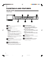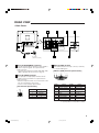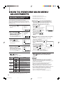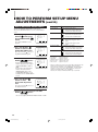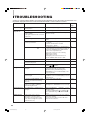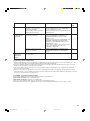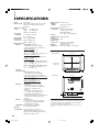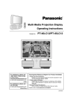
1
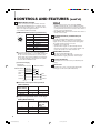
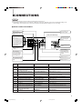
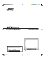
MONITOR
DT-V2000SU
INSTRUCTIONS
For Customer Use:
Enter below the Serial No. which is located on the rear of
the cabinet. Retain this information for future reference.
PHASE
Model No.
Serial No.
LCT0573-001A(6.5J)
:
:
CHROMA
BRIGHT
A
CONTRAST
B
C
ON
OFF
DT-V2000SU
1
DT-V2000SU
MENU
00.12.20, 0:39 PM
VOLUME/ENTER
SELECT
INPUT SELECT
POWER
Thank you for purchasing this JVC DTV monitor. Before using it, read and follow all
instructions carefully to take full advantage of the monitor’s capabilities.
SAFETY PRECAUTIONS
FCC INFORMATION
WARNING :
TO PREVENT FIRE OR SHOCK HAZARDS, DO NOT
EXPOSE THIS MONITOR TO RAIN OR MOISTURE.
CAUTION :
To reduce the risk of electric shock, do not remove cover.
Refer servicing to qualified service personnel.
This monitor is equipped with a 3-blade grounding-type
plug to satisfy FCC rule. If you are unable to insert the
plug into the outlet, contact your electrician.
PRECAUTIONS
● Use only the power source specified on the unit.
(120 V AC, 60 Hz)
● Keep flammable material, water, and metal objects away
from the unit – especially the interior of the unit.
● This unit incorporates high voltage circuitry.
For your own safety and that of your equipment, do not
attempt to modify or disassemble this monitor.
There are no user-serviceable parts inside.
● Unplug the monitor when you’re not going to be using it for a
long period.
CAUTION: Changes or modification not approved by
JVC could void the user’s authority to operate
the equipment.
NOTE: This equipment has been tested and found to
comply with the limits for a Class A digital device,
pursuant to Part 15 of the FCC Rules. These limits are
designed to provide reasonable protection against
harmful interference when the equipment is operated in a
commercial environment. This equipment generates,
uses, and can radiate radio frequency energy and, if not
installed and used in accordance with the instruction
manual, may cause harmful interference to radio
communications. Operation of this equipment in a
residential area is likely to cause harmful interference in
which case the user will be required to correct the
interference at his own expense.
HANDLING
● Avoid shocks or vibrations. These may damage the unit and
cause it to malfunction.
● Do not block the ventilation slots.
● Do not expose this unit to high temperatures.
Extended exposure to direct sunlight or a heater could
deform the cabinet or cause the performance of internal
components to deteriorate.
● Do not place the unit near appliances generating strong
electric or magnetic fields. There can generate picture noise
and instability.
● Keep the monitor clean by wiping the cabinet and CRT
screen with a piece of soft cloth. Do not apply thinner or
benzine. These chemicals can damage the finish and erase
printed letters. When the unit is excessively dirty, use a
diluted neutral cleanser, then wipe away the cleanser with a
dry cloth.
SCREEN BURN
● It is not recommended to keep a certain still image displayed
on screen for a long time as well as displaying extremely
bright images on screen. This may cause a burning (sticking)
phenomenon on the screen of cathode-ray tube. This
problem does not occur as far as displaying normal video
playback motion images.
2
LCT0573-001A(6.5J)
2
00.12.20, 0:39 PM
CONTENTS
SAFETY PRECAUTIONS ............................................................................................... 2
CONTROLS AND FEATURES ....................................................................................... 4
CONNECTIONS ............................................................................................................. 7
HOW TO HANDLE BASIC OPERATIONS ..................................................................... 8
HOW TO PERFORM MAIN MENU ADJUSTMENTS ................................................... 10
HOW TO PERFORM SET-UP MENU ADJUSTMENTS ............................................... 16
TROUBLESHOOTING ................................................................................................. 20
SPECIFICATIONS ........................................................................................................ 22
3
LCT0573-001A(6.5J)
3
00.12.20, 0:39 PM
CONTROLS AND FEATURES
FRONT VIEW
<Front Panel>
2
1
PHASE
CHROMA
BRIGHT
3
4
A
CONTRAST
B
C
ON
OFF
MENU
DT-V2000SU
A
PHASE
CHROMA
BRIGHT
B
VOLUME/ENTER
SELECT
INPUT SELECT
POWER
C
CONTRAST
ON
OFF
MENU
DT-V2000SU
VOLUME/ENTER
SELECT
INPUT SELECT
POWER
7
1 Speaker
6
5
5 INPUT SELECT buttons
A built-in speaker is located in the right panel when the
monitor is viewed from the front.
2 MENU button
Displays and turns off the menu screens.
Notes:
● There are two menu screens: the <MAIN MENU>
screen and the <SET-UP MENU> screen.
● To display the <MAIN MENU> screen, press the MENU
button.
● To display the <SET-UP MENU> screen, when no menu
screen is displayed, press the VOLUME/ENTER (–)
button while pressing the SELECT (∞) button.
● To select an item in a menu screen, press the SELECT
(∞) button.
● To set or adjust a selected item in a menu screen, press
the VOLUME/ENTER (–/+) buttons.
3 SELECT (∞) button
Selects an item in a menu screen. Each time the SELECT
button is pressed, the selection mark moves to the next
item below.
Select the video signal input to each terminal.
Input A button [INPUT A (RGB/COMPO.)]
Selects the video signal input to the INPUT A (RGB/
COMPO.) terminal. When selected, the INPUT A
indicator lights in green.
Input B button [INPUT B (VIDEO)]
Selects the video signal input to the INPUT B (VIDEO)
terminal. When selected, the INPUT B indicator lights
in green.
Input C button [INPUT C (RGB)]
Selects the video signal input to the INPUT C (RGB)
terminal. When selected, the INPUT C indicator lights
in green.
6 VOLUME/ENTER (–/+) buttons
Adjust the speaker volume. Also used to set or adjust an
item in a menu screen.
7 Picture adjustment knobs
Adjust the picture hue (PHASE), chroma (CHROMA),
brightness (BRIGHT) and contrast (CONTRAST).
* For details, refer to page 9.
4 POWER switch/POWER indicator
Monitor power switch and power indicator. Press the
POWER switch to turn the power ON or OFF.
* When the monitor is ON, there is a slight delay before
the picture appears while the monitor runs a self-test.
4
LCT0573-001A(6.5J)
4
00.12.20, 0:39 PM
REAR VIEW
<Rear Panel>
8
9
INPUT A
11
INPUT B
(RGB/COMPO.)
IN
10
(VIDEO)
OUT
IN
Y/C
OUT
G/Y
INPUT A
INPUT B
(RGB/COMPO.)
IN
(VIDEO)
OUT
IN
B/PB
/B-Y
HD/
CS
R/PR
/R-Y
VD
REMOTE
INPUT C
IN/OUT
(RGB)
AUDIO INPUT
EXT SYNC
AC INPUT
B/PB
/B-Y
HD/
CS
INPUT C
R/PR
/R-Y
VD
AUDIO INPUT
EXT SYNC
15
AC outlet
(120 V AC, 60 Hz)
8 INPUT A (RGB/COMPO.) terminals
Input (IN) and output (OUT) terminals for Analog RGB, Y/
R-Y/B-Y component signals. The output terminal is
bridge-connected.
* For details about DTV-format signals (480i, 480p, 720p,
1080i) compatible with this unit, refer to page 23.
(MONO)
12
13
10 INPUT C (RGB) terminal
Input terminal (D-sub 3-row/15-pin connector) exclusively
for computer RGB signals.
[INPUT C (RGB) terminal specifications]
10
9
9 INPUT B (VIDEO) terminals
Video input (IN) and output (OUT) terminals and Y/C
(S-Video) input (Y/C) terminal. The output terminal is
bridge-connected.
* When both Input B terminals are connected at the same
time, the Y/C terminal is given priority.
* There is no Y/C (S-Video) output terminal.
[Y/C terminal specifications]
3
1
15
8
54321
7
6
14 13 12 11
Pin No.
Signal
Pin No.
Signal
1
VIDEO (RED)
9
NC
2
VIDEO (GREEN)
10
GND (SYNC)
Signal
3
VIDEO (BLUE)
11
NC
1
GND (Y)
4
NC
12
NC
2
GND (C)
5
GND
13
H SYNC *1
3
Y
6
GND (RED)
14
V SYNC *1
4
C
7
GND (GREEN)
15
NC
8
GND (BLUE)
Pin No.
Y/C
2
IN/OUT
(RGB)
(MONO)
14
4
REMOTE
Y/C
OUT
G/Y
AC INPUT
*1: Input impedance: low impedance (330 Ω)
5
LCT0573-001A(6.5J)
5
00.12.20, 0:39 PM
CONTROLS AND FEATURES (cont’d.)
Notes:
11 REMOTE IN/OUT terminal
External control input and output terminal. Instead of
using the INPUT SELECT button, an external control
signal changes the INPUT mode. INPUT mode status
data is also output through this terminal.
* The terminal is DIN 8-pin (female).
[REMOTE IN/OUT terminal specifications]
8
7
6
3
Pin No.
Signal
1
REMOTE ENABLE
2
SELECT 1
3
SELECT 2
4
STATUS 1
5
STATUS 2
6
NC
7
GND
8
GND
1
5
2
4
DT-V2000SU
(REMOTE IN/OUT terminal)
SELECT 2 3
External controller
TTL level
Audio input terminal (RCA pin-jack).
* The audio input level is 500 mVrms. Sound becomes
distorted when a signal greater than 1 Vrms is input.
14 AC inlet [AC INPUT]
15 Power cord
Provided power cord for connecting the AC inlet [AC
INPUT] $ to an AC outlet (120 V AC, 60 Hz).
TTL level
TTL level
8
GND
13 AUDIO INPUT terminal
Power input connector. Connect the provided AC power
cord %.
[Connection Image]
SELECT 1 2
12 EXT SYNC terminals (available only for
INPUT A)
Input (IN) and output (OUT) terminals for horizontal
synchronization (HD) or composite synchronization (Cs)
signals, as well as vertical synchronization (VD) signals.
The output terminal is bridge-connected.
* Available only for INPUT A.
* Synchronization signals are automatically detected.
External synchronization is selected when HD/VD or Cs
is input. The priority is as follows: HD/VD > Cs.
To test external control, short-circuit the REMOTE
ENABLE terminal (Pin No. 1) to the GND terminal (Pin
No. 8) so that the external remote control becomes
valid (L level). Then, turn the SELECT 1 terminal (Pin
No. 2) and the SELECT 2 terminal (Pin No. 3) ON to
select the INPUT SELECT mode.
REMOTE ENABLE 1
● To test external control, short-circuit the REMOTE
ENABLE terminal (Pin No. 1) to the GND terminal (Pin
No. 8) so that the external remote control becomes valid
(L level). External control doesn’t function when external
remote control is invalid (H level).
● The POWER SAVE function doesn’t work when external
remote control is valid.
GND
TTL level
STATUS 1 4
TTL level
STATUS 2 5
STATUS 1
STATUS 2
Pin No.
External Control Input in the Input Mode
(INPUT SELECT)
Input mode
(INPUT SELECT)
SELECT 2
SELECT 1
INPUT A
L
L
INPUT B
L
H
INPUT C
H
L
Output of Input Mode Status in the Input
Mode (INPUT SELECT)
STATUS 2
STATUS 1
Input Mode
(INPUT SELECT)
Status Data
Output
L
L
INPUT A
L
H
INPUT B
H
L
INPUT C
6
LCT0573-001A(6.5J)
6
00.12.20, 0:39 PM
CONNECTIONS
Notes:
● Before connecting your system, make sure that all units are turned off.
● The illustration below shows some examples of different connections. Terminal connections may differ depending on the
component(s) connected. Be sure to refer to the instructions provided with the unit(s) you are connecting.
BASIC CONNECTION EXAMPLE
0
!
Bridge output of 9
Unit outputting video
signal
Unit outputting analog
RGB signal
9
or
Unit outputting DTVformat signal
Bridge output of 1,
2 and 3
Unit outputting
horizontal synchronization signal (HD) or
composite synchronization signal (Cs)
[Rear-panel terminals]
1
INPUT A
IN
2
AC INPUT
#
INPUT B
(RGB/COMPO.)
or
Unit outputting Y/R-Y/
B-Y component signal
Unit outputting Y/C
(S-video) signal
(VIDEO)
OUT
IN
Y/C
OUT
G/Y
B/PB
/B-Y
HD/
CS
R/PR
/R-Y
VD
INPUT C
REMOTE
IN/OUT
(RGB)
3
4
External control unit
(for selecting input
mode)
AUDIO INPUT
$
EXT SYNC
Unit outputting audio
signal
(MONO)
@
5
Unit outputting
personal computer
signal (RGB signal
and synchronization
signal)
8
Bridge output of 5
Unit outputting vertical
synchronization signal
(VD)
Caption
Numbers
7
6
Bridge output of 6
Signals
Terminals
Functions
1
2
3
Analog RGB signal
INPUT A (RGB/COMPO.) IN
Analog RGB signal input
Y/R-Y/B-Y component signal
INPUT A (RGB/COMPO.) IN
Y/R-Y/B-Y component signal input
DTV-format signal
(480i, 480p, 720p, 1080i)
INPUT A (RGB/COMPO.) IN
DTV-format signal (480i, 480p, 720p, 1080i) input
4
Analog RGB, Y/R-Y/B-Y component,
DTV-format signal
INPUT A (RGB/COMPO.) OUT
Bridge output of 1, 2 or 3
5
Horizontal synchronization (HD)/
composite synchronization (Cs) signal
EXT SYNC (HD/Cs) IN
Horizontal synchronization (HD) or composite
synchronization (Cs) signal input
6
7
8
Vertical synchronization (VD) signal
EXT SYNC (VD) IN
Vertical synchronization (VD) signal input
Vertical synchronization (VD) signal
EXT SYNC (VD) OUT
Bridge output of 6
Horizontal synchronization (HD)/
composite synchronization (Cs) signal
EXT SYNC (HD/Cs) OUT
Bridge output of 5
9
0
!
@
Video signal
INPUT B (VIDEO) IN
Video signal input
Video signal
INPUT B (VIDEO) OUT
Bridge output of 9
Y/C signal
INPUT B (VIDEO) Y/C IN
Y/C (S-video) signal input
Personal computer signal (RGB signal
and synchronization signal)
INPUT C (RGB) IN
Personal computer signal (RGB signal and
synchronization signal) input
#
External control signal (input mode
selection/ status data output)
REMOTE IN/OUT
Input mode selection (input) and status data output
$
Audio signal
AUDIO INPUT
Audio signal input
* Refer to page 23 for specifications of DTV-format signals (480i, 480p, 720p, 1080i) that can be input.
7
LCT0573-001A(6.5J)
7
00.12.20, 0:39 PM
HOW TO HANDLE BASIC
OPERATIONS
BASIC OPERATION
1. Press the POWER
turn on the power.
switch to
ON
OFF
POWER
Selected Input Display (Mode)
Display
ON (_)
: Power turns ON. (Power indicator lights in
green.)
OFF (—) : Power turns OFF. (Power indicator goes out.)
* The frequency of the input
Input display
signals (or the color system or
DTV format) is automatically
identified and displayed for
about three seconds.
INPUT A(RGB)pInput display
49kHz 75HzpFrequency
( or color system)
display
Frequency
(or color system or
DTV format) display
Input
INPUT A (RGB)
INPUT A (COMPO.) COMPONENT input
INPUT B (VIDEO)
VIDEO input
INPUT B (Y/C)
Y/C input
INPUT C
RGB (PC) input
Input Signal Frequency/Color System/DTV Format
Display
Display
Input signal
NTSC
2. Press the INPUT SELECT
buttons to choose the
input.
A
B
RGB input
NTSC, B/W *1
1080i
HDTV format for DTV
720p
HDTV format for DTV
480p
SDTV format for DTV
C
INPUT SELECT
A : INPUT A input mode
(INPUT A indicator lights in green)
B : INPUT B input mode
(INPUT B indicator lights in green)
C : INPUT C input mode
(INPUT C indicator lights in green)
* When the input mode is changed or the power is turned
on, the selected input and frequency (or color system or
DTV format) are automatically identified and displayed
for about three seconds.
3. Press the VOLUME/ENTER
buttons to adjust the
speaker volume.
VOLUME/ENTER
+ : The built-in speaker volume is increased. (00 [ 50)
– : The built-in speaker volume is decreased. (50 [ 00)
* The screen indication disappears
after about three seconds.
VOLUME : 25
480i
SDTV format for DTV
NO SYNC
No identifiable signal
OO kHz OO Hz
RGB signal at a non-preset frequency
(Current frequency is displayed)
Out of range
Signal outside the frequency range
*1: For B/W signal, f H = 15.75 kHz, f V = 60 Hz.
Input mode and frequency (or color system or DTV
format) display
● The size of the letters in the on-screen indication is automatically adjusted. However, the size of letters at the same
frequency may change due to processing dispersion.
● The “OO kHz OO Hz” indication shown in the table above
appears when the frequency is automatically identified.
The horizontal frequency (kHz) and the vertical frequency
(Hz) are displayed with decimal fractions omitted.
● The indicated frequency may differ from the actual frequency
due to processing dispersion.
● Refer to page 14 “DISPLAY OF PRESENT INPUT STATUS”
for details about the input mode and frequency (or color
system or DTV format) screen.
When the POWER SAVE function is valid (ON)
● When INPUT C is selected, whenever the horizontal and
vertical synchronization signals are no longer detected, the
screen goes out and the POWER indicator blinks (only
when the connected computer has a power
management function conforming to VESA). For details
about the POWER SAVE function, see page 16.
Notes:
● The monitor’s audio input level is 500 mVrms. Sound
becomes distorted when a signal greater than 1 Vrms is
input.
● When a DTV-format signal is displayed, noise may appear
at the bottom of the screen or a signal unrelated to the
picture may appear at the top or bottom. This is not a
malfunction.
8
LCT0573-001A(6.5J)
8
00.12.20, 0:39 PM
OPERATION OF PICTURE ADJUSTMENT KNOBS
PHASE knob
Notes:
Adjusts picture hue.
● The standard position of each knob is the center point
where the knob clicks into place.
The standard position is also indicated in the <PICTURE
ADJ.> menu.
● Adjusting the PHASE knob and CHROMA knob may have
no effect depending on the input signal (input mode).
( : valid – : invalid)
PHASE
greenish
reddish
CHROMA knob
Adjusts picture chroma.
CHROMA
deeper
lighter
B
C
RGB
COMPO.
VIDEO
RGB
PHASE
–
–
CHROMA
–
–
BRIGHT
CONTRAST
BRIGHT knob
Adjusts picture brightness.
BRIGHT
brighter
darker
INPUT SELECT switch
Picture
adjustment
A
CONTRAST knob
Adjusts picture contrast.
CONTRAST
higher
lower
DISPLAY OF MENU SCREENS
There are two menu screens; the <MAIN MENU> screen
and the <SET-UP MENU> screen.
● To display the <MAIN MENU> screen, press the MENU
button.
● To display the <SET-UP MENU> screen, when no menu
MENU
screen is displayed, press the VOLUME/ENTER
button while pressing the SELECT
button.
SELECT
● When a menu screen is displayed, press the menu
/
/
/
shown in the help
operation buttons
indications to select, set, adjust or cancel menu items.
MENU
Notes:
● For details about operating each menu item, refer to pages
10 to 19.
● Items that cannot be set or adjusted in the current input
mode (INPUT SELECT) are not displayed.
● The menu screen automatically disappears when no
operation is performed after about 30 seconds.
● When a prompt appears in the menu screen, it does not
disappear until the operation requested is performed.
SELECT
<MAIN MENU> Screen Example
<SET-UP MENU> Screen Example
Selection mark
Selection mark
<MAIN MENU>
SIZE/POSITION ADJ.
DISTORTION ADJ.
PICTURE ADJ.
FUNCTION SELECT
STATUS
DEGAUSS
EXIT: MENU ENTER: +
SELECT:
Menu title
<SET−UP MENU>
Menu title
Menu items
POWER SAVE :ON
CONTROL LOCK :OFF
STATUS DISPLAY :ON
WHITE BALANCE
all reset
Menu items
Help indications
EXIT: MENU ADJUST: − +
SELECT:
Help indications
9
LCT0573-001A(6.5J)
9
00.12.20, 0:39 PM
HOW TO PERFORM MAIN MENU
ADJUSTMENTS
ADJUSTMENT OF SCREEN SIZE
AND SCREEN POSITION
•
•
•
•
H SIZE: adjusts the horizontal screen size
H POSITION: adjusts the horizontal screen position
V SIZE: adjusts the vertical screen size
V POSITION: adjusts the vertical screen position
You can adjust the screen size and screen position.
This function can be set when an INPUT A component (COMPO.)
signal or INPUT B (VIDEO) signal is input with the underscan size
(UNDER) selected or when an INPUT A RGB signal or INPUT C PC
(RGB) signal is input.
SELECTING [ sub menu] IN PROCEDURE 4
You can also adjust items in procedure 5 with only the
selected item displayed. Use this if the full menu screen
makes it difficult to observe the monitor image.
1 Press the MENU
1 Select the [ sub menu] item in procedure 4.
2 Press the VOLUME/
button.
<MAIN MENU>
MENU
SIZE/POSITION ADJ.
DISTORTION ADJ.
PICTURE ADJ.
FUNCTION SELECT
STATUS
DEGAUSS
The <MAIN MENU> screen
appears.
EXIT: MENU ENTER: +
SELECT:
<MAIN MENU> screen
ENTER
button.
The <sub menu> screen appears.
(A single item is displayed at a
time.)
3 Press the SELECT button to
select the desired item.
4 Perform adjustment with the
VOLUME/ENTER
/
buttons.
H SIZE :+00
−
+
SELECT
2 Press the SELECT
<MAIN MENU>
SELECT
button to select the [SIZE/
POSITION ADJ.] item.
The selection mark ( 4) moves to
the [SIZE/POSITION ADJ.] item.
3 Press the VOLUME/
ENTER
button.
SIZE/POSITION ADJ.
DISTORTION ADJ.
PICTURE ADJ.
FUNCTION SELECT
STATUS
DEGAUSS
EXIT: MENU ENTER: +
SELECT:
<MAIN MENU> screen
<SIZE/POSITION ADJ.>
The <SIZE/POSITION ADJ.>
screen appears.
H SIZE :+01
H POSITION : 00
V SIZE :−07
V POSITION :+02
sub menu
reset
EXIT: MENU ADJUST: − +
SELECT:
<SIZE/POSITION ADJ.> screen
4 Press the SELECT
button to select the
desired adjustment item.
The selection mark ( 4) moves to
SELECT
<SIZE/POSITION ADJ.>
H SIZE :+01
H POSITION : 00
V SIZE :−07
V POSITION :+02
sub menu
reset
SELECT:
<SIZE/POSITION ADJ.> screen
5 Perform adjustment with the VOLUME/ENTER
/
buttons.
* Adjustable range: –80 — +80 *1
VOLUME/ENTER
buttons
H SIZE
(
(
Shifts the screen to the left
(–80 p +80)
)
Shifts the screen to the right
(–80 [ +80)
V SIZE
(
Reduces the screen size vertically
(–80 p +80)
)
Expands the screen size vertically
(–80 [ +80)
V POSITION
(
Contents
Expands the screen size horizontally
(–80 [ +80) *1
H POSITION
Shifts the screen down
(–80 p +80)
)
1 Select the [ reset] item in procedure 4.
2 Press the VOLUME/ENTER
button.
The <reset> screen appears.
3 Perform adjustment with the
VOLUME/ENTER
the MENU button.
Shifts the screen up
(–80 [ +80)
MENU
<reset> screen
button… Values are reset.
VOLUME/ENTER
MENU button … Reset is aborted
(values are unchanged).
* The screen from procedure 4 reappears.
6 After adjustment is complete, press the
MENU button twice to exit the menu
screen.
Notes:
● The [SIZE/POSITION ADJ.] item may not be displayed
depending on which input mode (INPUT SELECT) is
selected. In this case, adjusting the screen size and screen
position may be impossible.
● The menu screen automatically disappears when no
operation is performed after about 30 seconds.
● When a prompt appears in the menu screen, it does not
disappear until the operation requested is performed.
● Up to 12 different RGB signals input to INPUT A or INPUT C
are automatically stored in memory (User Memory).
When the 13th signal is input, the signal first stored in
memory is replaced with the new one.
(Refer to “User Memory for RGB Input” on page 14.)
10
10
Are you sure?
+
“YES“ then key.
MENU
“NO“ then key.
button or
*1: When INPUT A component (COMPO.) or INPUT B (VIDEO) is selected as
the input mode and the [FUNCTION SELECT] item SCAN SIZE is set to
“underscan (UNDER)”, the H SIZE adjustable range is 00 — +80.
LCT0573-001A(6.5J)
<reset>
MENU
Reduces the screen size horizontally
(–80 p +80) *1
)
RESETTING ITEMS TO THEIR FACTORY-SET (INITIAL)
VALUES
You can reset <SIZE/POSITION ADJ.> items to their
factory-set (initial) values.
MENU
EXIT: MENU ADJUST: − +
the selected adjustment item.
Items
<sub menu> screen
00.12.20, 0:39 PM
•
•
•
•
PICTURE DISTORTION
ADJUSTMENT
You can adjust the picture distortion.
This function can be set when an INPUT A component (COMPO.)
signal or INPUT B (VIDEO) signal is input with the underscan size
(UNDER) selected or when an INPUT A RGB signal or INPUT C PC
(RGB) signal is input.
1 Press the MENU
button.
The <MAIN MENU> screen appears.
SIZE/POSITION ADJ.
DISTORTION ADJ.
PICTURE ADJ.
FUNCTION SELECT
STATUS
DEGAUSS
EXIT: MENU ENTER: +
SELECTING [ sub menu] IN PROCEDURE 4
You can also adjust items in procedure 5 with only the
selected item displayed. Use this if the full menu screen
makes it difficult to observe the monitor image.
1 Select the [ sub menu] item in procedure 4.
2 Press the VOLUME/
<MAIN MENU>
MENU
PINCUSHION: adjusts the pincushion distortion
PIN. BALANCE: adjusts the balance of the pincushion distortion
PARALLELOGRAM: adjusts the parallelogram distortion
TRAPEZOID: adjusts the trapezoid distortion
SELECT:
<MAIN MENU> screen
button.
ENTER
The <sub menu> screen appears.
(A single item is displayed at a
time.)
3 Press the SELECT button to
select the desired item.
4 Perform adjustment with the
VOLUME/ENTER
/
buttons.
PINCUSHION :+01
−
+
SELECT
2 Press the SELECT
button to select the
[DISTORTION ADJ.] item.
The selection mark ( 4) moves to
<MAIN MENU>
SELECT
the [DISTORTION ADJ.] item.
SIZE/POSITION ADJ.
DISTORTION ADJ.
PICTURE ADJ.
FUNCTION SELECT
STATUS
DEGAUSS
EXIT: MENU ENTER: +
SELECT:
<MAIN MENU> screen
3 Press the VOLUME/
ENTER
button.
<DISTORTION ADJ.>
The <DISTORTION ADJ.> screen
appears.
PINCUSHION :+05
PIN. BALANCE : 00
PARALLELOGRAM :−01
TRAPEZOID :+02
sub menu
reset
SELECT:
<DISTORTION ADJ.> screen
SELECT
the adjustment item.
/
MENU
PINCUSHION :+05
PIN. BALANCE : 00
PARALLELOGRAM :−01
TRAPEZOID :+02
sub menu
reset
EXIT: MENU ADJUST: − +
SELECT:
<DISTORTION ADJ.> screen
VOLUME/ENTER
buttons
PINCUSHION
(
(
Contents
Swells both horizontal sides of the picture
(–60 [ +60)
PIN. BALANCE
Indents the right side of the picture and
swells the left side of the picture
(–60 p +60)
)
Indents the left side of the picture and
swells the right side of the picture
(–60 [+60)
PARALLELOGRAM
(
Moves the upper side of the picture to
the left and the lower side of the picture
to the right
(–60 p +60)
)
MENU
6 After adjustment is complete, press the
MENU button twice to exit the menu
screen.
Notes:
Indents both horizontal sides of the picture
(–60 p +60)
)
<reset> screen
button… Values are reset.
VOLUME/ENTER
MENU
button… Reset is aborted
(values are unchanged).
* The screen from procedure 4 reappears.
MENU
buttons.
* Adjustable range: –60 — +60
Items
Are you sure?
+
“YES“ then key.
MENU
“NO“ then key.
<DISTORTION ADJ.>
5 Perform adjustment with the VOLUME/
ENTER
RESETTING ITEMS TO THEIR FACTORY-SET (INITIAL)
VALUES
You can reset the <DISTORTION ADJ.> items to their
factory-set (initial) values.
1 Select the [ reset] item in procedure 4.
2 Press the VOLUME/ENTER
button.
The <reset> screen appears.
3 Perform adjustment with the
VOLUME/ENTER
button or
button.
the MENU
<reset>
EXIT: MENU ADJUST: − +
4 Press the SELECT
button to select
the desired adjustment
item.
The selection mark ( 4) moves to
<sub menu> screen
● The [DISTORTION ADJ.] item may not be displayed
depending on which input mode (INPUT SELECT) is
selected. In this case, adjusting the picture distortion may be
impossible.
● The menu screen automatically disappears when no
operation is performed after about 30 seconds.
● When a prompt appears in the menu screen, it does not
disappear until the operation requested is performed.
● Up to 12 different RGB signals input to INPUT A or INPUT C
are automatically stored in memory (User Memory).
When the 13th signal is input, the signal first stored in
memory is replaced with the new one.
(Refer to “User Memory for RGB Input” on page 14.)
Moves the upper side of the picture to
the right and the lower side of the
picture to the left
(–60 [ +60)
TRAPEZOID
(
Shortens the upper side of the picture
(–60 p +60)
)
Expands the upper side of the picture
(–60 [ +60)
11
LCT0573-001A(6.5J)
11
00.12.20, 0:39 PM
HOW TO PERFORM MAIN MENU
ADJUSTMENTS (cont’d.)
PICTURE ADJUSTMENT
You can adjust the picture contrast, brightness, etc.
1 Press the MENU
button.
MENU
The <MAIN MENU> screen appears.
<MAIN MENU>
SIZE/POSITION ADJ.
DISTORTION ADJ.
PICTURE ADJ.
FUNCTION SELECT
STATUS
DEGAUSS
EXIT: MENU ENTER: +
SELECT:
<MAIN MENU> screen
2 Press the SELECT
button to select the
[PICTURE ADJ.] item.
The selection mark ( 4) moves to
<MAIN MENU>
SELECT
the [PICTURE ADJ.] item.
SIZE/POSITION ADJ.
DISTORTION ADJ.
PICTURE ADJ.
FUNCTION SELECT
STATUS
DEGAUSS
EXIT: MENU ENTER: +
SELECT:
<MAIN MENU> screen
3 Press the VOLUME/
ENTER
button.
INPUT A(COMPO)
<PICTURE ADJ.>
CONTRAST :+15
BRIGHT : 00
CHROMA :−05
PHASE :+01
APERTURE :+13
sub menu
reset
The <PICTURE ADJ.> screen
appears.
EXIT: MENU ADJUST: − +
SELECT:
<PICTURE ADJ.> screen
4 Press the SELECT
button to select
the desired adjustment
item.
The selection mark ( 4) moves to
SELECT
the adjustment item.
SELECTING [ sub menu] IN PROCEDURE 4
You can also adjust items in procedure 5 with only the
selected item displayed. Use this if the full menu screen
makes it difficult to observe the monitor image.
1 Select the [ sub menu] item in procedure 4.
2 Press the VOLUME/
ENTER
button.
The <sub menu> screen appears.
(A single item is displayed at a
time.)
3 Press the SELECT button to
select the desired item.
4 Perform adjustment with the
/
VOLUME/ENTER
buttons.
CONTRAST :+07
−
+
− +
SELECT
<sub menu> screen
RESETTING ITEMS TO THEIR FACTORY-SET (INITIAL)
VALUES
You can reset the <PICTURE ADJ.> items to their factoryset (initial) values.
1 Select the [ reset] item in procedure 4.
2 Press the VOLUME/ENTER
button.
The <reset> screen appears.
3 Perform adjustment with the
VOLUME/ENTER
button or
the MENU
button.
<reset>
INPUT A(COMPO)
<PICTURE ADJ.>
CONTRAST :+15
BRIGHT : 00
CHROMA :−05
PHASE :+01
APERTURE :+13
sub menu
reset
EXIT: MENU ADJUST: − +
SELECT:
<PICTURE ADJ.> screen
Are you sure?
+
“YES“ then key.
MENU
“NO“ then key.
<reset> screen
MENU
button… Values are reset.
VOLUME/ENTER
MENU
button… Reset is aborted
(values are unchanged).
* The screen from procedure 4 reappears.
MENU
5 Perform adjustment with the VOLUME/
ENTER
/
buttons.
* Items not displayed because of the selected input mode
(INPUT SELECT) cannot be adjusted.
* Adjustable range: –20 — +20
Items
VOLUME/ENTER
buttons
CONTRAST
(
(
Brightness becomes darker
(–20 p +20)
)
Brightness becomes brighter
(–20 [ +20)
CHROMA
(
Chroma becomes lighter
(–20 p +20)
)
Chroma becomes deeper
(–20 [ +20)
PHASE
(
Phase becomes more reddish
(–20 p +20)
)
Phase becomes more greenish
(–20 [ +20)
APERTURE
(
Notes:
Contrast becomes higher
(–20 [ +20)
BRIGHT
)
MENU
Contents
Contrast becomes lower
(–20 p +20)
)
6 After adjustment is complete, press the
MENU button twice to exit the menu
screen.
● The menu screen automatically disappears when no
operation is performed after about 30 seconds.
● When adjusting the picture, set each picture adjustment
knob on the front panel to the center position
(the knob clicks into place).
● It is possible to memorize the preset picture adjustment for
each video input (up to 3 inputs).
● Items not displayed because of the selected input mode
(INPUT SELECT) cannot be adjusted. In this case, it is also
impossible to perform adjustment with picture adjustment
knobs. (: adjustable –: not adjustable)
Picture
adjustment
INPUT SELECT Button
INPUT A
RGB
COMPO.
VIDEO
RGB (PC)
CONTRAST
Outline becomes clearer
(–20 [ +20)
BRIGHT
CHROMA
–
–
PHASE
–
–
APERTURE
–
–
• PHASE: adjusts the picture phase
• APERTURE: adjusts the picture
aperture (outline)
12
12
INPUT C
Outline becomes more obscure
(–20 p +20)
• CONTRAST: adjusts the picture contrast
• BRIGHT: adjusts the picture brightness
• CHROMA: adjusts the picture chroma
LCT0573-001A(6.5J)
INPUT B
00.12.20, 0:39 PM
FUNCTION SELECTION (SETTING)
You can select (set) the display’s functions.
1 Press the MENU
button.
<MAIN MENU>
MENU
SIZE/POSITION ADJ.
DISTORTION ADJ.
PICTURE ADJ.
FUNCTION SELECT
STATUS
DEGAUSS
The <MAIN MENU> screen appears.
EXIT: MENU ENTER: +
SELECT:
<MAIN MENU> screen
2 Press the SELECT
button to select the
[FUNCTION SELECT] item.
The selection mark ( 4) moves to
<MAIN MENU>
SELECT
SIZE/POSITION ADJ.
DISTORTION ADJ.
PICTURE ADJ.
FUNCTION SELECT
STATUS
DEGAUSS
the [FUNCTION SELECT] item.
EXIT: MENU ENTER: +
SELECT:
<MAIN MENU> screen
3 Press the VOLUME/
ENTER
button.
<FUNCTION SELECT>
RGB/COMPO. :RGB
SCAN SIZE :OVER
ASPECT :4−3
COLOR SW :ON
COLOR TEMP. :HIGH*
reset
The <FUNCTION SELECT> screen
appears.
EXIT: MENU ADJUST: − +
<FUNCTION SELECT>
SELECT
RGB/COMPO. :RGB
SCAN SIZE :OVER
ASPECT :4−3
COLOR SW :ON
COLOR TEMP. :HIGH*
reset
EXIT: MENU ADJUST: − +
SELECT:
<FUNCTION SELECT> screen
5 Perform adjustment with the VOLUME/
/
buttons.
* Items not displayed because of the selected input mode
(INPUT SELECT) cannot be adjusted.
Items
RESETTING ITEMS TO THEIR FACTORY-SET (INITIAL)
VALUES
You can reset each item (RGB/COMPO., SCAN SIZE,
ASPECT COLOR SW and COLOR TEMP.) in the
<FUNCTION SELECT> menu to their factory-set (initial)
values.
1 Select the [ reset] item in procedure 4.
2 Press the VOLUME/ENTER
button.
The <reset> screen appears.
3 Perform adjustment with the
VOLUME/ENTER
button or
button.
the MENU
<reset>
Are you sure?
+
“YES“ then key.
MENU
“NO“ then key.
MENU
<reset> screen
button… Values are reset.
VOLUME/ENTER
MENU
button… Reset is aborted
(values are unchanged).
* The screen from procedure 4 reappears.
MENU
6 After adjustment is complete, press the
MENU button twice to exit the menu
screen.
MENU
4 Press the SELECT
button to select
the desired adjustment
item.
The selection mark ( 4) moves to
ENTER
RGB/COMPO. : sets the input signal of the INPUT A terminal
SCAN SIZE
: sets the scan size
ASPECT
: sets the aspect ratio
COLOR SW : sets the color switch
COLOR TEMP. : sets the color temperature
SELECT:
<FUNCTION SELECT> screen
the adjustment item.
•
•
•
•
•
Contents
Sets the input signal of the INPUT A terminal to receive
RGB or component (COMPO.) signals.
(RGB p[COMPO.)
RGB
: RGB signal is selected.
COMPO. : component signal is selected.
SCAN SIZE
Sets the scan size when component (COMPO.) signals
are input to the INPUT A terminal.
(OVER p[UNDER)
p
p
RGB/COMPO.
OVER
: standard scan size (95% overscan) is
selected.
UNDER : underscan size is selected.
ASPECT
Sets the aspect ratio for INPUT B signals and INPUT A
component (480i, 480p) signals.
(4-3 p[ 16-9)
4-3 : sets the aspect ratio to 4:3. (Standard for INPUT B
signals.)
16-9 : sets the aspect ratio to 16:9. (Standard for INPUT A
component (480i, 480p) signals.)
COLOR SW
Sets the color switch of the INPUT B signal input and the
INPUT A component (COMPO.) signal input.
(ONp[ OFF)
ON : usually keep COLOR SW set to ON (the picture is
colored).
OFF : the colored picture becomes black and white.
COLOR TEMP.
Sets the color temperature to HIGH or LOW
(HIGH p[ LOW).
HIGH : sets the color temperature to HIGH.
LOW : sets the color temperature to LOW.
Notes:
● The menu screen automatically disappears when no
operation is performed after about 30 seconds.
● When a prompt appears in the menu screen, it does not
disappear until the operation requested is performed.
● Before setting functions, make sure that signals are being
input to the monitor.
● Items that cannot be set or adjusted because of the
selected input mode (INPUT SELECT) are not displayed.
● When setting the [RGB/COMPO.] item, procedure 6 is not
needed. After being set, the picture temporarily disappears,
then the function selection is complete.
● The [SCAN SIZE] item can be set only when INPUT B
(NTSC composite or Y/C) signals or INPUT A component
signals are input.
● The [ASPECT] item can be set only when INPUT B signals
or INPUT A component signals (480i, 480p) are input. With
INPUT B signals, 4:3 (4-3) is the standard. With INPUT A
(COMPO.) signals, 16:9 (16-9) is the standard.
● The [COLOR SW] item can be set only when INPUT B
signals or INPUT A component signals are input.
● When the “ * ” mark appears after the [COLOR TEMP.]
setting is changed (HIGH or LOW), it means that the
[WHITE BALANCE] item in the <SET-UP MENU> screen
has been adjusted. [WHITE BALANCE] is different for
[HIGH] and [LOW].
13
LCT0573-001A(6.5J)
13
00.12.20, 0:39 PM
HOW TO PERFORM MAIN MENU
ADJUSTMENTS (cont’d.)
Connection Between Input Mode Display and
Frequency (or Color System or DTV Format) Display
DISPLAY OF PRESENT INPUT
STATUS
You can see the present status of the input mode and frequency
(or color system or DTV format). The status display disappears
after three seconds.
This function is available with all input signals.
1 Press the MENU
button.
MENU
The <MAIN MENU> screen appears.
Input
Mode
Input
Signal
Frequency,
Input Mode
Color System or Display
DTV Format
Signal
Frequency,
Color
System or
DTV Format
Display
INPUT
A
RGB
Signal within the
frequency range
OOkHz OOHz
<MAIN MENU>
SIZE/POSITION ADJ.
DISTORTION ADJ.
PICTURE ADJ.
FUNCTION SELECT
STATUS
DEGAUSS
EXIT: MENU ENTER: +
SELECT
SIZE/POSITION ADJ.
DISTORTION ADJ.
PICTURE ADJ.
FUNCTION SELECT
STATUS
DEGAUSS
SELECT:
<MAIN MENU> screen
3 Press the VOLUME/
ENTER
button.
INPUT
B
VIDEO
INPUT A(RGB)
49kHz 75Hz
The <STATUS> screen appears.
The present input mode and
frequency (or color system or DTV
format) appears.
NO SYNC
Signal outside the
frequency range
Out of range
480p (31 kHz 60 Hz)
480p
1080i (33 kHz 60 Hz)
1080i
720p (45 kHz 60 Hz)
720p
Other signal
720p
Signal without
synchronization
NO SYNC
Signal outside the
frequency range
Out of range
<MAIN MENU>
EXIT: MENU ENTER: +
the [STATUS] item.
Signal without
synchronization
COMPONENT 480i (15 kHz 60 Hz) INPUT A (COMPO.) 480i
SELECT:
<MAIN MENU> screen
2 Press the SELECT
button to select the
[STATUS] item.
The selection mark ( 4) moves to
INPUT A (RGB)
Y/C
<STATUS> screen
INPUT A (RGB) pInput mode
49 kHz 75 Hz pFrequency (or color system or DTV
format)
INPUT
C
RGB (PC)
NTSC
INPUT B (VIDEO) NTSC
Signal without
synchronization
NO SYNC
Signal outside the
frequency range
(except for NTSC)
Out of range
NTSC
INPUT B (Y/C)
NTSC
Signal without
synchronization
NO SYNC
Signal outside the
frequency range
(except for NTSC)
Out of range
Signal within the
frequency range
INPUT C
OOkHz OOHz
* The <STATUS> screen indication automatically
disappears after about three seconds.
Signal without
synchronization
NO SYNC
Signal outside the
frequency range
Out of range
Notes:
● When the input signal cannot be detected, the message
“NO SYNC” is displayed.
● The present frequency (or color system or DTV format) is
detected and displayed. The horizontal (kHz) and vertical
(Hz) frequencies are displayed with decimal fractions omitted.
● The frequency displayed may differ from the actual frequency
due to processing dispersion.
• [OOkHz OOHz] shown in the table displays the present frequency
detected.
• The horizontal (kHz) and vertical (Hz) frequencies are displayed with
decimal fractions omitted.
• The frequency displayed may differ from the actual frequency due to
processing dispersion.
User Memory for RGB Input
● The RGB signals input to INPUT A or INPUT C may require
some adjustments, depending on the signal’s characteristics.
If necessary, perform the required adjustments referring to
“How to Perform Main Menu Adjustments” on pages 10 – 11.
The adjusted contents are automatically stored in memory
(User Memory).
When a signal corresponding to one stored in the User
Memory is input, the stored adjustment contents are recalled.
This unit stores the adjusted contents of up to 12 different
signals in memory.
When the 13th signal is input, the signal first stored in
memory is replaced (overwritten) by the new one. (The
contents stored first are replaced first.)
14
LCT0573-001A(6.5J)
14
00.12.20, 0:39 PM
Recommended Input Mode List
Resolution
Horizontal Vertical
*
*
*
*
*
*
*
*
DEGAUSSING THE SCREEN
Horizontal
Frequency
(kHz)
Vertical
Frequency
(Hz)
Preset
NTSC
786
243
15.73
29.97 (i)
480i
720
244
15.73
29.97 (i)
480p
720
483
31.469
59.94
720p
1280
720
44.955
59.94
1080i
1920
540
33.75
30.00 (i)
VGA480
640
480
31.47
59.94
VESA600A
(S-VGA)
800
600
35.16
56.26
MAC16
832
624
49.41
74.52
VESA768B
(S-VGA)
1024
768
56.47
70.06
VGA350
640
350
31.47
70.08
If the monitor is placed too close to a speaker or other device
incorporating a magnet, or if it is moved with the power on,
irregular color may appear on the screen. If this happens,
activate the degaussing circuit to degauss the picture. This
circuit will remove the irregular color from the screen.
1 Press the MENU
button.
<MAIN MENU>
MENU
The <MAIN MENU> screen appears.
SIZE/POSITION ADJ.
DISTORTION ADJ.
PICTURE ADJ.
FUNCTION SELECT
STATUS
DEGAUSS
EXIT: MENU ENTER: +
SELECT:
<MAIN MENU> screen
VGA400
640
400
31.47
70.08
S-VGA
800
600
48.08
72.19
8514A
1024
384
35.52
43.48 (i)
VESA400
640
400
37.88
83.43
VESA480
640
480
37.88
72.84
VESA600B
800
600
37.88
60.32
VESA600C
800
600
48.08
72.19
VESA768A
1024
768
48.38
60.02
MAC2
(MAC13)
640
480
35.00
66.67
S-MAC
(MAC19)
1024
768
48.78
59.56
The “” symbol indicates factory-set modes.
The “” symbol indicates recommended timing modes.
The “(i)” symbol indicates interlacing.
Macintosh™ and Power Macintosh™ are registered trademarks
owned by Apple Computer Inc. (America).
IBM® and VGA are registered trademarks owned by International
Business Corporation (America).
VESA® is a registered trademark owned by Video Electronics
Standard Association.
Windows® is a registered trademark owned by Microsoft Corporation
in America and other countries.
All other product names are the brands or the registered trademarks
of their respective holders.
2 Press the SELECT
button to select the
[DEGAUSS] item.
The selection mark ( 4) moves to
SELECT
the [DEGAUSS] item.
<MAIN MENU>
SIZE/POSITION ADJ.
DISTORTION ADJ.
PICTURE ADJ.
FUNCTION SELECT
STATUS
DEGAUSS
EXIT: MENU ENTER: +
SELECT:
<MAIN MENU> screen
3 Press the VOLUME/
ENTER
button.
The degaussing circuit is activated
and the <DEGAUSS> screen
appears.
U
Mode
Degaussing!
<DEGAUSS> screen
* The <DEGAUSS> screen indication automatically
disappears after about three seconds, and degaussing
is complete after about 10 seconds.
Notes:
Notes:
● The input modes shown in the table above are recommended.
● When using signals that do not conform to any factory-set
signal mode, you should adjust the width or position of the
picture horizontally or vertically as required.
For details about adjustment, refer to pages 10 and 11,
“HOW TO PERFORM MAIN MENU ADJUSTMENTS.”
● When the power of the monitor is turned on, the degaussing
circuit is automatically activated.
● Do not place a floppy disk or credit card close to the
monitor. The magnetic field generated by the monitor may
erase its contents.
● When degaussing the screen by manually activating the
degaussing circuit, wait more than 30 minutes to gain the
best effect. (The shorter the interval is, the less effective
degaussing is.)
15
LCT0573-001A(6.5J)
15
00.12.20, 0:39 PM
HOW TO PERFORM SET-UP MENU
ADJUSTMENTS
POWER SAVE FUNCTION SETTING
This monitor has a power save function. For example, if the
power is turned on with no signal input or the signal input is no
longer detected, the power save function puts the monitor into
signal-waiting mode (the screen goes out).
The power save function is set in the <SET-UP MENU> screen.
The power save function is available only with INPUT C signals and
only when the monitor is connected to a computer which has a power
management function that conforms to the VESA standard.
1 While pressing the
SELECT
button, press
SELECT
the VOLUME/ENTER
button.
<SET−UP MENU>
POWER SAVE :ON
CONTROL LOCK :OFF
STATUS DISPLAY :ON
WHITE BALANCE
all reset
EXIT: MENU ADJUST: − +
The <SET-UP MENU> screen
appears.
2 Press the SELECT
button to select the
[POWER SAVE] item.
The selection mark ( 4) moves to
SELECT:
<SET-UP MENU> screen
<SET−UP MENU>
SELECT
the [POWER SAVE] item.
POWER SAVE :ON
CONTROL LOCK :OFF
STATUS DISPLAY :ON
WHITE BALANCE
all reset
EXIT: MENU ADJUST: − +
POWER SAVE FUNCTION
How the Power Save Function Operates
● Horizontal synchronization signal vanishes.
≠
The “NO SYNC” indication is displayed and about 10
seconds later the “POWER SAVE” indication is displayed
(for about 15 seconds).
≠
The monitor enters standby mode.
(When the horizontal synchronization signal is detected
again, the monitor resumes normal operation (the picture
reappears).)
● Horizontal/vertical synchronization signals vanish.
≠
The “NO SYNC” indication is displayed and 10 seconds
later the “POWER SAVE” indication is displayed (for about
15 seconds).
≠
The monitor enters suspended mode.
(When the horizontal/vertical synchronization signals are
detected again, the monitor resumes normal operation (the
picture is displayed) after about 10 –15 seconds.)
SELECT:
<SET-UP MENU> screen
3 Perform adjustment with the VOLUME/
ENTER
/
buttons.
ON : The power save function is turned on.
OFF : The power save function is turned off.
4 After adjustment is complete, press the
button to exit the menu screen.
MENU
MENU
The following shows the power indicator lighting and power
consumption savings when the power save function is
used.
Power Save Function
Mode
Power
Consumption
Power
Indicator (
Notes:
● The power save function is available only with INPUT C
signals and only when the monitor is connected to a
computer which has a power management function that
conforms to the VESA standard.
● The power save function cannot be set when the [POWER
SAVE] item is not displayed, such as when the selected
input mode (INPUT SELECT) is INPUT A or INPUT B.
● Items that cannot be set or adjusted in the current input
mode (INPUT SELECT) are not displayed.
● When external remote control is activated, the power save
function is turned off.
● The power save function factory-set value is “ON.”
Normal
Mode
Standby
Mode
Suspended
Mode
100%
Less than
about 90%
Less than
about 30%
Lit
Lit
Shift Time
from Normal
Mode
—
About 15
seconds
About 15
seconds
Return Time
to Normal
Mode
—
Immediate
About 10 to
15 seconds
Note:
To exit from the power save mode, perform one of the
following. (Note: if the operating conditions are the same as
what they were in the power save mode, the power save
mode will be reactivated after about 30 seconds.)
• Input signals (vertical/horizontal synchronization signals)
from the computer to the monitor correctly,
• Cancel the power save mode by operating the computer,
• Operate the control buttons on the front of the monitor,
• Disconnect the power cord from the AC outlet and reconnect
it.
16
LCT0573-001A(6.5J)
16
Blinks
)
00.12.20, 0:39 PM
CONTROL LOCK OF BUTTONS
AND KNOBS
You can set the CONTROL LOCK function to disable control
buttons and knobs on the front panel, except for the power
switch.
This function is set in the <SET-UP MENU> screen.
1 While pressing the
SELECT
button, press
SELECT
the VOLUME/ENTER
button.
2 Press the SELECT
button to select the
[CONTROL LOCK] item.
The selection mark ( 4) moves to
SELECT
the [CONTROL LOCK] item.
1 While pressing the
POWER SAVE :ON
CONTROL LOCK :OFF
STATUS DISPLAY :ON
WHITE BALANCE
all reset
SELECT:
<SET-UP MENU> screen
<SET−UP MENU>
POWER SAVE :ON
CONTROL LOCK :OFF
STATUS DISPLAY :ON
WHITE BALANCE
all reset
EXIT: MENU ADJUST: − +
SELECT:
* When the <SET-UP MENU> screen is <SET-UP MENU> screen
displayed with the CONTROL LOCK
function turned on, the selection mark (4) appears where
the [CONTROL LOCK] item is displayed. In this case, the
selection mark (4) cannot be moved to other items.
3 Perform adjustment with the VOLUME/
ENTER
/
This function (STATUS DISPLAY) is set in the <SET-UP MENU>
screen.
<SET−UP MENU>
<SET−UP MENU>
EXIT: MENU ADJUST: − +
The <SET-UP MENU> screen
appears.
SETTING DISPLAY OF PRESENT
INPUT STATUS WHEN INPUT IS
TURNED ON/OFF
buttons.
ON : Control of front panel functions is turned off.
OFF : Control of front panel functions is turned on.
4 After adjustment is complete, press the
button to exit the menu screen.
MENU
MENU
* The screen automatically disappears after about 30 seconds
if the MENU button is not pressed to exit the menu screen.
Notes:
● When the CONTROL LOCK function is turned on, if control
knobs or buttons on the front panel (except for the power
switch) are operated, “Control lock on!” is displayed for
about three seconds.
● When the <SET-UP MENU> screen is displayed with the
CONTROL LOCK function turned on, the selection mark (4)
appears where the [CONTROL LOCK] item is displayed. In
this case, the selection mark (4) cannot be moved to other
items.
● When the CONTROL LOCK function is turned on, other
menu screens cannot be displayed.
(The CONTROL LOCK function is effective from the
moment it is switched “ON.”)
● Items that cannot be set or adjusted in the current input
mode (INPUT SELECT) are not displayed.
button, press
SELECT
SELECT
the VOLUME/ENTER
button.
POWER SAVE :ON
CONTROL LOCK :OFF
STATUS DISPLAY :ON
WHITE BALANCE
all reset
EXIT: MENU ADJUST: − +
The <SET-UP MENU> screen
appears.
2 Press the SELECT
button to select the
[STATUS DISPLAY] item.
The selection mark ( 4) moves to
SELECT:
<SET-UP MENU> screen
<SET−UP MENU>
SELECT
the [STATUS DISPLAY] item.
POWER SAVE :ON
CONTROL LOCK :OFF
STATUS DISPLAY :ON
WHITE BALANCE
all reset
EXIT: MENU ADJUST: − +
SELECT:
<SET-UP MENU> screen
3 Perform adjustment with the VOLUME/
ENTER
/
buttons.
ON : The present input status is displayed when the input
is changed.
OFF : The present input status is not displayed when the
input is changed.
4 After adjustment is complete, press the
button to exit the menu screen.
MENU
MENU
* The screen automatically disappears after about 30 seconds
if the MENU button is not pressed to exit the menu screen.
Notes
Items that cannot be set or adjusted in the current input mode
(INPUT SELECT) are not displayed.
<STATUS DISPLAY> Screen
● Press the INPUT SELECT
buttons to select the input.
The present input status is
displayed on the <STATUS
DISPLAY> screen.
INPUT A(RGB)
49kHz 75Hz
(Example)
<STATUS DISPLAY> screen
INPUT A (RGB) pInput mode
49 kHz 75 Hz pFrequency (or color system or DTV
format)
* The screen indication automatically disappears after
about three seconds.
Note:
The displayed contents are the same as in “DISPLAY OF
PRESENT INPUT STATUS” on page 14. Refer to that
section for more details. Also, refer to “Notes” and
“Connection Between Input Mode Display and Frequency
(or Color System or DTV Format) Display” on page 14.
17
LCT0573-001A(6.5J)
17
00.12.20, 0:39 PM
HOW TO PERFORM SET-UP MENU
ADJUSTMENTS (cont’d.)
Items
WHITE BALANCE ADJUSTMENT
Contents
BLUE DRIVE
Adjusts the blue drive level.
… Decreases the blue drive level.
… Increases the blue drive level.
RED DRIVE
Adjusts the red drive level.
… Decreases the red drive level.
… Increases the red drive level.
You can set (adjust) the white balance of the screen.
This function (WHITE BALANCE) is set in the <SET-UP MENU>
screen.
1 While pressing the
SELECT
button, press
SELECT
the VOLUME/ENTER
button.
The <SET-UP MENU> screen
appears.
2 Press the SELECT
button to select the
[WHITE BALANCE] item.
The selection mark ( 4) moves to
SELECT
the [WHITE BALANCE] item.
<SET−UP MENU>
POWER SAVE :ON
CONTROL LOCK :OFF
STATUS DISPLAY :ON
WHITE BALANCE
all reset
EXIT: MENU ADJUST: − +
SELECT:
<SET-UP MENU> screen
* The present color temperature
status is displayed to the right of
<WHITE BALANCE>: HIGH or
LOW.
* The present color temperature
status is the same as in the
[COLOR TEMP.] item on the
<FUNCTION SELECT> screen
available from the <MAIN MENU>
screen.
4 Press the SELECT
button to select
the desired adjustment
item.
The selection mark ( 4) moves to
SELECT
the adjustment item.
BLUE CUT OFF
Sets the blue cutoff point.
… Decreases the blue cutoff point.
… Increases the blue cutoff point.
RED CUT OFF
Sets the red cutoff point.
… Decreases the red cutoff point.
… Increases the red cutoff point.
<SET−UP MENU>
POWER SAVE :ON
CONTROL LOCK :OFF
STATUS DISPLAY :ON
WHITE BALANCE
all reset
EXIT: MENU ADJUST: − +
SELECT:
<SET-UP MENU> screen
3 Press the VOLUME/
ENTER
/
buttons.
GREEN CUT OFF Sets the green cutoff point.
… Decreases the green cutoff
point.
… Increases the green cutoff
point.
<WHITE BALANCE:LOW>
BLUE DRIVE : 000
RED DRIVE :+015
GREEN CUT OFF : 000
BLUE CUT OFF :−011
RED CUT OFF :+015
sub menu
reset
EXIT: MENU ADJUST: − +
SELECT:
<WHITE BALANCE> screen
•
•
•
•
•
BLUE DRIVE
RED DRIVE
GREEN CUT OFF
BLUE CUT OFF
RED CUT OFF
: adjusts the blue drive
: adjusts the red drive
: adjusts the green cutoff
: adjusts the blue cutoff
: adjusts the red cutoff
* There is a total range of 256 for each item. “MIN” is displayed for the
minimum level, and “MAX” for the maximum level. Each item’s
factory-set value is listed as “000 (STANDARD)”, and the available
range up (+) or down (–) varies (although there are always 256
values total, including “MIN”, “000” and “MAX”).
Therefore, the values for “MIN” and “MAX” vary for each item.
<WHITE BALANCE:LOW>
BLUE DRIVE : 000
RED DRIVE :+015
GREEN CUT OFF : 000
BLUE CUT OFF :−011
RED CUT OFF :+015
sub menu
reset
EXIT: MENU ADJUST: − +
SELECT:
<WHITE BALANCE> screen
5 Perform adjustment with the VOLUME/
ENTER
/
buttons.
* You can set (adjust) WHITE BALANCE to HIGH or LOW.
18
LCT0573-001A(6.5J)
18
00.12.20, 0:39 PM
SELECTING [ sub menu] IN PROCEDURE 4
You can also adjust items in procedure 5 with only the
selected item displayed. Use this if the full menu screen
makes it difficult to observe the monitor image.
1 Select the [ sub menu] item in procedure 4.
2 Press the VOLUME/
ENTER
button.
The <sub menu> screen appears.
(A single item is displayed at a
time.)
3 Press the SELECT button to
select the desired item.
4 Perform adjustment with the
VOLUME/ENTER
/
buttons.
BLUE DRIVE : 000
−
+
− +
SELECT
<sub menu> screen
1 Select the [reset] item in procedure 4.
2 Press the VOLUME/ENTER
MENU
You can reset all the items in the <MAIN MENU> screen and
<SET-UP MENU> screen to their factory-set (initial) values.
This function (all reset) is set in the <SET-UP MENU> screen.
1 While pressing the
SELECT
button, press
SELECT
the VOLUME/ENTER
button.
RESETTING ITEMS TO THEIR FACTORY-SET (INITIAL)
VALUES
You can reset the <WHITE BALANCE> items to their
factory-set (initial) values.
button.
The <reset> screen appears.
3 Perform adjustment with the
VOLUME/ENTER
button
or the MENU
button.
RESETTING ALL MENU ITEMS TO
THEIR FACTORY-SET (INITIAL)
VALUES
2 Press the SELECT
button to select the
[ all reset] item.
The selection mark ( 4) moves to
SELECT
all reset] item.
<reset> screen
button… Values are reset.
VOLUME/ENTER
MENU button … Reset is aborted
(values are unchanged).
* The screen from procedure 4 reappears.
SELECT:
<SET-UP MENU> screen
<SET−UP MENU>
POWER SAVE :ON
CONTROL LOCK :OFF
STATUS DISPLAY :ON
WHITE BALANCE
all reset
EXIT: MENU ADJUST: − +
SELECT:
<SET-UP MENU> screen
<reset>
Are you sure?
+
“YES“ then key.
MENU
“NO“ then key.
POWER SAVE :ON
CONTROL LOCK :OFF
STATUS DISPLAY :ON
WHITE BALANCE
all reset
EXIT: MENU ADJUST: − +
The <SET-UP MENU> screen
appears.
the [
<SET−UP MENU>
3 Press the VOLUME/
ENTER
button.
The <all reset> screen appears.
<SET−UP MENU>
POWER SAVE :ON
CONTROL LOCK :OFF
STATUS DISPLAY :ON
WHITE BALANCE
all reset
EXIT: MENU ADJUST: − +
SELECT:
MENU
<all reset> screen
4 Perform adjustment with the VOLUME/
6 After adjustment is complete, press the
MENU button twice to exit the menu
screen.
MENU
Notes:
button.
MENU
VOLUME/ENTER
MENU
● The menu screen automatically disappears when no
operation is performed after about 30 seconds.
● When a prompt appears in the menu screen, it does not
disappear until the operation requested is performed.
● Items that cannot be set or adjusted in the current input
mode (INPUT SELECT) are not displayed.
button or the MENU
ENTER
MENU
button… All the items are reset to
their factory-set (initial)
values.
button … All-reset is aborted
(values are unchanged).
* The screen from procedure 2 (the <SET-UP MENU> screen)
reappears.
5 After adjustment is complete, press the
button to exit the menu screen.
MENU
MENU
Notes:
● All the menu items are reset. If there are items you do not
want to reset, cancel <all reset>.
● The menu screen automatically disappears when no
operation is performed after about 30 seconds.
● When a prompt appears in the menu screen, it does not
disappear until the operation requested is performed.
19
LCT0573-001A(6.5J)
19
00.12.20, 0:39 PM
TROUBLESHOOTING
Solutions to common problems related to your monitor are described here. If none of the solutions presented here solve
the problem, unplug the monitor and consult a JVC-authorized dealer or service center for assistance.
Points to be checked
Problems
Measures (Remedy)
Reference
page
No power supply
Is the power plug loosened or
disconnected?
Firmly insert the power plug.
5, 6
No picture with
the power on
Is the signal cable disconnected?
Connect the signal cable firmly.
5, 6, 7
Is the power of the connected
component ON?
Is the signal output from the connected
component?
Turn on the power of the connected component
and set it correctly.
—
Is the input signal selected correctly?
Select the correct input with the INPUT SELECT
buttons.
4, 8
Is the input signal adapted to the
monitor’s specification?
Check that the scanning frequency of the monitor
is as follows:
Horizontal: 15 kHz/31 kHz – 65 kHz
Vertical: 50 Hz – 100 Hz
14, 15, 22
Is the POWER indicator (
The POWER SAVE function is activated. When
no horizontal/vertical synchronization signals are
detected, the POWER indicator blinks and the
monitor enters suspended mode.
To turn it off, perform one of the following:
• Operate the computer,
• Input signals correctly,
• Unplug the power cord and reconnect it,
• Set the POWER SAVE function to OFF.
16
Is the audio cable disconnected?
Connect the audio cable firmly.
5, 6, 7
Is the audio signal output from the
connected component?
Set the connected component correctly.
—
Is the volume output set to minimum?
Adjust the speaker volume with the VOLUME/
ENTER
/
buttons.
4, 8
Has the picture adjustment been
changed?
Set each picture adjustment knob to the standard
(centered) position. Or, set each picture
adjustment item in [PICTURE ADJ.] in the
<MAIN MENU> screen to Standard (00) (or use
the [reset] function).
9, 12
Has the WHITE BALANCE setting
been changed?
Set each [WHITE BALANCE] item in the <SETUP MENU> screen to Standard (000) (or use the
[reset] function).
18, 19
Is an INPUT A (RGB/COMPO.) signal
cable disconnected when watching
INPUT A?
Connect each signal cable firmly.
5, 6, 7
Is the INPUT A (RGB/COMPO.) signal
setting correct (RGB or COMPO.)
when watching INPUT A?
Set the [RGB/COMPO.] item in [FUNCTION
SELECT] in the <MAIN MENU> screen correctly.
13
Unnatural picture
Has [CONTRAST] or [BRIGHT] been
changed?
Adjust the CONTRAST or BRIGHT
picture
adjustment knobs.
Or, adjust the [CONTRAST ] or [BRIGHT ]
item in [PICTURE ADJ.] in the <MAIN MENU>
screen.
9, 12
Shaking picture
Is the monitor close to a motor,
transformer or any other device
generating a strong magnetic field?
(a fan, fluorescent light, laser printer,
another monitor, etc.)
Move the monitor away from the device until the
picture stops shaking.
Connect the power plug to another AC outlet
away from the former one.
—
No sound
Wrong color
) blinking?
20
LCT0573-001A(6.5J)
20
00.12.20, 0:39 PM
Points to be checked
Measures (Remedy)
Irregular color
Is the monitor placed or moved close to
a speaker or any other device
incorporating a magnet?
Has the position of the monitor been
changed with the power on?
Move the device away from the monitor.
Set the [DEGAUSS] item in the <MAIN MENU>
screen to degauss the screen.
When degaussing, wait more than 30 minutes for
maximum effect.
15
Wrong picture
position, wrong
picture size
Has the picture position, size or
distortion been changed?
Adjust the picture size (H SIZE, V SIZE) or
position (H POSITION, V POSITION) in the
[SIZE/POSITION ADJ.] item in the <MAIN
MENU> screen.
Adjust the picture distortion (PINCUSHION, PIN.
BALANCE, TRAPEZOID and PARALLELOGRAM) in the [DISTORTION ADJ.] item in the
<MAIN MENU> screen.
It may not be possible to expand the picture due
to the selected input mode. In this case,
adjustment is impossible.
10, 11
Has the scan size or aspect ratio
setting been changed?
Adjust the [SCAN SIZE] or [ASPECT] item in
[FUNCTION SELECT] in the <MAIN MENU>
screen.
13
Has the CONTROL LOCK function
been set to ON?
Set the CONTROL LOCK function to OFF.
17
Problems
Front panel
buttons and
knobs do not
function
Reference
page
The following are not malfunctions:
● When a bright still image (such as a white cloth) is displayed for a long period, it may appear to be colored. This is due to the
structure of the cathode ray tube and will disappear when another image is displayed.
● You may sometimes experience a mild electric shock when you touch the picture tube. This phenomenon is due to a normal
buildup of static electricity on the CRT and is not harmful.
● The monitor emits a strange sound when the room temperature changes suddenly. This is only a problem if an abnormality
appears on the screen as well.
● If two or more monitors are operated next to each other, their images may shake or be distorted. This phenomenon is due to
mutual interference; it is not a malfunction. Move the monitors away from each other until the interference disappears or turn the
power off on any monitor that is not being used.
If the INPUT A or INPUT B indicator blinks:
It means that a malfunction has been detected by the monitor’s self-test function.
INPUT A indicator blinks : bus control malfunction
INPUT B indicator blinks : deflection control malfunction
When one of these indicators blink, the protection function automatically cuts power.
If this happens, turn the power off, unplug the monitor and consult a JVC-authorized dealer or service center for repair.
21
LCT0573-001A(6.5J)
21
00.12.20, 0:39 PM
SPECIFICATIONS
Audio Output : 1 W (monaural)
Built-In
Speaker
: 3-1/8” (8 cm) round x 1
Impedance of 8
Environmental
Conditions : Operating temperature:
0 – 40 °C (32 – 104 °F)
Operating humidity:
20 — 80 % (non-condensing)
Power
Requirements: 120 V AC, 60 Hz
Power
Consumption : 1.6 A
Dimensions
(W x H x D) : 18-3/4” x 16-1/8” x 20-7/8”
(476 x 407.5 x 529 mm)
Weight
: 69.6 lbs (31.6 k˝)
Accessory
: AC power cord [7.87 ft (2.4 m)] x 1
[Dimensions]
Unit: inch (mm)
18-3/4 (476)
<Front View>
16-1/2 (416.4)
22
*1
* 1: Front panel
dimensions
PHASE
CHROMA
BRIGHT
A
CONTRAST
B
C
ON
OFF
MENU
VOLUME/ENTER
SELECT
INPUT SELECT
15-1/8 (382.8)
<Side View>
POWER
1/8
(3)
DT-V2000SU
1/4
(6.3)
4-1/4
(105)
5-3/8
(135)
5-1/8
(128.5)
1/8
(3)
16-7/8 (479)
20-7/8 (529)
* Illustrations and pictures used in this manual have been
exaggerated, abbreviated or compounded for explanatory purposes
only. The appearance of the actual product may differ slightly.
* Dimensions and weight are approximate.
* E. & O.E. Design and specifications subject to change without
notice.
22
LCT0573-001A(6.5J)
16-1/8 (407.5)
*1
12-1/2
(314.8)
Type
: DTV monitor
Picture Tube : 20” measured diagonally, in-line gun, 90°
deflection, dot-trio type (dot-trio pitch
0.26 mm)
Effective Screen
Size
: Width
: 16” (406.4 mm)
Height : 12” (304.8 mm)
Diagonal : 20” (508 mm)
Scanning
Frequency
: H : 15 k/31 k — 65 kHz
V : 50 — 100 Hz
Video Band : DC — 60 MHz (RGB)
Horizontal
Resolution : NTSC : 600 TV lines
1080i : 900 TV lines
Input Terminals
INPUT A
: RGB/COMPO. multi-input
1 line, BNC connector x 6 (bridge
connection possible, auto termination)
Analog RGB signal
R, B
: 0.7 Vp-p, 75
G
: 0.7 Vp-p, 75
G on sync : 1.0 Vp-p, 75 (negative sync)
Y/R-Y/B-Y component signal
Y
: 1.0 Vp-p, 75 (negative sync)
R-Y/B-Y : 0.7 Vp-p, 75
DTV-format signal
[480i (ITU-R BT. 601-4), 480p (SMPTE 293M)]
Y
: 1.0 Vp-p, 75 (negative sync)
PB, PR : 0.7 Vp-p, 75
[720p (SMPTE 296M), 1080i (SMPTE 274M)]
Y
: 1.0 Vp-p, 75 (3-value sync)
PB, PR : 0.7 Vp-p, 75
External
Synchronization
: EXT SYNC (HD/Cs, VD) input
1 line, BNC connector x 4 (bridge
connection possible, auto termination)
Horizontal/composite synchronization signal
HD : 1 — 4 Vp-p, 75
Cs : 1 — 4 Vp-p, 75
Vertical synchronization signal
VD : 1 — 4 Vp-p, 75
INPUT B
: VIDEO input
1 line, BNC connector x 2 (bridge
connection possible, auto termination)
1.0 Vp-p, 75 (negative sync)
Y/C input
1 line, mini-DIN 4-pin connector x 1
Y : 1.0 Vp-p, 75 (negative sync)
C : 0.286 Vp-p (burst signal), 75
* (When both terminals are connected at the
same time, the Y/C terminal is given
priority.)
INPUT C
: PC (RGB) input
1 line, D-sub 3-row 15-pin connector x 1
* exclusively for computer signal input
(SYNC termination: 330 )
AUDIO INPUT : 1 line, RCA pin x 1 (monaural )
0.5 Vrms, high-impedance
Remote
Input/Output : 1 line, DIN 8-pin connector x 1
External input select control of 3 bits
(signal of 2 bits, ENABLE signal of 1 bit)
Input status output of 2 bits
00.12.20, 0:39 PM
DTV-Format Signals
* The following are DTV-format signals that can be input.
DTV Formats
480i
480p
720p
1080i
ITU-R BT. 601-4
SMPTE 293M
SMPTE 296M
SMPTE 274M
525
525
750
1125
720 x 485
720 x 483
1280 x 720
1920 x 1080
Field Frequency (Hz)
59.94
59.94
60/59.94
60/59.94
Line Frequency (Hz)
15734
31468.5
45000/44955
33750/33716.25
Sampling Frequency (MHz)
54
135
148.5/148.351648
148.5/148.35168
Interlace Ratio
0.5
1
1
0.5
Signal Standard
Scanning Lines/Frame
Effective Sample
x Scanning Lines
23
LCT0573-001A(6.5J)
23
00.12.20, 0:39 PM
DT-V2000SU
MONITOR
JVC PROFESSIONAL PRODUCTS COMPANY
DIVISION OF US JVC CORP.
1700 Valley Road Wayne, N.J. 07470
JVC CANADA INC.
21 Finchdene Square, Scarborough Ontario M1X 1A7
© 1999 VICTOR COMPANY OF JAPAN, LIMITED
LCT0573-001A(6.5J)
24
00.12.20, 0:40 PM
Printed in Japan
LCT0537-001A
0699-K-U-Ni