1
M7i Internet Router
Quick Start
30 April 2007
Part Number: 530-017640-01
Revision 2
This document describes how to install the M7i Internet router.
Contents
Quick Start Description ...................................................................................3
Step 1: Prepare the Site ...................................................................................3
Rack-Mounting Requirements ...................................................................3
Tools Required ..........................................................................................5
Step 2: Prepare for Front or Center Mounting .................................................6
Step 3: Install the Router .................................................................................7
Step 4: Connect External Devices and PIC Cables ...........................................8
Connect a Management Console or Auxiliary Device ................................9
Connect to a Network for Out-of-Band Management .................................9
Connect FIC and PIC Cables ......................................................................9
Step 5: Connect Ground and Power Cables ...................................................10
Connect AC Power ..................................................................................10
Connect DC Power ..................................................................................11
Step 6: Power On the Router .........................................................................12
Step 7: Perform Initial Software Configuration ..............................................13
Safety Warnings ............................................................................................15
■
1
M7i Internet Router Quick Start
Compliance Statements for NEBS ..................................................................17
Compliance Statements for EMC Requirements ............................................17
Canada ...................................................................................................17
European Union ......................................................................................17
Declaration of Conformity ......................................................................18
List of Technical Publications ........................................................................19
Requesting Support .......................................................................................23
Revision History ............................................................................................23
2
■
Quick Start Description
Quick Start Description
This Quick Start contains information you need to install and configure the router
quickly. For complete installation instructions, see the M7i Internet Router Hardware
Guide at http://www.juniper.net/techpubs/hardware/.
WARNING: This Quick Start contains a summary of safety warnings in “Safety
Warnings” on page 15. For a complete list of warnings for this router, including
translations, see the M7i Internet Router Hardware Guide at
http://www.juniper.net/techpubs/hardware/.
The M7i Internet Router is a complete routing system that provides ATM, channelized,
Ethernet, IP services, and SONET/SDH interfaces for large networks and network
applications, such as those supported by Internet service providers (ISPs).
Application-specific integrated circuits (ASICs), a definitive part of the router design,
enables the router to forward data at the high speeds demanded by current network
media.
The router accommodates up to four Physical Interface Cards (PICs). In addition to
the PICs, the Fixed Interface Card (FIC) provides two Fast Ethernet ports or one
Gigabit Ethernet port, depending on your configuration. The built-in tunnel interface
on the Compact Forwarding Engine Board (CFEB) provides tunnel services, and the
optional Adaptive Services Module (ASM) on the CFEB allows one or more services
to be configured on this interface.
The router provides very high throughput for any combination of PICs that does not
exceed 3.2 Gbps full duplex. A combination that exceeds this number is supported,
but constitutes oversubscription.
The router is shipped in a cardboard carton, secured with foam packing material.
The carton contains:
■
One accessory box (the box to which this Quick Start is taped)
■
One Juniper Networks router
■
One Quick Start (this document)
Step 1: Prepare the Site
Before installing the router, read the site preparation guidelines in the M7i Internet
Router Hardware Guide to make sure that the site meets power, environmental, and
clearance requirements for the router.
Rack-Mounting Requirements
■
You can install the router in a four-post rack or cabinet or an open-frame rack.
■
The rack must be strong enough to support the weight of the fully configured
router, up to about 36.5 lb (16.6 kg). You can mount up to 21 M7i routers in a
Quick Start Description
■
3
M7i Internet Router Quick Start
floor-to-ceiling rack. If you do so, the rack must be capable of supporting a
combined weight of over 766 lb (347 kg).
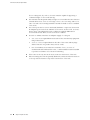
4
■
■
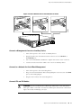
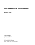
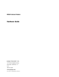
The rack rails must be spaced widely enough to accommodate the router chassis's
external dimensions: 3.5 in. (8.9 cm) high, 18.2 in. (45.7 cm) deep, and 17.5 in.
(44.5 cm) wide. The mounting hardware extends the width to fit into standard
19-in. racks.
■
For service personnel to remove and install hardware components, there must
be adequate space at the front and back of the router. At least 24 in. (61.0 cm)
both in front of and behind the rack or cabinet is required. NEBS GR-63
recommends at least 30 in. in front of the rack or cabinet.
■
The rack or cabinet must have an adequate supply of cooling air:
■
6 in. (15.2 cm) is required between the side of the router and any equipment
that produces heat.
■
2.8 in. (7.1 cm) is required between the side of the router and any large
surface that does not produce heat, such as a wall.
■
In a closed cabinet, there must be a minimum of 6 in. (15.2 cm) of
unobstructed airflow behind the router, or airflow baffles must be installed
to prevent recirculation of hot air and overheating.
■
If the router is the only unit in the rack, mount it at the bottom of the rack.
■
When mounting the router in a partially filled rack, load the rack from the bottom
to the top with the heaviest component at the bottom of the rack.
Step 1: Prepare the Site
Step 1: Prepare the Site
Figure 1: Rack Clearances and Router Dimensions
Tools Required
■
Phillips (+) screwdriver, numbers 1 and 2
■
Electrostatic discharge wrist strap
■
Antistatic mat
■
Blank panels to cover any slots not occupied by a component
Step 1: Prepare the Site
■
5
M7i Internet Router Quick Start
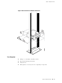
Step 2: Prepare for Front or Center Mounting
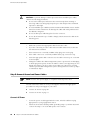
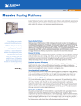
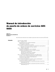
The cable management system organizes and supports the PIC cables to prevent
damage. The mounting brackets are shipped installed in the front-mounting position,
but must be removed to install the cable management system.
1.
Attach an electrostatic discharge (ESD) grounding strap to your bare wrist and
connect the strap to one of the ESD points on the chassis.
2.
Use a number 2 Phillips screwdriver to remove the screws from the front and
rear of the mounting brackets on the chassis. Remove the mounting brackets.
3.
Locate the cable management racks and appropriate screws in the accessory
box.
4.
Slide the cable management racks into the slots at the front of the chassis.
5.
Use a number 2 Phillips screwdriver to tighten the screws that secure the cable
management system to the chassis.
6.
Reinstall the mounting brackets.
■
Front-mount: Reinstall the mounting bracket in the position shown in
Figure 2 on page 6 and replace the screws.
■
Center-mount: Install the mounting brackets in the center-mounting position
and replace the screws.
Figure 2: Mounting Bracket in Front-Mounting Position
Figure 3: Cable Management System
6
■
Step 2: Prepare for Front or Center Mounting
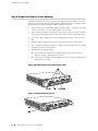
Step 3: Install the Router
Step 3: Install the Router
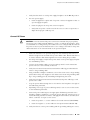
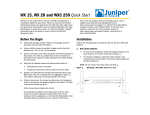
1.
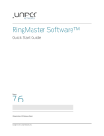
Have one person grasp each side of the router, lift the router, and position it in
the rack. See Figure 4 on page 8.
2.
Align the bottom hole in each mounting bracket with a hole in each rack rail,
making sure the chassis is level.
3.
Install a mounting screw (provided in the accessory box shipped with the router)
into each hole. Use a Phillips screwdriver to tighten the screws.
4.
Install a screw into the second hole in each mounting bracket.
5.
Verify that all the mounting screws on one side of the rack are aligned with the
mounting screws on the opposite side and that the router is level.
Step 3: Install the Router
■
7
M7i Internet Router Quick Start
Figure 4: Lift the Router into the Rack
Step 4: Connect External Devices and PIC Cables
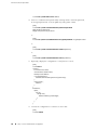
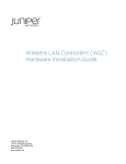
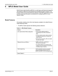
To connect external devices and PIC or FIC cables, perform the following procedures:
8
■
■
Connect a Management Console or Auxiliary Device on page 9
■
Connect to a Network for Out-of-Band Management on page 9
■
Connect FIC and PIC Cables on page 9
Step 4: Connect External Devices and PIC Cables
Step 4: Connect External Devices and PIC Cables
Figure 5: Connect External Devices and PIC Cables to Router
Connect a Management Console or Auxiliary Device
1.
Turn off the power to the console or auxiliary device.
2.
Plug the female end of the RS-232 serial connector into the CONSOLE or
AUX/MODEM port.
3.
Use a 2.5 mm flat-blade screwdriver to tighten the screws on the connector.
4.
Connect the other end of the cable to the console or auxiliary device.
Connect to a Network for Out-of-Band Management
1.
Turn off the power to the networking device.
2.
Plug one end of the Ethernet cable (with RJ-45/RJ-45 connectors) into the MGMT
port on the Routing Engine.
3.
Plug the other end into the networking device.
Connect FIC and PIC Cables
WARNING: Do not look directly into a fiber-optic transceiver or into the ends of
fiber-optic cables connected to a transceiver. Fiber-optic transceivers contain laser
light sources that can damage your eyes.
Step 4: Connect External Devices and PIC Cables
■
9
M7i Internet Router Quick Start
CAUTION: To prevent damage to fiber-optic transceivers and fiber-optic cables,
observe the following precautions:
■
Do not leave a fiber-optic transceiver uncovered except when inserting or
removing cable. The safety plug keeps the port clean and prevents accidental
exposure to laser light.
■
Do not bend fiber-optic cable beyond the maximum bend radius. An arc smaller
than a few inches in diameter can damage the cable and cause problems that
are difficult to diagnose.
■
Do not let fiber-optic cable hang free from the connector.
■
Do not allow fastened loops of cable to dangle, which stresses the cable at the
fastening point.
1.
Make sure you have the appropriate cable for the FIC or PIC.
2.
If you are connecting to a FIC or PIC with removable transceivers, make sure
the transceiver is installed.
3.
If the transceiver is covered by a rubber safety plug, remove the plug.
4.
If the cable connector is covered by a rubber safety cap, remove the cap.
5.
Insert the appropriate cable connector into the cable connector port on the FIC
or PIC faceplate.
6.
Arrange the cable in the cable management system to prevent it from dislodging
or developing stress points. Secure the cable so that it is not supporting its own
weight as it hangs to the floor. Place excess cable out of the way in a neatly
coiled loop in the cable management system. Placing fasteners on the loop helps
to maintain its shape.
Step 5: Connect Ground and Power Cables
NOTE: Connect each power supply to a separate external power source.
The M7i router uses either AC or DC power supplies. Perform the appropriate
procedure for each power supply in your router.
■
Connect AC Power on page 10
■
Connect DC Power on page 11
1.
Locate the power cords shipped with the router, which should have a plug
appropriate for your geographical location.
2.
Attach an electrostatic discharge (ESD) grounding strap to your bare wrist and
connect the strap to one of the ESD points on the chassis.
Connect AC Power
10
■
Step 5: Connect Ground and Power Cables
Step 5: Connect Ground and Power Cables
3.
Verify that the switch on each power supply faceplate is in the OFF (O) position.
4.
For each power supply:
a.
Insert the appliance coupler end of a power cord into the appliance inlet on
a power supply faceplate.
b.
Insert the plug into an AC power source receptacle.
c.
Verify that the power cord does not block access to router components or
drape where people could trip on it.
Connect DC Power
CAUTION: You must ensure that power connections maintain the proper polarity.
The power source cables might be labeled (+) and (–) to indicate their polarity. There
is no standard color coding for DC power cables. The color coding used by the external
DC power source at your site determines the color coding for the leads on the power
cables that attach to the terminal studs on the power faceplate.
1.
Make sure that there is no power flowing from the external power source, so
that the voltage across the leads of the power cables is 0 V. Ensure that there is
no chance that the cable leads might become active during the procedure.
2.
For each power supply, verify that the power switch on the power supply faceplate
is in the OFF (O) position.
3.
Connect the grounding cable to a proper earth ground for each external DC
power source, if it is not already connected.
4.
Verify that a licensed electrician has attached the cable lug provided with the
router to the grounding cable
5.
Using a number 2 Phillips screwdriver, remove the screw next to the grounding
symbol above the power supplies on the chassis rear. Secure the grounding cable
lug to the grounding point by reinstalling and tightening the screw.
6.
Verify that a licensed electrician has attached a listed power cable lug to each
power source cable.
7.
Loop the power cables through the hook located on the faceplate to the right of
the field-wiring terminals.
8.
Depending on the type of power cable lugs used, loosen or remove the screws
on the field-wiring terminals.
9.
Insert each power cable lug into the appropriate field-wiring terminal. Use a
number 1 Phillips screwdriver to secure the power cable lug. Turn the screw on
each field-wiring terminal clockwise, and apply between 8 lb-in. (0.9 Nm) and
9 lb-in. (1.02 Nm) of torque to each screw.
a.
Insert the positive (+) source cable into the return terminal (labeled RTN).
b.
Insert the negative (–) source cable into the input terminal (labeled –48).
10. Verify that the DC source power cabling and the grounding cabling are correct,
Step 5: Connect Ground and Power Cables
■
11
M7i Internet Router Quick Start
11. Verify that the power cables are not touching or blocking access to router
components, and that they do not drape where people could trip on them.
12. Switch on the external circuit breakers to provide voltage to the DC power source
cable leads.
Figure 6: Connect the Power Cables to a DC Router
Step 6: Power On the Router
12
■
1.
Verify that an external management device is connected to one of the Routing
Engine ports on the Routing Engine (AUX/MODEM, CONSOLE, or MGMT).
2.
Turn on the power to the external management device.
3.
Verify that the power supply is fully inserted in the chassis and the thumbscrews
on their faceplates are tightened.
4.
Verify that the power cord or cables are properly connected:
■
Verify that the ends of the AC power cord are firmly plugged into the
appliance inlet on the power supply faceplate and the external power source
receptacle.
■
Verify that the source DC power cables are connected to the appropriate
terminal on the power supply faceplate: the positive (+) source cable to the
return terminal (labeled RTN) and the negative (–) source cable to the input
terminal (labeled –48V).
5.
Press the power switch on the power supply faceplate to the ON (|) position.
6.
Monitor the startup procedure on the external management device to ensure
that the system boots properly.
Step 6: Power On the Router
Step 7: Perform Initial Software Configuration
7.
Verify that the OUPUT OK LED lights steadily. If the LED does not light after 60
seconds, repeat Steps 3 through 6. If necessary, reinstall the AC power cord or
DC power cables.
8.
For routers with two power supplies, repeat Steps 3 through 7 for the second
power supply.
Step 7: Perform Initial Software Configuration
This procedure connects the router to the network but does not enable it to forward
traffic. For complete information about enabling the router to forward traffic, including
examples, see the JUNOS Internet software configuration guides.
To configure the software, follow this procedure:
1.
Verify that the router is powered on as described in “Step 6: Power On the
Router” on page 12.
2.
Log in as the “root” user. There is no password.
3.
Start the CLI.
root# cli
root@>
4.
Enter configuration mode.
cli> configure
[edit]
root@#
5.
Configure the name of the router. If the name includes spaces, enclose the name
in quotation marks (“ ”).
[edit]
root@# set system host-name host-name
6.
Configure the router's domain name.
[edit]
root@# set system domain-name domain-name
7.
Configure the IP address and prefix length for the router's Ethernet interface.
[edit]
root@# set interfaces fxp0 unit 0 family inet address address/prefix-length
8.
Configure the IP address of a backup router, which is used only while the routing
protocol is not running.
[edit]
root@# set system backup-router address
9.
Configure the IP address of a DNS server.
[edit]
Step 7: Perform Initial Software Configuration
■
13
M7i Internet Router Quick Start
root@# set system name-server address
10. Set the root authentication password by entering either a clear-text password,
an encrypted password, or an ssh public key string (DSA or RSA).
[edit]
root@# set system root-authentication plain-text-password
New password: password
Retype new password: password
or
[edit]
root@# set system root-authentication encrypted-password encrypted-password
or
[edit]
root@# set system root-authentication ssh-dsa public-key
or
[edit]
root@# set system root-authentication ssh-rsa public-key
11. Optionally, display the configuration to verify that it is correct.
[edit]
root@# show
system {
host-name host-name;
domain-name domain-name;
backup-router address;
root-authentication {
authentication-method (password | public-key);
}
name-server {
address;
}
}
interfaces {
fxp0 {
unit 0 {
family inet {
address address/prefix-length;
}
}
}
}
12. Commit the configuration to activate it on the router.
[edit]
root@# commit
14
■
Step 7: Perform Initial Software Configuration
Safety Warnings
13. Optionally, configure additional properties by adding the necessary configuration
statements. Then commit the changes to activate them on the router.
[edit]
root@host# commit
14. When you have finished configuring the router, exit configuration mode.
[edit]
root@host# exit
root@host>
Safety Warnings
WARNING: See installation instructions before connecting the router. This is a
summary of safety warnings. For a complete list of warnings for this router, including
translations, see the M7i Internet Router Hardware Guide at
http://www.juniper.net/techpubs/.
WARNING: The intra-building port(s) of the router is suitable for connection to
intrabuilding or unexposed wiring or cabling only. The intra-building port(s) of the
router MUST NOT be metallically connected to interfaces that connect to the OSP or
its wiring. These interfaces are designed for use as intra-building interfaces only
(Type 2 or Type 4 ports as described in GR-1089-CORE, Issue 4) and require isolation
from the exposed OSP cabling. The addition of Primary Protectors is not sufficient
protection in order to connect these interfaces metallically to OSP wiring.
CAUTION: Before removing or installing components of a router, attach an ESD strap
to an ESD point and place the other end of the strap around your bare wrist. Failure
to use an ESD strap could result in damage to the router.
CAUTION: An external Surge Protective Device (SPD) should be used at the AC input
of the router.
■
Only trained and qualified personnel should install or replace the router.
■
Perform only the procedures described in this quick start or the M7i Internet
Router Hardware Guide. Other services should be performed by authorized service
personnel only.
■
Read the installation instructions before you connect the router to a power source.
■
Before installing the router, read the guidelines for site preparation in the M7i
Internet Router Hardware Guide to make sure that the site meets power,
environmental, and clearance requirements for the router.
Safety Warnings
■
15
M7i Internet Router Quick Start
■
When installing the router, do not use a ramp inclined at more than 10 degrees.
■
Manually installing the router requires two people to lift. To prevent injury, keep
your back straight and lift with your legs, not your back. Do not attempt to lift
the chassis by the power supply handles.
■
The router should be mounted at the bottom of the rack if it is the only unit in
the rack.
■
When mounting the router in a partially filled rack, load the rack from the bottom
to the top with the heaviest component at the bottom of the rack.
■
If the rack is provided with stabilizing devices, install the stabilizers before
mounting or servicing the router in the rack.
■
When removing or installing an electrical component, always place it
component-side up on a flat antistatic surface or in an electrostatic bag.
■
When you install the router, the ground connection must always be made first
and disconnected last.
■
Wire the DC power supply using the appropriate lugs. When connecting power,
the proper wiring sequence is ground to ground, +RTN to +RTN, then -48 V to
-48 V. When disconnecting power, the proper wiring sequence is -48 V to -48 V,
+RTN to +RTN, then ground to ground. The ground wire should always be
connected first and disconnected last.
■
Do not work on the system or connect or disconnect cables during electrical
storms.
■
Before working on equipment that is connected to power lines, remove jewelry,
including rings, necklaces, and watches. Metal objects heat up when connected
to power and ground and can cause serious burns or become welded to the
terminals.
■
Failure to observe these safety warnings can result in serious physical injury.
■
AC power cable warning (Japan):
WARNING: The attached power cable is only for this product. Do not use the cable
for another product.
16
■
Safety Warnings
Compliance Statements for NEBS
Compliance Statements for NEBS
This product complies with the following standards:
■
GR-63-Core: NEBS, Physical Protection
■
GR-1089-Core: EMC and Electrical Safety for Network Telecommunications
Equipment
■
SR-3580 NEBS Criteria Levels (Level 3 Compliance)
Compliance Statements for EMC Requirements
Canada
This Class A digital apparatus complies with Canadian ICES-003. Cet appareil
numérique de la classe A est conforme à la norme NMB-003 du Canada.
European Union
This is a Class A product. In a domestic environment this product may cause radio
interference in which case the user may be required to take adequate measures.
Compliance Statements for NEBS
■
17
M7i Internet Router Quick Start
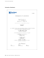
Declaration of Conformity
18
■
Compliance Statements for EMC Requirements
List of Technical Publications
List of Technical Publications
Table 1 on page 19 lists the software and hardware guides and release notes for
Juniper Networks J-series, M-series, MX-series, and T-series routing platforms and
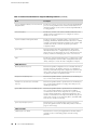
describes the contents of each document. Table 2 on page 22 lists the books included
in the Network Operations Guide series.
Table 1: Technical Documentation for Supported Routing Platforms
Book
Description
JUNOS Internet Software for Supported Routing Platforms
Class of Service
Provides an overview of the class-of-service (CoS) functions of the
JUNOS software and describes how to configure CoS features,
including configuring multiple forwarding classes for transmitting
packets, defining which packets are placed into each output queue,
scheduling the transmission service level for each queue, and
managing congestion through the random early detection (RED)
algorithm.
CLI User Guide
Describes how to use the JUNOS command-line interface (CLI) to
configure, monitor, and manage Juniper Networks routing
platforms. This material was formerly covered in the JUNOS System
Basics Configuration Guide.
Feature Guide
Provides a detailed explanation and configuration examples for
several of the most complex features in the JUNOS software.
High Availability Guide
Provides an overview of hardware and software resources that
ensure a high level of continuous routing platform operation and
describes how to configure high availability (HA) features such as
nonstop routing (NSR) and graceful Routing Engine switchover
(GRES).
MPLS Applications
Provides an overview of traffic engineering concepts and describes
how to configure traffic engineering protocols.
Multicast Protocols
Provides an overview of multicast concepts and describes how to
configure multicast routing protocols.
Network Interfaces
Provides an overview of the network interface functions of the
JUNOS software and describes how to configure the network
interfaces on the routing platform.
Network Management
Provides an overview of network management concepts and
describes how to configure various network management features,
such as SNMP and accounting options.
Policy Framework
Provides an overview of policy concepts and describes how to
configure routing policy, firewall filters, and forwarding options.
Routing Protocols
Provides an overview of routing concepts and describes how to
configure routing, routing instances, and unicast routing protocols.
List of Technical Publications
■
19
M7i Internet Router Quick Start
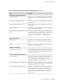
Table 1: Technical Documentation for Supported Routing Platforms (continued)
Book
Description
Secure Configuration Guide for Common Criteria
and JUNOS-FIPS
Provides an overview of secure Common Criteria and JUNOS-FIPS
protocols for the JUNOS Internet software and describes how to
install and configure secure Common Criteria and JUNOS-FIPS on
a routing platform.
Services Interfaces
Provides an overview of the services interfaces functions of the
JUNOS software and describes how to configure the services
interfaces on the router.
Software Installation and Upgrade Guide
Provides a description of JUNOS software components and
packaging, and includes detailed information about how to initially
configure, reinstall, and upgrade the JUNOS system software. This
material was formerly covered in the JUNOS System Basics
Configuration Guide.
System Basics
Describes Juniper Networks routing platforms, and provides
information about how to configure basic system parameters,
supported protocols and software processes, authentication, and
a variety of utilities for managing your router on the network.
VPNs
Provides an overview and describes how to configure Layer 2 and
Layer 3 virtual private networks (VPNs), virtual private LAN service
(VPLS), and Layer 2 circuits. Provides configuration examples.
JUNOS References
Hierarchy and RFC Reference
Describes the JUNOS configuration mode commands. Provides a
hierarchy reference that displays each level of a configuration
hierarchy, and includes all possible configuration statements that
can be used at that level. This material was formerly covered in
the JUNOS System Basics Configuration Guide.
Interfaces Command Reference
Describes the JUNOS software operational mode commands you
use to monitor and troubleshoot interfaces.
Routing Protocols and Policies Command
Reference
Describes the JUNOS software operational mode commands you
use to monitor and troubleshoot routing policies and protocols,
including firewall filters.
System Basics and Services Command Reference
Describes the JUNOS software operational mode commands you
use to monitor and troubleshoot system basics, including
commands for real-time monitoring and route (or path) tracing,
system software management, and chassis management. Also
describes commands for monitoring and troubleshooting services
such as class of service (CoS), IP Security (IPSec), stateful firewalls,
flow collection, and flow monitoring.
System Log Messages Reference
Describes how to access and interpret system log messages
generated by JUNOS software modules and provides a reference
page for each message.
J-Web User Guide
J-Web Interface User Guide
20
■
List of Technical Publications
Describes how to use the J-Web graphical user interface (GUI) to
configure, monitor, and manage Juniper Networks routing
platforms.
List of Technical Publications
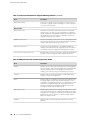
Table 1: Technical Documentation for Supported Routing Platforms (continued)
Book
Description
JUNOS API and Scripting Documentation
JUNOScript API Guide
Describes how to use the JUNOScript application programming
interface (API) to monitor and configure Juniper Networks routing
platforms.
JUNOS XML API Configuration Reference
Provides reference pages for the configuration tag elements in the
JUNOS XML API.
JUNOS XML API Operational Reference
Provides reference pages for the operational tag elements in the
JUNOS XML API.
NETCONF API Guide
Describes how to use the NETCONF API to monitor and configure
Juniper Networks routing platforms.
JUNOS Configuration and Diagnostic Automation
Guide
Describes how to use the commit script and self-diagnosis features
of the JUNOS software. This guide explains how to enforce custom
configuration rules defined in scripts, how to use commit script
macros to provide simplified aliases for frequently used
configuration statements, and how to configure diagnostic event
policies.
Hardware Documentation
Hardware Guide
Describes how to install, maintain, and troubleshoot routing
platforms and components. Each platform has its own hardware
guide.
PIC Guide
Describes the routing platform's Physical Interface Cards (PICs).
Each platform has its own PIC guide.
JUNOScope Documentation
JUNOScope Software User Guide
Describes the JUNOScope software graphical user interface (GUI),
how to install and administer the software, and how to use the
software to manage routing platform configuration files and monitor
routing platform operations.
J-series Routing Platform Documentation
Getting Started Guide
Provides an overview, basic instructions, and specifications for
J-series routing platforms. The guide explains how to prepare your
site for installation, unpack and install the router and its
components, install licenses, and establish basic connectivity. Use
the Getting Started Guide for your router model.
Basic LAN and WAN Access Configuration Guide
Explains how to configure the interfaces on J-series Services Routers
for basic IP routing with standard routing protocols, ISDN backup,
and digital subscriber line (DSL) connections.
Advanced WAN Access Configuration Guide
Explains how to configure J-series Services Routers in virtual private
networks (VPNs) and multicast networks, configure data link
switching (DLSw) services, and apply routing techniques such as
policies, stateless and stateful firewall filters, IP Security (IPSec)
tunnels, and class-of-service (CoS) classification for safer, more
efficient routing.
List of Technical Publications
■
21
M7i Internet Router Quick Start
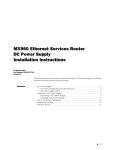
Table 1: Technical Documentation for Supported Routing Platforms (continued)
Book
Description
Administration Guide
Shows how to manage users and operations, monitor network
performance, upgrade software, and diagnose common problems
on J-series Services Routers.
Release Notes
JUNOS Release Notes
Summarize new features and known problems for a particular
software release, provide corrections and updates to published
JUNOS, JUNOScript, and NETCONF manuals, provide information
that might have been omitted from the manuals, and describe
upgrade and downgrade procedures.
Hardware Release Notes
Describe the available documentation for the routing platform and
summarize known problems with the hardware and accompanying
software. Each platform has its own release notes.
JUNOScope Release Notes
Contain corrections and updates to the published JUNOScope
manual, provide information that might have been omitted from
the manual, and describe upgrade and downgrade procedures.
J-series Services Router Release Notes
Briefly describe Services Router features, identify known hardware
problems, and provide upgrade and downgrade instructions
Table 2: JUNOS Internet Software Network Operations Guides
22
Book
Description
Baseline
Describes the most basic tasks for running a network using Juniper
Networks products. Tasks include upgrading and reinstalling JUNOS
software, gathering basic system management information,
verifying your network topology, and searching log messages.
Interfaces
Describes tasks for monitoring interfaces. Tasks include using
loopback testing and locating alarms.
MPLS
Describes tasks for configuring, monitoring, and troubleshooting
an example MPLS network. Tasks include verifying the correct
configuration of the MPLS and RSVP protocols, displaying the status
and statistics of MPLS running on all routing platforms in the
network, and using the layered MPLS troubleshooting model to
investigate problems with an MPLS network.
MPLS Log Reference
Describes MPLS status and error messages that appear in the output
of the show mpls lsp extensive command. The guide also describes
how and when to configure Constrained Shortest Path First (CSPF)
and RSVP trace options, and how to examine a CSPF or RSVP
failure in a sample network.
Hardware
Describes tasks for monitoring M-series and T-series routing
platforms.
■
List of Technical Publications
Requesting Support
Requesting Support
For technical support, open a support case with the Case Manager link at
http://www.juniper.net/support/ or call 1-888-314-JTAC (from the United States, Canada,
or Mexico) or 1-408-745-9500 (from elsewhere).
Revision History
30 April 2007—530-017640-01. Revision 2. Added NEBs requirements and other
safety warnings. Corrected DC connect procedure. Added list of technical publications.
12 January 2007—530-017640-01. Revision 1. Added EMC requirements and the
Declaration of Conformity. Minor edits.
28 June 2006—530-016682-01. Revision 1.
4 June 2004—530-010961-01. Revision 1.
Copyright © 2007, Juniper Networks, Inc. All rights reserved.
Juniper Networks, the Juniper Networks logo, NetScreen, and ScreenOS are registered trademarks of Juniper Networks, Inc. in the United States and other
countries. JUNOS and JUNOSe are trademarks of Juniper Networks, Inc. All other trademarks, service marks, registered trademarks, or registered service
marks are the property of their respective owners.
Juniper Networks assumes no responsibility for any inaccuracies in this document. Juniper Networks reserves the right to change, modify, transfer, or
otherwise revise this publication without notice.
Products made or sold by Juniper Networks or components thereof might be covered by one or more of the following patents that are owned by or licensed
to Juniper Networks: U.S. Patent Nos. 5,473,599, 5,905,725, 5,909,440, 6,192,051, 6,333,650, 6,359,479, 6,406,312, 6,429,706, 6,459,579, 6,493,347,
6,538,518, 6,538,899, 6,552,918, 6,567,902, 6,578,186, and 6,590,785.
Requesting Support
■
23