Download JAMO JSS4-TS User's Manual
Transcript
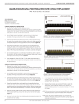
JSS4-TS WARNING: Improper installation could result in damage to the amplifier. Read all instructions before installation. Introduction Your JSS4-TS speaker selector allows simultaneous operation of up to 4 pairs of 8 Ohm speakers. Automatic load protection circuits assure that the amplifier will always see a load of 4 Ohms or higher no matter what combination of speaker is turned ON. The built-in protection circuit operates with switch pairs, permitting hookup choices for maximum power to your most frequently used speakers (up to 2 pairs). More information will be found under INSTALLATION below. The left and right channels are completely separate to assure safe operation with any type of amplifier, including those with isolated grounds (bridging outputs). Other features include power handling capability of up to 155 watts per channel. Installation When any speakers are turned on resistance is inserted in series with them in order to keep the amplifier load at 4 Ohms or higher. Coupling to any speaker is always direct when only one switch in ON The JSS4 rubber feet provide a non-marring, stable mount to permit convenient placement. Allow room for adequate ventilation around the switch box, it can become quite warm if operation at high power with the productive resistors switched in. Do not place on surfaces easily damaged by heat. The JSS4 front panel buttons all operate in the same manner, push to turn ON, push again to turn OFF. The switch is ON when pushed in closest to the JSS4 front panel. Caution: Do not apply audio power in excess of 155 watts per channel when the internal impedance matching resistors are switched in! DAMAGE TO COMPONENTS CAUSED BY EXCESSIVE POWER APPLICATION IS NOT COVERED UNDER WARRANTY. Connection To make a connection, strip about ¼in of insulation from the end, twist any loose strands together tightly so that no loose end sticks out to cause problems with short circuits. Make the connection by unscrewing the binding post counterclockwise and exposing the wire hole. Insert the stripped wire end into the wire hole and tighten the binding post by turning it clockwise. Make sure the metal conductor contacts the stripped part of the wire, not the insulation, and there are no loose strands to cause problem short circuits. Observe polarity when making connections, making sure +(plus) goes to + (plus), - (minus) goes to (minus) and that the channels are not crossed. Improper connections can cause the system to be inoperative or less than optimum. Following the same precautions, connect the speaker wires to the appropriate JSS4 terminals marked output. The scope of the warranty The warranty period will come into force as from the purchase date stated on the invoice. The warranty will apply for the following period of time: 2 years for electronics (power supply, amplifier, etc.) 7 years for other parts (cabinet, speaker units, etc.) In case of warranty inquiries, please contact your dealer. In case of request for service under warranty, please enclose your original receipt. Defects covered by the warranty: Except for the defects stated below, the warranty covers any production and material defects of the product. Defects not covered by the warranty: Defects arising from accidents, misuse, normal wear and tear, mis-maintenance, voltage variation, overloading, stroke of lightning, and other force majeure events Defects arising from incorrect installation or operation Defects arising from modification/repair/attempt of repair by a non-authorised service centre Defects arising from the use of non-original spare parts Defects on products with altered or lacking series number Other defects due to conditions or circumstances beyond the suppliers control Transportation costs for servicing are not covered by the warranty. The supplier is liable only to repair or replace defective parts or products. A replacement cannot exceed the value of the product under warranty. 69441 / 33.2000


