1
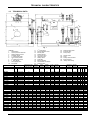
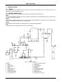
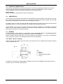
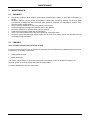
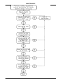
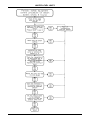
TECHNICAL MANUAL
AX
STEAM GENERATOR
INDEX
1 TECHNICAL CHARACTERISTICS ........................................................................................................... 2
1.1
GENERAL............................................................................................................................................... 2
1.2
CHARACTERISTICS.............................................................................................................................. 2
1.3
TECHNICAL DATA................................................................................................................................. 3
2 ACCESSORIES ......................................................................................................................................... 4
2.1
PRESSURE ............................................................................................................................................ 4
2.1.1
Pressure gauge............................................................................................................................ 4
2.1.2
Operation pressure switch ........................................................................................................... 5
2.1.3
Safety pressure switch................................................................................................................. 5
2.1.4
Safety valves................................................................................................................................ 6
2.2
LEVEL..................................................................................................................................................... 6
2.2.1
Level indicator gauge................................................................................................................... 6
2.2.2
Automatic level regulator and water level limits........................................................................... 7
2.3
FEED WATER ........................................................................................................................................ 7
3 INSTALLATION ......................................................................................................................................... 8
3.1
SITING .................................................................................................................................................... 8
3.2
WATER CONNECTIONS ....................................................................................................................... 8
3.3
ELECTRIC CONNECTIONS .................................................................................................................. 9
3.4
SMOKESTACK ....................................................................................................................................... 9
3.5
BURNER................................................................................................................................................. 9
3.5.1
Boiler - Burner coupling ............................................................................................................... 9
4 BOILER OPERATION ............................................................................................................................. 10
4.1
FIRST START-UP ................................................................................................................................ 10
4.2
NORMAL OPERATION ........................................................................................................................ 10
5 MAINTENANCE ....................................................................................................................................... 11
5.1
ORDINARY ........................................................................................................................................... 11
5.2
PERIODIC............................................................................................................................................. 11
5.2.1
Periodic control (every 6 hours of use)...................................................................................... 11
5.3
SCHEDULED........................................................................................................................................ 13
5.4
ConservaTION DURING WHEN OUT OF SERVICE........................................................................... 13
5.4.1
Dry conservation ........................................................................................................................ 13
5.4.2
Wet conservation ....................................................................................................................... 13
6 WATER CHARACTERISTICS................................................................................................................. 14
6.1
FEEDWATER - LIMIT VALUES (entering the boiler) ........................................................................... 14
6.2
OPERATING WATER - LIMITING VALUES ........................................................................................ 14
6.3
FREQUENCY OF THE ANALYSES..................................................................................................... 14
7
TROUBLESHOOTING............................................................................................................................. 15
8 WATER LEVEL LIMITS........................................................................................................................... 16
8.1
GENERAL............................................................................................................................................. 16
8.2
TYPICAL APPLICATIONS.................................................................................................................... 17
8.3
ELECTRICAL CONNECTIONS............................................................................................................ 17
8.4
STEAM GENERATOR OPERATION ................................................................................................... 18
8.5
FIRST START-UP ................................................................................................................................ 18
8.6
MAINTENANCE.................................................................................................................................... 18
8.6.1
Ordinary ..................................................................................................................................... 18
8.6.2
Periodic control (every 6 hours of use)...................................................................................... 18
8.6.3
Extraordinary maintenance (water level limits substitution) ...................................................... 20
8.7
TROUBLESHOOTING.......................................................................................................................... 20
8.8
DATA LABEL ........................................................................................................................................ 21
1
TECHNICAL CHARACTERISTICS
1
1.1
TECHNICAL CHARACTERISTICS
GENERAL
The AX series steam boilers are type semi-fixed, horizontal smoke-tube type, complete with accessories.
The boilers are suitable for operation with pressurised burners for gas, fuel oil or heavy oil.
Safety, reliability, high efficiency and high quality saturated steam are the characteristics of our boilers.
Please consult the instructions with attention.
This high-pressure steam (12-15 kgf/cm2) generator uses a combustion chamber with flue gas inversion. For
operation at up to 3000 kg/h of steam generated there is partial exoneration (in Italy) in the employment of
specialist boiler operators. Local requirements as to personnel qualification MUST be taken into account for
the country where the unit is installed.
1.2
CHARACTERISTICS
•
Working pressure switches for operation (controlling the 1st and 2nd burner flame).
•
Locking pressure switches (stops the burner on reaching the maximum steam pressure; the boiler is
manually reset from the control panel).
•
Automatic level regulator (2 probes connected to an electronic conductivity relay maintain the water
level between the set levels).
•
Water level limits (2 probes connected to two independent electronic conductivity relays stop the burner
if the water level falls below the safe minimum; reset is manual on the control panel).
2
TECHNICAL CHARACTERISTICS
1.3
TECHNICAL DATA
Fig. 1
LEGEND
1
Switchboard
2
Control pressure switches
3
Safety pressure switch
4
Pressure gauge
st
5
1 safety level probe
6
Level control probes
nd
7
2 safety level probe
st
8
1 level gauge
9
Level gauge drain
10 Front plate
Dimensions
AX
AX
AX
AX
AX
AX
AX
AX
AX
AX
AX
AX
AX
*
200
300
400
500
600
800
1000
1200
1500
1750
2000
2500
3000
Gasoil
Heavy oil
Total
weight
kg
Electric
supply
Volt ~
Steam intake
Feed
Safety valves exhaust
Boiler exhaust
Safety valves fitting
Lpg
Steam
capacity*
kg/h
N1
N2
N3
N4
N5
kcal/h
233
200.000
3,5
12
730
340
1500
3/N 400
50,0
IP55
4000
X
X
X
X
349
300.000
3,5
12
940
510
1800
3/N 400
50,0
IP55
4000
X
X
X
X
465
400.000
5,0
12
1090
680
2100
3/N 400
50,0
IP55
4000
X
X
X
X
581
500.000
4,5
12
1380
850
2600
3/N 400
50,0
IP55
4000
X
X
X
X
698
600.000
6,0
12
1585
1020
3000
3/N 400
50,0
IP55
4000
X
X
X
X
930
800.000
5,5
12
2030
1360
3600
3/N 400
50,0
IP55
4000
X
X
X
X
1163 1.000.000
7,0
12
2330
1700
4300
3/N 400
50,0
IP55
4000
X
X
X
X
1395 1.200.000
8,0
12
2860
2040
4700
3/N 400
50,0
IP55
10000
X
X
X
X
1744 1.500.000
6,5
12
3630
2560
6000
3/N 400
50,0
IP55
10000
X
X
X
X
2035 1.750.000
7,5
12
4020
3000
6500
3/N 400
50,0
IP55
10000
X
X
X
X
2326 2.000.000
8,0
12
4570
3410
7500
3/N 400
50,0
IP55
15000
X
X
X
X
2907 2.500.000
9,0
12
6220
4270
10000 3/N 400
50,0
IP55
15000
X
X
X
X
3488 3.000.000
9,5
12
6945
5100
11000 3/N 400
50,0
IP55
15000
X
X
X
X
H
Total
capacity
l
Rapid exhaust valve
Exhaust valve
Feed pumps
kW
Heat output
Design
Pressure
bar
22
23
24
Nat. gas
200
300
400
500
600
800
2000
1200
1500
1750
2000
2500
3000
nd
2 level gauge
Flame inspection hole
Burner plate
Steam take-off
Non return valve
Inspection door
Safety valves
Feed filter
Back smokebox
Smokestack connection
Cleaning door
Pressure losses
flue gas side
mbar
Characteristics
AX
AX
AX
AX
AX
AX
AX
AX
AX
AX
AX
AX
AX
11
12
13
14
15
16
17
18
19
20
21
Hz
Insulation
class
IP
Electric
power
W
Frequency
mm
1600
H1
mm
1240
H2
mm
575
H4
mm
1440
H6
mm
720
L2
L4
L
P
mm
mm
mm
mm
1480 1080 1130 2060
P2
P6
Øb
Øc
mm
mm
mm mm
1508 280-330 180 250
1780
1400
640
1600
815
1640 1240 1290 2092
1511 310-360 225 250
32
1”1/4
1800
1400
640
1620
815
1640 1240 1290 2342
1761 310-360 225 250
40
1”1/4
1980
1560
700
1780
900
1800 1400 1450 2381
1760 350-400 280 300
40
2010
1560
700
1780
900
1800 1400 1450 2631
2010 350-400 280 300
2160
1710
735
1930
950
1950 1550 1600 2661
2220
1710
735
1940
950
2370
1850
2550
Fuel
N4
DN/in
32
N5
DN/in
25
40
32
25
40
32
25
1”1/4
40
32
25
50
1”1/4
40
32
25
2010 370-420 280 350
50
1”1/4
40
32
25
1950 1550 1600 2961
2310 370-420 280 350
65
1”1/4
40
32
25
810
2080 1000 2100 1680 1730 3163
2512 370-420 320 400
65
1”1/4
40
32
25
1990
850
2240 1080 2260 1840 1890 3413
2710 420-470 360 450
80
1”1/4
40
32
25
2550
1990
850
2240 1080 2260 1840 1890 3713
3010 420-470 360 450
80
1”1/4
50
32
32
2710
2150
880
2390 1240 2450 1950 2000 3785
3013 480-530 360 500
80
1”1/4
50
32
32
2900
2300
950
2550 1240 2600 2100 2150 4283
3504 480-530 400 550
100
40
50
40
32
3000
2400
970
2615 1300 2700 2200 2250 4626
3754 480-530 400 600
100
40
65
40
40
80°C feeding water
3
N1
N2
N3
DN/in DN/in DN/in
32
1”1/4 40
ACCESSORIES
2
ACCESSORIES
AX steam boilers are fitted with a series of accessories that can be subdivided as follows:
• Safety accessories (safety valves, water level limits, safety pressure switches).
• Observation accessories (level gauge, pressure gauge, flame inspection).
• Control accessories (level ad pressure switches).
• Feed water accessories (centrifugal pump, injector or alternating steam pump).
• Manual operation accessories (stop valves, purge valve).
In the following description the accessories are subdivided as to the physical parameter they control
(pressure and level).
2.1
PRESSURE
2.1.1 Pressure gauge (Fig. 2)
The pressure gauge is Bourdon type consisting of a flat elliptical
section metal tube, bent to an arc. One end of the tube is open
and communicates with the boiler where the pressure is to be
measured; the other end, closed and free to move is connected by
a lever system to a toothed arc and to the gauge indicator hand.
The gauge shows in red the design pressure.
The gauge is carried on a three-way valve to allow the following
operations:
• Communication between boiler and gauge (normal operation
position).
• Communication between gauge and the atmosphere (position
necessary to purge the siphon).
• Communication between the boiler, the gauge and a test
gauge (position necessary to verify the gauge).
Fig. 2
4
ACCESSORIES
2.1.2 Operation pressure switch
Device that controls the boiler pressure and holds the pressure between the set maximum and minimum
values.
Instructions for adjustment.
The electric switch has three screws (2-1-3 from right to left).
On reaching the set pressure, the contact 2-1 switches to 2-3.
Adjustment of the pressure switch (Fig. 3):
a) Turn the knob (1) until the scale indicator (2) reaches the pressure at which the burner shall restart.
b) Remove the cover of the pressure switch and position the drum (3) at the value selected for the pressure
differential (stopping the burner) as to the diagram Fig. 4.
Example:
* Type of pressure switch: RT 5
* Scale indicator 9 bar
* Drum indicator: 4 corresponding to 2,1 bar
* Burner start:
9 bar
* Burner stop:
11,1 bar
Fig. 3
Fig. 4
2.1.3 Safety pressure switch
This switch is set at a higher pressure than the maximum of the control pressure switch, but always lower
than the opening pressure of the safety valves.
The safety pressure switch acts in the case of a fault to the control pressure switch and stops the burner
permanently. Restarting the burner can only occur after the steam pressure has fallen and after a manual
reset on the switchboard.
This pressure switch is adjusted in a similar manner to that of the control pressure switch, with the only
precaution that the drum indicator is set to 1 so that the differential is effectively nil.
5
ACCESSORIES
2.1.4 Safety valves
These valves have the function of discharging steam
when the maximum design pressure of the boiler is
reached.
The valves used on boilers can be of the type Lever and
weight (Fig. 5) or Spring (Fig. 6).
The boiler operator must pay much attention to the safety
valves and carry out careful and diligent maintenance.
The safety valve is the most important and sensitive
accessory on the boiler and represents the best
guarantee that the internal pressure of the boiler does not
exceed the design pressure.
As during normal operation of a boiler, the safety valve
never acts, it is good practice to check that the valve is
free, i.e. that the valve plug is not stuck to the seat, by
acting on the side lever (spring valves) or on the
horizontal lever carrying the weight (lever and weight
valves) until the valve starts to discharge steam.
WARNING
On first start-up, you must verify that safety valve
Fig. 5
adjustment is made to the boiler design pressure.
Generally the spring safety valve is supplied already adjusted, while the lever
and weight type must be adjusted by moving the weight along the lever until the
opening pressure value corresponds to the boiler design pressure.
The safety valve installed on steam boilers must have the discharge piped to
outside the boiler room. Particular care must be taken in designing the
discharge line; we show some here.
• The discharge line should e of diameter at least equal to that of the
discharge flange on the safety valve.
• Only wide radius curves must be used in the discharge line.
• The entire discharge line must be built to avoid the formation of
condensation locks. There must be therefore adequate slopes to ensure
complete drainage.
Particular care must be taken if the valve seat and plug are to be ground; if this
operation becomes necessary due to leaks, use abrasives based on silicon
carbide or oil based carborundum. Carry out the first grinding operation using
fine grain abrasive, finishing with a very fine grain abrasive.
2.2
LEVEL
Fig. 6
2.2.1 Level indicator gauge
The level indicator consists of a pair of valves connected to a sight glass box containing a prismatic glass.
This device is connected to the boiler both above and below the normal water level, while the lower part is
fitted with a purge valve so that any sludge can be removed, to keep the glass clean. Using these valves, the
efficiency of the level control system can be verified periodically by carrying out the following operations:
• Open for a few seconds and then close the purge valve. If the water disappears from the sight glass and
then appears again with ample level oscillation, then it can be considered that the level operates correctly.
If on the other hand the water returns slowly or stops at a level differing form the preceding level, then on of
the communications may be obstructed. To make sure which of the two is obstructed, and to attempt a
purge, close the steam valve leaving the water valve open, then open the purge valve. This valve must
release water taking with it any sludge formed in the pipes. Then close the water valve and open the steam
valve: steam should be released from the purge valve. Closing the purge valve and leaving the two water
and steam valves open, the water should return to the initial level. If this does not occur, the
communication pipes between the level and the boiler must be cleaned.
6
ACCESSORIES
2.2.2 Automatic level regulator and water level limits (Fig. 7)
The physical principle employed to detect and control the water level is based on the electrical conductivity
of the water. The control device consists of a part sited in the control panel (electronic relays) and of probes
of differing lengths immersed in the boiler shell.
Operation of the system provides for:
• Automatic pump start and stop: Two probes inserted in the boiler, of which the longer starts, and the
shorter stops the pump, connected to a single control relay in the control panel.
• Burner stop at low water level: two probes of the same length, inserted in the boiler and connected to
two distinct control relays in the control panel, stop the burner permanently if the water level drops below
the admissible level.
Boiler probes:
6
7
8
9
Pump stop
Pump start
1st safety burner stop and alarm on.
2nd safety burner stop and alarm on.
N.B.: we suggest that as well as the
acoustic alarm in the boiler room, a
further acoustic alarm be provided in
an area where personnel is normally
present.
Fig. 7
2.3
FEED WATER
An electric centrifugal pump supplies the water. The inlet side of the pump must never be under suction
pressure, but always under positive pressure due to the difference in height between the pump itself and the
feed water tank. While a pump can operate under suction head from a cold water tank (up to 5-6 m), if the
water is hot the pump cannot operate and indeed needs the water to be delivered under a certain pressure.
The height of the feed water tank varies with the temperature, as shown in the following table:
Feed water temperature
(Celsius)
60
70
80
90
Positive water head
(metres)
1
2
3
4,5
WARNING
• Avoid the use of feed water at temperatures lower than 60 Celsius, being rich in Oxygen and
therefore such as to cause corrosion.
• To avoid pump cavitation problems, the feed water temperature should not be higher than 90
Celsius.
7
INSTALLATION
3
3.1
INSTALLATION
SITING
Our steam boilers are supplied as units and do not need any foundation work. A flat even floor only is
needed, that can be raised by 5-10 cm.
3.2
WATER CONNECTIONS
The steam boilers once positioned are connected to the system as follows (Fig. 9):
Water
From the condensate collection tank (10) (if existing; otherwise from the treated water tank) to the suction
side of the feed water pump (9).
Steam
From the main steam take-off valve (3) to the user services (distributor or others), from the safety valve
outlets (6) to outside the boiler room in a safe position.
Drains
From the level indicator drains (16), the boiler drain (17) to the drainage network.
Fuel
Connection to the burner foreseen for fuel oil or natural gas.
Fig. 9 – System diagram
10.
11.
12.
13.
14.
15.
16.
17.
18.
19.
LEGEND
1. Boiler
2. Smokestack
3. Steam take-off
4. Burner
5. Pressure switches
6. Safety valves
7. Condensate return
8. Electric pump supply
9. Feed water pumps
8
Condensate collection tank
Water level
Water treatment
Water supply
Breather
Condensate tank drain
Level indicator drain
Boiler drain
Safety valve drain
Example of user service
INSTALLATION
3.3
ELECTRIC CONNECTIONS
The boilers are provided with a switchboard (protection level IP 55) completely assembled to the various
boiler accessories. Before connecting the switchboard, make sure that the electric system has been
correctly installed, checking in particular the efficiency of the earthing system.
Wiring diagram
Refer to the diagram supplied with the specific switchboard.
3.4
SMOKESTACK
The connection from the boiler to the base of the smokestack must slope upwards in the direction of the gas
flow, with a slope that should be at least 10%. The path should be as short and as possible and the bends
and connections designed as to the rules used in the design of air ducts.
For lengths of up to 2 metres, the same diameter as the boiler flue gas outlet can be used (see the technical
specification table). For more tortuous paths, the diameter must be suitable increased.
The smokestack must in any case be dimensioned as to applicable regulations. It is advisable to pay great
attention to the inside diameter, insulation, gas tightness, ease of cleaning and to the fitting required for
taking flue gas samples for combustion analysis.
3.5
BURNER
To better answer to steam demand, it is advisable to install a two-stage burner or a modulating burner;
this avoids large pressure variations consequent on sudden stream demands.
Further, and above all with natural gas, every burner start-up is preceded by a long period of preventilation
of the combustion chamber, with consequent loss of heat to the smokestack.
3.5.1 Boiler - Burner coupling
Verify that the spaces between the burner sleeve and the boiler door are suitable filled with flame-resistant
ceramic insulation (Fig. 10).
P6
Fig. 10
Øb
KEY:
1. Burner
2. Manhole
3. Thermoinsulating material
4. Flange
1
3
4
2
All details on the draught tube lenght (P6), the diameter of the burner hole (Øb) and the pressurization are
included in the par. Technical Specifications.
9
BOILER OPERATION
4
4.1
BOILER OPERATION
FIRST START-UP
WARNING: Before start up insert all the turbolators into the smoke tubes ensuring that there is a
space of at least 100 mm at the front after they have been pushed fully inside.
• Verify that all fittings are tight.
• Verify that the feed water pipes are clean, carrying out a series of washing operations with drainage to
waste before final boiler filling.
• Close the drain valves, the steam take-off valve and the level drains.
• Open the level control valves and the feed water valve (upstream of the feed water pump).
• Check that the upper man-way is correctly closed.
• Start the boiler as follows:
1)
Switch on the control panel by turning the main switch.
2)
Check that the drive shaft of the feed water pump is free to turn. By starting the pump manually for an
instant, check that the shaft turns in the correct direction.
3)
Set the pump switch to AUT and verify that burner cannot start before the attainment of the minimum
level;
4)
Check that the pump stops when the maximum level is reached by observing the level indicators and
checking the positions of the indicator valves.
5)
Press and keep pressed the safety water level reset button for at least 10 seconds, the conductivity
relay being of the delayed type.
6)
Open the boiler drain and check on the level indicator at what level the pump-start probe acts.
7)
Set the pump switch to “0” leaving the drain open and check the actuation level of the safety probes
with respect to the minimum level reference plate.
8)
Close the drain and set the pump switch to AUT
9)
Switch on the burner and bring the boiler up to pressure adjusting the operation pressure.
WARNING: On boilers with a man-way, during the first start-up it is important to tighten progressively the
nuts on the man-way cover as the pressure increase. Otherwise a hazardous situation is created due to
steam leaks that quickly deteriorate the gasket creating a dangerous situation for the boiler room personnel.
4.2
NORMAL OPERATION
With cold start-ups, verify that:
•
•
•
•
The boiler is full of water to the minimum level;
The increase of the water volume due to heating does not raise the water level too far: if necessary drain
the boiler at regular intervals to bring the visible level back to the centre of the water level sight glasses;
On reaching the set pressure, the steam take-off valve can be opened very gradually in order to heat the
steam delivery lines eliminating any condensate that may be present in the pipework;
The man-way gasket does not leak.
10
MAINTENANCE
5
5.1
•
•
•
•
•
•
•
•
5.2
MAINTENANCE
ORDINARY
Periodically purge the level gauges, probe holder if fitted and the boiler, to avoid the accumulation of
sludge;
Check the efficiency of the control and regulation instruments, examining carefully the electrical parts
(connections included) and the mechanical parts (pressure switches); it is advisable to replace every
year the ceramic probe-holders;
Carry out burner maintenance (as to the specific instructions);
Check the tightness of flange bolts and the state of the gaskets;
Check the conditions of the boiler door internal covering;
Clean the flue-gas tube bundle and the turbolators;
Carry out correct maintenance to the pump (bearings, mechanical seal),
Check for wear to the discharge valves; these tend to wear more quickly, due to the abrasive effect of
the sludge during blow-down.
PERIODIC
5.2.1 Periodic control (every 6 hours of use)
From time to time (every 6 hours of use) the thermal plant must be inspected by qualified personnel to check
the efficiency of all safety accessories:
•
Safety pressure switch
•
Water level limits
The system can be reset if no anomalies have been encountered: power off the panel for approx. 20
seconds, power on the main switch and press the reset buttons.
For further details follow the flow chart below:
11
MAINTENANCE
12
MAINTENANCE
5.3
SCHEDULED
All boilers must be periodically stopped for careful inspection and maintenance: the time interval between
stops is established by experience, by the operating conditions, by the quality of the feed water and by the
type of fuel used.
Before entering the boiler shell for inspection or for cleaning, check carefully that there is no possibility of
entry of water or steam via the pipework to which the boiler is connected. Every valve must be locked and if
necessary isolated by removing a piece of pipework or by inserting a blind flange.
The parts under pressure must be carefully examined internally to identify any encrustation, corrosion and
other potential sources of danger linked to the feed water.
All deposits must be removed mechanically or chemically and the effective thickness of the structures
must be verified using suitable instruments to determine that they are equal to or greater than the
design values. All pustules or other types of corrosion must be scraped and cleaned with a steel wire brush
to white metal. Leaks between fire tubes and tube plates must be carefully examined: any welding must be
done in all cases observing legal obligations, without forgetting that a steam boiler is a pressure vessel with
danger of explosion and subject to control by competent authorities.
During inspection also verify all the accessories, with priority to safety valves, level probes and pressure
switches.
5.4
CONSERVATION DURING WHEN OUT OF SERVICE
Often during periods of disuse the worst cases of corrosion appear. The operations to be carried out to
guarantee correct conservation of the boiler depend essentially on the duration of the stop.
The boiler can be subjected to dry conservation if the period of disuse is long, or to a wet conservation for
short stops or if the boiler has a back-up function and must be ready to come on-line in a short time.
In both cases, the necessary operations tend to eliminate the causes of possible corrosion.
5.4.1 Dry conservation
The boiler must be drained and dried carefully, then placing in the boiler shell a hygroscopic substance (for
example lime or silica gel etc)
5.4.2 Wet conservation
The boiler must be filled completely, given that corrosion is a phenomenon that appears due to the
simultaneous presence of water and Oxygen. Therefore all traces of Oxygen must be removed from the
water, also avoiding the successive infiltration of air. There are substances that absorb Oxygen, such as
hydrazine and Sodium Sulphite, but after their use the water alkalinity must be checked.
13
WATER CHARACTERISTICS
6
WATER CHARACTERISTICS
For steam generators with heating surface over 15 sqm, there are some regulations that require limit
values for water characteristics. These values are listed in the tables below.
However, limits should be adopted for all generators as stated by qualified companies that recommend the
type of treatment to be carried out basing on careful analysis of the available water. Many faults and
sometimes serious accidents are caused by the use of water with non-conforming features.
6.1
FEEDWATER - LIMIT VALUES (entering the boiler)
Tab.1
Characteristics
pH
Total hardness
Oxygen (1)
Free Carbon Dioxide (1)
Iron
Copper
Oily substances
Aspect
Unit of measurement
mg/l CaCo3
mg/l O2
mg/I CO2
mg/l Fe
mg/l Cu
mg/I
Pressure ≤ 15 bar
Pressure ≤ 25 bar
7 $ 9,5
7 $ 9,5
10
5
0,1
0,05
0,2
0.2
0,1
0,1
0,1
0.1
1
1
Clear, limpid, no persistent foam.
(1) These values are valid to have a thermo degassing device. Without degassing device, the temperature of the tank
water must be increased to at least 80 Celsius (see chapter 2.3. - Feeding) to reduce the content of dissolved
gasses (O2 and CO2). Chemical deoxygenators must be used to remove completely the oxygen from the feed water
and reduce as much as possible CO2 corrosive effects.
6.2
OPERATING WATER - LIMITING VALUES
Tab.2
Characteristics
pH
Total alkalinity
Total hardness
Maximum conductivity (4)
Silica
STD (4)
Conditioner (2)
Aspect
Unit of measurement
Pressure ≤ 15 bar
9 $ 11
1000
10
8000
150
3500
mg/l CaCo3
mg/l CaCo3
µS/cm
mg/l SiO2
mg/l
Pressure ≤ 25 bar
9 $ 11
750
5
7000
100
3000
Clear, limpid, no persistent foam
(1) To maintain in the boiler the parameters of alkalinity and silica within the prescribed or recommended limits, the boiler
must be purged, if possible continuously. The values of the concentrations in the feedwater and in the boiler water are
linked to the continuous purge by the following relationship:
S % = 100
Ca
Cc
Where
S%
Ca
Cc
= Percentage of purge with respect to the feed water supplied to the boiler;
= Real concentration of a certain salt or ion in the feed water
= Maximum allowed concentration in the boiler for the same salt.
(2) Correct management presupposes normally the use of conditioners, whose dosages and limits are in relation to the
nature and characteristics of the additives themselves.
(3) Determined on a filtered sample
(4) The two parameters have the same physical meaning but the values can be correlated only if the chemical
composition of the water is known.
6.3
FREQUENCY OF THE ANALYSES
The frequency of analysis is determined evidently as a function of the use of the boiler and of the quality of
the water used; it is advisable in any case to check the pH, the total hardness and the alkalinity of the feed
and boiler waters at least every two days. Once a month, especially under conditions of variable operation, it
is advisable to subject meaningful samples of the boiler and feed waters to complete analysis.
It is also advisable to inspect the return condensate for traces of any highly contaminating oily substances
(reduction of evaporation from the water surface in the boiler caused by a layer of oil).
14
TROUBLESHOOTING
7
TROUBLESHOOTING
FAULT
Safety valve/s opening
PROBABLE CAUSE
Maximum pressure exceeded, as set on
the valve. Must be equal to the boiler
design pressure.
Loss of the adjustment of the safety valve
SUGGESTED REMEDY
Adjust the safety pressure switches
and / or limit switches.
Check and then adjust the valve using
a reference gauge
Clean the seat by opening the valve
Small leaks from the safety Dirt on the valve seat
manually a few times
valve/s
Marks on the valve seat
Dismantle the valve and regrind the
valve seat with very fine abrasive.
Pump overload relay has acted
Check the motor current
Pump stopped
Check the relay setting
Pump shaft seized
Maintenance to the pump
Pressure limit switch set too high
Adjust the pressure limit switch
Pressure safety switch operates
Pressure limit switch faulty
Replace the pressure limit switch
Pressure switch pipe coil blocked
Clean or replace the pipe coil
Water level detection interrupted
Steel probe encrusted
Safety level 1 or 2 operates
Connection cable interrupted
Safety level relay faulty
Temporary replacement of the safety
electronic relay with one of the two
relays in the panel.
If the problem disappears, replace the
faulty relay.
No water feed
See faults "feed water"
Pump seized
See faults "Pump stopped"
Feed water insufficient
Pump suction filter blocked
Clean the filter
Level control faulty
Temporary
replacement
of
the
electronic control relay with one of
those present in the panel.
If the problem disappears, replace the
faulty relay.
Level probes short circuited
Dismantle the control probes for
inspection of the ceramic insulation
Pump cavitation
Suction head (difference in height
between supply tank and pump)
insufficient in relation to the water
temperature
Clean the pump suction filter
Reduce the head loss in the pipe
between collector tank and the pump
by increasing the pipe section
Pump rotation direction
Invert two phases (three-phase pump)
Erroneous electrical connection to the Consult the wiring diagram
Burner always ON
panel
Safety level relays faulty
See “Intervention safety level 1 or 2”
Control and/or safety pressure switches Check the adjustment of the pressure
switches
inactive
Check the pressure switch connections
to the control panel
Problems with the burner
See the specific burner Manual
Burner always OFF
Burner fuses interrupted
Replace the fuses
No consent to the burner from the control Replace the control pressure switch
pressure switch
No consent to the burner from the safety See “Intervention safety level 1 or 2”
level relay
Erroneous connection to the control panel Consult the wiring diagram
15
WATER LEVEL LIMITS
8
8.1
WATER LEVEL LIMITS
GENERAL
The water level limits consists in: n. 2 level rods, n. 2 probes, electrical cables, n. 2 electronic relays. The
device prevents the lowering of the level of water in the steam generators and the consequent overheating of
the membrature.
The principle of survey and control of the level is based on water conductivity. In order to guarantee
the correct operation of the device, following conditions must be fulfilled:
•
•
•
Water conductivity >
Water temperature <
Pressure
<
250 µS/cm
210°C
20 bar
(See. " Operating water " - Tab. 2 ).
EXAMPLE: PROBES TANK FOR SAFETY AND REGULATION
16
WATER LEVEL LIMITS
8.2
TYPICAL APPLICATIONS
Boiler probes:
6 Pump stop
7 Pump starting
8 1st burner cut-out safety device and alarm ON.
9 2nd burner cut-out safety device and alarm ON
NOTE: it is recommended that an alarm bell is installed in the
boiler room as well as a sound or visual alarm in highly visited
rooms.
8.3
ELECTRICAL CONNECTIONS
Refer to the diagram supplied with the specific
switchboard.
17
WATER LEVEL LIMITS
8.4
STEAM GENERATOR OPERATION
(Water level limits)
8.5
•
FIRST START-UP
Start the boiler, as follows:
1
Power up the boiler control panel
2
Make sure that the motor-driven pump drive shaft is free to rotate and that rotation direction is correct.
3
Set the pump selector switch on AUT and verify that burner cannot start before the attainment of the
minimum level;
4
Make sure that the pump stops when the maximum level is reached, observing level indicators and
checking the position of their cocks;
5
Maintain safety level reset pressed for 10 sec because it is employed an electronic delayed relay
6
Open the boiler discharge and check on the level indicator the intervention point of probe pump start
7
Set the pump selector switch on "0", leaving the discharge open, and check the intervention level of
safety probes, referring to the minimum level information plate;
8
Close the discharge, place pump selector switch to AUT;
8.6
MAINTENANCE
8.6.1
Ordinary
• Bleed periodically (level indicators, probe-holder barrel if any, boiler) to avoid mud deposits.
• Check the efficiency of the regulation and control instruments by inspecting carefully the electrical (also
connections); it is also recommended that the probe-holder ceramic plugs are replaced every year
8.6.2
Periodic control (every 6 hours of use)
From time to time (every 6 hours of use) the thermal plant must be inspected by qualified personnel to check the efficiency
of all safety accessories:
•
Water level limits
•
Safety valve
The system can be reset if no anomalies have been encountered: power off the panel for approx. 20 seconds, power on
the main switch and press the reset buttons.
For further details follow the flow chart below:
18
WATER LEVEL LIMITS
19
WATER LEVEL LIMITS
8.6.3
Extraordinary maintenance (water level limits substitution)
To replace the water level limits or parts of it, follow strictly the instructions below:
1. Ensure that the new ceramic plug is intact
2. Check the length of the rod
3. Ensure that the rod is coaxial to the plug axis
4. Inspect the electrical system and, in particular, ensure that the resistance of the electric circuit linking
the ceramic plug to the electrical panel is intact (resistance must be over 10 MOhm)
5. Ensure that the automatic level control consisting of the two ceramic plugs and their conductivity-relays,
work well
8.7
TROUBLESHOOTING
FAULT
Safety intervention level 1 or 2
Insufficient water load
Burner always on
Burner always off
POSSIBLE CAUSE
Interrupted water level monitoring
RECOMMENDED REMEDY
Scaled stainless steel bar
Broken connection cable
Faulty safety level relay
Temporary replace the safety electronic
relay with one of the two relays in the
panel.
If this is the problem, replace definitively
the faulty relay.
Water does not load
See “Loading” inconv.
Blocked pump
See. “Blocked pump” inconv.
Dirty pump sucking filter
Clean the filter
Level regulation anomaly
Temporary replace the safety electronic
relay with one of the two relays in the
panel.
If this is the problem, replace definitively
the faulty relay.
Level regulation probes short circuit
Dismantle the adjustment probes to
inspect visually the ceramic insulation
Pump cavitatation
Insufficient head (=different height
between the collecting vessel and the
pump levels) in comparison with water
temperature
Clean the pump sucking filter
Decrease the pipe resistance between the
collecting vessel and the pump by
increasing the passage section
Pump sense of rotation
Invert one of the two phases (three-phase
pump)
Incorrect electrical panel connection
Consult the electric diagram
Faulty level safety relays
See “Safety intervention level 1 or 2”
Regulation pressure and/or safety switches Check the pressure switches regulation
OFF
Check the pressure switches connection
to the electrical panel
Burner problems
See burner manual
Interrupted burner fuses
Replace fuses
Lack of burner consent from the regulation Replace regulation pressure switch
pressure switch
Lack of burner consent from the level safety See “Safety intervention level 1 or 2”
relays
Incorrect electrical panel connection
Consult the electric diagram
20
WATER LEVEL LIMITS
8.8
DATA LABEL
ICI CALDAIE S.p.A.
Via G. Pascoli, 38 - S.S. 434 km 9
37059 ZEVIO/Fraz. Campagnola
VERONA - ITALIA
Tel. 045/8738511 -fax 045/8731148
LIVELLOSTATO DI SICUREZZA
WATER LEVEL LIMITS
Modello / Model
GP1
Boiler serial number
N.fabb. / Serial number
Conducibilità dell’acqua
Water conductivity
> 250 µS/cm
PS max
TS max
Fluido / Fluid
Data/Date
Volt / Freq. / Pot. - Power
20 bar
210°C
Acqua / Water
24 VAC / 50-60 Hz / 3 VA
Omologazione/Approval
1370
IL LIVELLOSTATO DI SICUREZZA
DEVE ESSERE VERIFICATO OGNI
6 ORE DI FUNZIONAMENTO
WATER LEVEL LIMIT SHALL BE TESTED
PERIODICALLY FOR A MAX OF 6 HOURS
(ved. MANUALE TECNICO/see TECHNICAL MANUAL)
21
Boiler final test date
Appartenente al Gruppo Finluc, iscritto R.I. VR n. 02245640236
Via G. Pascoli, 38 - 37059 Zevio - fraz. Campagnola - VERONA - ITALIA
Tel. 045/8738511 - Fax 045/8731148
[email protected] - www.icicaldaie.com
The data reported are indicative only and are not binding. Our company reserves the right to introduce alterations at any time, as it
deems fit and proper for the development of the product.
96020005 Ed. 13-05/09
13 - St. 10 – 05/09