1
FT900
Owner's Manual
"This machine is approved by the EPA for E10 (10% ethanol) and lower fuel only.
Do not use any fuel >E10 in this machine."
532 43 99-99
SAFETY RULES
Safe Operation Practices for Walk-Behind Powered Rotary Tillers
TRAINING
•
•
•
•
Read the Owner’s Manual carefully. Be thoroughly
familiar with the controls and the proper use of the
equipment. Know how to stop the unit and disengage
the controls quickly.
Never allow children to operate the equipment. Never
allow adults to operate the equipment without proper
instruction.
Keep the area of operation clear of all persons, particularly small children, and pets.
•
•
•
•
•
•
PREPARATION
•
•
•
•
•
•
•
•
•
•
Thoroughly inspect the area where the equipment is
to be used and remove all foreign objects.
Disengage all clutches and shift into neutral before
starting the engine (motor).
Do not operate the equipment without wearing adequate outer garments. Wear footwear that will improve
footing on slippery surfaces.
Handle fuel with care; it is highly flammable.
Use an approved fuel container.
Never add fuel to a running engine or hot engine.
Fill fuel tank outdoors with extreme care. Never fill fuel
tank indoors.
Replace gasoline cap securely and clean up spilled
fuel before restarting.
Use extension cords and receptacles as specified by
the manufacturer for all units with electric drive motors
or electric starting motors.
Never attempt to make any adjustments while the
engine (motor) is running (except where specifically
recommended by manufacturer).
•
•
MAINTENANCE AND STORAGE
•
•
•
•
OPERATION
•
•
•
•
•
•
•
•
Do not run the engine indoors; exhaust fumes are
dangerous.
Never operate the tiller without proper guards, plates,
or other safety protective devices in place.
Keep children and pets away.
Do not overload the machine capacity by attempting
to till too deep at too fast a rate.
Never operate the machine at high speeds on slippery
surfaces. Look behind and use care when backing.
Never allow bystanders near the unit.
Use only attachments and accessories approved by
the manufacturer of the tiller.
Never operate the tiller without good visibility or light.
Be careful when tilling in hard ground. The tines may
catch in the ground and propel the tiller forward. If this
occurs, let go of the handlebars and do not restrain the
machine.
Keep machine, attachments, and accessories in safe
working condition.
Check shear pins, engine mounting bolts, and other
bolts at frequent intervals for proper tightness to be
sure the equipment is in safe working condition.
Never store the machine with fuel in the fuel tank inside
a building where ignition sources are present, such
as hot water and space heaters, clothes dryers, and
the like. Allow the engine to cool before storing in any
enclosure.
Always refer to the operator’s guide instructions for
important details if the tiller is to be stored for an extended period.
- IMPORTANT -
Do not put hands or feet near or under rotating parts.
Exercise extreme caution when operating on or crossing gravel drives, walks, or roads. Stay alert for hidden
hazards or traffic. Do not carry passengers.
After striking a foreign object, stop the engine (motor),
remove the wire from the spark plug, thoroughly inspect
the tiller for any damage, and repair the damage before
restarting and operating the tiller.
Exercise caution to avoid slipping or falling.
If the unit should start to vibrate abnormally, stop the
engine (motor) and check immediately for the cause.
Vibration is generally a warning of trouble.
Stop the engine (motor) when leaving the operating
position.
Take all possible precautions when leaving the machine
unattended. Disengage the tines, shift into neutral, and
stop the engine.
Before cleaning, repairing, or inspecting, shut off the
engine and make certain all moving parts have stopped.
Disconnect the spark plug wire, and keep the wire away
from the plug to prevent accidental starting. Disconnect
the cord on electric motors.
CAUTIONS, IMPORTANTS, AND NOTES ARE A MEANS OF
ATTRACTING ATTENTION TO IMPORTANT OR CRITICAL
INFORMATION IN THIS MANUAL.
IMPORTANT: USED TO ALERT YOU THAT THERE IS A
POSSIBILITY OF DAMAGING THIS EQUIPMENT.
NOTE: Gives essential information that will aid you to
better understand, incorporate, or execute a particular set
of instructions.
Look for this symbol to point out important safety precautions. It means
CAUTION!!! BECOME ALERT!!! YOUR
SAFETY IS INVOLVED.
CAUTION: Always disconnect spark
plug wire and place wire where it cannot contact spark plug in order to prevent accidental starting when setting
up, transporting, adjusting or making
repairs.
2
CUSTOMER RESPONSIBILITIES
PRODUCT SPECIFICATIONS
Gasoline Capacity:
3 Quarts (2.8L)
Unleaded Regular
Oil (API-SG-SL):
(Capacity: 21 oz./0.6L)
SAE 30 (Above 32°F/0°C)
SAE 5w30 (Below 32°F/0°C)
Spark Plug :
Champion RC12YC
(Gap: .030"/0.76mm)
•
•
•
Read and observe the safety rules.
Follow a regular schedule in maintaining, caring for
and using your tiller.
Follow instructions under “Maintenance” and “Storage”
sections of this Owner’s Manual.
IMPORTANT: THIS UNIT IS EQUIPPED WITH AN INTERNAL
COMBUSTION ENGINE AND SHOULD NOT BE USED ON
OR NEAR ANY UNIMPROVED FOREST-COVERED, BRUSHCOVERED OR GRASS COVERED LAND UNLESS THE
ENGINE'S EXHAUST SYSTEM IS EQUIPPED WITH A SPARK
ARRESTER MEETING APPLICABLE LOCAL LAWS (IF ANY).
IF A SPARK ARRESTER IS USED, IT SHOULD BE MAINTAINED
IN EFFECTIVE WORKING ORDER BY THE OPERATOR.
IN THE STATE OF CALIFORNIA, A SPARK ARRESTER IS
REQUIRED BY LAW (SECTION 4442 OF THE CALIFORNIA
PUBLIC RESOURCES CODE). OTHER STATES MAY HAVE
SIMILAR LAWS. FEDERAL LAWS APPLY ON FEDERAL LANDS.
SEE YOUR AUTHORIZED SERVICE CENTER/DEPARTMENT
FOR SPARK ARRESTER.
CONGRATULATIONS on your purchase of a new tiller. It
has been designed, engineered and manufactured to give
you the best possible dependability and performance.
Should you experience any problems you cannot easily
remedy, please contact your nearest authorized service
center. We have competent, well-trained technicians and
the proper tools to service or repair this unit.
Please read and retain this manual. The instructions will
enable you to assemble and maintain your tiller properly.
Always observe the “SAFETY RULES”.
TABLE OF CONTENTS
SAFETY RULES ............................................................ 2
CUSTOMER RESPONSIBILITIES................................. 3
PRODUCT SPECIFICATIONS ....................................... 3
ASSEMBLY ................................................................. 4-5
OPERATION ............................................................... 6-9
MAINTENANCE SCHEDULE ...................................... 10
MAINTENANCE ...................................................... 10-12
SERVICE & ADJUSTMENTS ................................. 13-15
STORAGE .................................................................... 16
TROUBLESHOOTING ................................................. 17
REPAIR PARTS ...................................................... 18-23
WARRANTY............................................................ 24-27
3
ASSEMBLY
Your new tiller has been assembled at the factory with exception of those parts left unassembled for shipping purposes.
To ensure safe and proper operation of your tiller all parts and hardware you assemble must be tightened securely. Use
the correct tools as necessary to insure proper tightness.
TOOLS REQUIRED FOR ASSEMBLY
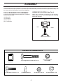
OPERATOR’S POSITION (See Fig. 1)
When right or left hand is mentioned in this manual, it
means when you are in the operating position (standing
behind tiller handles).
A socket wrench set will make assembly easier. Standard
wrench sizes are listed.
(1) Utility knife
(1) Screwdriver
(1) Pair of pliers
(2) 1/2" wrenches
overhead_views_8
FRONT
LEFT
RIGHT
OPERATOR'S POSITION
Fig. 1
CONTENTS OF HARDWARE PACK
(1) Manual
(2) Hex Bolts 5/16-18 x 1-1/4
(2) Carriage Bolts 5/16-18 UNC x 2-1/2
(1) Bottle Engine Oil
(2) Flange Locknuts
5/16-18 UNC
(2) Hex Nuts 5/16-18
4
(2) Lock Washers 5/16
ASSEMBLY
INSTALL DEPTH STAKE ASSEMBLY
(See Fig. 3)
UNPACK CARTON & INSTALL HANDLE
(See Fig. 2)
•
•
CAUTION: Be careful of exposed
staples when handling or disposing of
cartoning material.
•
IMPORTANT:
WHEN UNPACKING AND AS SEMBLING
TILLER, BE CAREFUL NOT TO STRETCH OR KINK CABLE(S).
•
•
NUT
LOCK
WASHER
HANDLE
PANEL
de
pt
NUT “A”
DEPTH STAKE
SUPPORT
STAKE
SPRING
DEPTH
STAKE
TILLER
HANDLE
HEX BOLTS,
LOCK WASHERS,
AND HEX NUTS
HEX BOLT
5/16-18X1-1/4"
L?
NE
0A
LEª
ND
HANDLE HEIGHT
•
HANDLE
PANEL
BOLTS
TILLER
HANDLES
SUPPORT
BOLT
Fig. 3
HEX BOLT
5/16-18X1"
CABLE(S)
sta
4
FLAT
WASHER
A
(
&4
ENGINE BRACKET
HALVES
h_
ke
_
1
•
Cut cable ties securing handles.
Slowly lift handle assembly up, route cable(s) as shown
and align handle holes with handle panel hole and slot.
Loosely assemble hardware as shown. Be sure the
shorter (1" long) hex bolt is assembled in lower hole
of handle. Repeat for opposite side. Tighten all
hardware securely.
Cut cable ties securing tiller to skid and remove tiller
from skid.
Remove screws securing depth stake to skid and
discard the screws.
0205
•
•
•
Loosen nut “A”.
Insert stake support between engine bracket halves
with stake spring down.
Bolt stake support to engine brackets with bolts, lock
washers and nuts. Tighten securely. Tighten nut “A”.
Depth stake must move freely. If it does not, loosen
support bolt.
Handle height may be adjusted to better suit operator.
(See “HANDLE HEIGHT” in the Service and Adjustments section of this manual).
TILLING WIDTH
•
Tilling width may be adjusted to better handle your
tilling conditions (See “TINE ARRANGEMENT” in the
Service and Adjustments section of this manual).
TINE OPERATION
•
Fig. 2
5
Check tine operation before first use. (See “TINE OPERATION CHECK” in the Service and Adjustments
section of this manual).
OPERATION
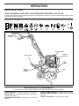
KNOW YOUR TILLER
READ THIS MANUAL AND SAFETY RULES BEFORE OPERATING YOUR TILLER.
Compare the illustrations with your tiller to familiarize yourself with the location of various controls and adjustments. Save
this manual for future reference.
These symbols may appear on your Tiller or in literature supplied with the product. Learn and understand their meaning.
FORWARD TINE
CONTROL
REVERSE TINE
CONTROL
CHOKE CONTROL
THROTTLE
CONTROL
DEPTH STAKE
TINE
SHIELD
RECOIL
STARTER
HANDLE
TINES
Fig. 4
MEETS ANSI SAFETY REQUIREMENTS
Our tillers conform to the safety standards of the American National Standards Institute.
REVERSE TINE CONTROL - Engages tines in reverse
RECOIL STARTER HANDLE - Used to start the engine.
direction.
THROTTLE CONTROL - Controls engine speed.
CHOKE CONTROL - Used when starting a cold engine.
DEPTH STAKE - Controls forward speed and the depth at
which the tiller will dig.
FORWARD TINE CONTROL - Engages tines in forward
direction.
6
OPERATION
The operation of any tiller can result in foreign objects thrown into the eyes, which can result
in severe eye damage. Always wear safety glasses or eye shields before starting your tiller and while tilling. We recommend a wide vision safety mask over spectacles or standard
safety glasses.
00155
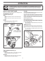
HOW TO USE YOUR TILLER
TILLING
The speed and depth of tilling is regulated by the position
of the depth stake and wheel height.
The depth stake should always be below the wheels for
digging. It serves as a brake to slow the tiller’s forward
motion to enable the tines to penetrate the ground. Also,
the more the depth stake is lowered into the ground the
deeper the tines will dig.
Know how to operate all controls before adding fuel and
oil or attempting to start engine.
STOPPING (See Fig. 5)
TINES
• Release forward tine control to stop forward movement.
• Release reverse tine control to stop reverse movement.
DEPTH STAKE (See Fig. 6)
Adjust depth stake by removing the hairpin clip and clevis
pin. Change depth stake to desired position. Replace the
clevis pin and hairpin clip.
• For normal tilling, set depth stake at the second or third
hole from the top.
ENGINE
• Move throttle control to “STOP” position.
• Never use choke to stop engine.
REVERSE TINE
CONTROL IN
“OFF” (UP)
POSITION
REVERSE TINE
CONTROL
IN “ON” (DOWN)
POSITION
FORWARD
TINE CONTROL
IN “OFF” (UP)
POSITION
WHEELS (See Fig. 6)
Adjust wheels by removing the hairpin clip and clevis pin.
Change wheel position. Replace the hairpin clip and clevis
pin.
• For normal tilling, set wheels at the second or third
hole from the top.
FORWARD TINE CONTROL
IN “ON” (DOWN) POSITION
de
pt
h_
sta
4
ke
_4
han
dle
s_9
HAIRPIN CLIP
AND CLEVIS PIN
THROTTLE
CONTROL
DEPTH
STAKE
STAKE
SPRING
CHOKE
CONTROL
WHEEL
eng
ine
_ar
t_7
1
Fig. 6
Fig. 5
TINE OPERATION (See Fig. 5)
FORWARD
• With reverse tine control in the “OFF” (up) position,
Squeeze forward tine control to handle.
REVERSE
• With forward tine control in the “OFF” (up) position,
Squeeze reverse tine control to handle.
7
OPERATION
TO TRANSPORT
CAUTION: Fill to within 1/2 inch of top
of fuel tank to prevent spills and to allow
for fuel expansion. If gasoline is accidentally spilled, move machine away
from area of spill. Avoid creating any
source of ignition until gasoline vapors
have disappeared.
Wipe off any spilled oil or fuel. Do not
store, spill or use gasoline near an
open flame.
CAUTION: Before lifting or transporting,
allow tiller engine and muffler to cool.
Disconnect spark plug wire. Drain
gasoline from fuel tank.
AROUND THE YARD
• Tip depth stake forward until it is held by the stake
spring.
• Push tiller handles down, raising tines off the ground.
• Push or pull tiller to desired location.
IMPORTANT: WHEN OPERATING IN TEMPERATURES BELOW
32°F(0°C), USE FRESH, CLEAN WINTER GRADE GASOLINE
TO HELP INSURE GOOD COLD WEATHER STARTING.
AROUND TOWN
• Disconnect spark plug wire.
• Drain fuel tank.
• Transport in upright position to prevent oil leakage.
CAUTION: Alcohol blended fuels (called
gasohol or using ethanol or methanol) can attract moisture which leads to separation and
formation of acids during storage. Acidic gas
can damage the fuel system of an engine while
in storage. To avoid engine problems, the fuel
system should be emptied before storage of
30 days or longer. Drain the gas tank, start
the engine and let it run until the fuel lines
and carburetor are empty. Use fresh fuel next
season. See Storage Instructions for additional
information. Never use engine or carburetor
cleaner products in the fuel tank or permanent
damage may occur.
BEFORE STARTING ENGINE
IMPORTANT: BE VERY CAREFUL NOT TO ALLOW DIRT
TO ENTER THE ENGINE WHEN CHECKING OR ADDING
OIL OR FUEL. USE CLEAN OIL AND FUEL AND STORE IN
APPROVED, CLEAN, COVERED CONTAINERS. USE CLEAN
FILL FUNNELS.
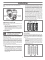
FILL ENGINE WITH OIL (See Fig. 7)
•
•
•
•
•
•
With engine level, remove engine oil filler plug.
Fill engine with oil to point of overflowing. For approximate capacity see “PRODUCT SPECIFICATIONS” on
page 3 of this manual.
Tilt tiller back on its wheels and then re-level.
With engine level, refill to point of overflowing if necessary. Replace oil filler plug.
For cold weather operation you should change oil for
easier starting (See “OIL VISCOSITY CHART” in the
Maintenance section of this manual).
To change engine oil, see the Maintenance section of
this manual.
TO START ENGINE (See Fig. 8)
CAUTION: Keep tine control in “OFF”
position when starting engine.
OIL
LEVEL
t_4
_ar
ine
eng
OIL
FILLER
PLUG
Fig. 7
ADD GASOLINE
•
Fill fuel tank to bottom of filler neck. Do not overfill.
Use fresh, clean, regular unleaded gasoline with a
minimum of 87 octane. (Use of leaded gasoline will
increase carbon and lead oxide deposits and reduce
valve life). Do not mix oil with gasoline. Purchase fuel
in quantities that can be used within 30 days to assure
fuel freshness.
8
When starting engine for the first time or if engine has run
out of fuel, it will take extra pulls of the recoil starter to
move fuel from the tank to the engine.
• Make sure spark plug wire is properly connected.
• Place throttle control in “FAST” position.
• Move choke control to full “CHOKE” position. Grasp
recoil starter handle with one hand and grasp tiller
handle with other hand. Pull rope out slowly until engine reaches start of compression cycle (rope will pull
slightly harder at this point).
• Pull recoil starter handle quickly. Do not let starter
handle snap back against starter. Repeat if necessary.
• If engine fires but does not start, move choke control
to half choke position. Pull recoil starter handle until
engine starts.
• When engine starts, slowly move choke control to
“RUN” position as engine warms up.
NOTE: A warm engine requires less choking to start.
• Move throttle control to desired running position.
• Allow engine to warm up for a few minutes before
engaging tines.
NOTE: If at a high altitude (3000 feet) or in cold
temperatures (below 32°F), the carburetor fuel mixture
may need to be adjusted for best engine performance.
See “TO ADJUST CARBURETOR” in the Service and
Adjustments section of this manual.
OPERATION
•
NOTE: If engine does not start, see troubleshooting
points.
SPARK PLUG
•
CHOKE
CONTROL
THROTTLE
CONTROL
RECOIL
STARTER
•
eng
in
e_a
r t_
71
Soil conditions are important for proper tilling. Tines will
not readily penetrate dry, hard soil which may contribute
to excessive bounce and difficult handling of your tiller.
Hard soil should be moistened before tilling; however,
extremely wet soil will “ball-up” or clump during tilling.
Wait until the soil is less wet in order to achieve the
best results. When tilling in the fall, remove vines and
long grass to prevent them from wrapping around the
tine shaft and slowing your tilling operation.
You will find tilling much easier if you leave a row untilled between passes. Then go back between tilled
rows. (See Fig. 9) There are two reasons for doing
this. First, wide turns are much easier to negotiate than
about-faces. Second, the tiller won’t be pulling itself,
and you, toward the row next to it.
Set depth stake and wheel height for shallow tilling
when working extremely hard soil or sod. Then work
across the first cuts at normal depth.
Fig. 8
BREAKING IN YOUR TILLER
Break-in your belt(s), pulleys and tine control before you
actually begin tilling.
• Start engine, tip tines off ground by pressing handles
down and engage tine control to start tine rotation.
Allow tines to rotate for five minutes.
• Check tine operation and adjust if necessary. See “TINE
OPERATION CHECK” in the Service and Adjustments
section of this manual.
3
4
5
TILLING HINTS
2
6
1
7
Fig. 9
CAUTION: Until you are accustomed
to handling your tiller, start actual field
use with throttle in slow position.
CULTIVATING
Cultivating is destroying the weeds between rows to prevent them from robbing nourishment and moisture from the
plants. At the same time, breaking up the upper layer of
soil crust will help retain moisture in the soil. Best digging
depth is 1"-3".
• You will probably not need to use the depth stake. Begin
by tipping the depth stake forward until it is held by the
stake spring.
• Cultivate up and down the rows at a speed which will
allow tines to uproot weeds and leave the ground in
rough condition, promoting no further growth of weeds
and grass (See Fig. 10).
To help tiller move forward, lift up the handles slightly (thus
lifting depth stake out of ground). To slow down the tiller,
press down on handles.
If you are straining or tiller is shaking, the wheels and depth
stake are not set properly in the soil being tilled. The proper
setting of the wheels and depth stake is through trial and
error and depends upon the soil condition. (The harder or
wetter the ground, the slower the engine and tine speed
needed. Under these poor conditions, at fast speed the
tiller will run and jump over the ground).
A properly adjusted tiller will dig with little effort from the
operator.
• Tilling is digging into, turning over, and breaking up
packed soil before planting. Loose, unpacked soil helps
root growth. Best tilling depth is 4"-6". A tiller will also
clear the soil of unwanted vegetation. The decomposition
of this vegetable matter enriches the soil. Depending
on the climate (rainfall and wind), it may be advisable
to till the soil at the end of the growing season to further
condition the soil.
9
Fig. 10
MAINTENANCE
SCHEDULE
FILL IN DATES
AS YOU COMPLETE
REGULAR SERVICE
BE
FO
RE
EA
EV
CH
ER
US
Y5
E
HO
EV
ER
UR
Y2
S
5H
EV
OU
ER
RS
Y5
0H
OU
RS
MAINTENANCE
SERVICE DATES
Check Engine Oil Level
Change Engine Oil
1,2
Oil Pivot Points
Inspect Spark Arrester / Muffler
Inspect Air Screen
Clean or Replace Air Cleaner Cartridge
2
Clean Engine Cylinder Fins
Replace Spark Plug
1 - Change more often when operating under a heavy load or in high ambient temperatures.
2 - Service more often when operating in dirty or dusty conditions.
GENERAL RECOMMENDATIONS
LUBRICATION CHART
The warranty on this tiller does not cover items that have
been subjected to operator abuse or negligence. To receive
full value from the warranty, operator must maintain tiller
as instructed in this manual.
Some adjustments will need to be made periodically to
properly maintain your tiller.
All adjustments in the Service and Adjustments section
of this manual should be checked at least once each
season.
• Once a year you should replace the spark plug, clean
or replace air filter, and check tines and belt for wear.
A new spark plug and clean air filter assure proper
air-fuel mixture and help your engine run better and
last longer.
TINE CONTROL
ENGINE
BEFORE EACH USE
•
•
•
Check engine oil level.
Check tine operation.
Check for loose fasteners.
LUBRICATION
IDLER
Keep unit well lubricated (See “LUBRICATION CHART”)
.
ARM
SAE 30 OR 10W-30 MOTOR OIL
REFER TO MAINTENANCE “ENGINE” SECTION
10
MAINTENANCE
Disconnect spark plug wire before performing any maintenance (except carburetor adjustment) to
prevent accidental starting of engine.
Prevent fires! Keep the engine free of grass, leaves, spilled oil, or fuel. Remove fuel from tank
before tipping unit for maintenance. Clean muffler area of all grass, dirt, and debris.
Do not touch hot muffler or cylinder fins as contact may cause burns.
ENGINE
LUBRICATION
engine_ar
OIL
DRAIN
PLUG
Use only high quality detergent oil rated with API service
classification SG-SL. Select the oil’s SAE viscosity grade
according to your expected temperature.
t_12
SAE VISCOSITY GRADES
SAE 30
OIL LEVEL
5W-30
-20
F
C
-30
0
-20
30
-10
32
40
0
100
80
60
10
20
OIL FILLER
PLUG
30
40
TEMPERATURE RANGE ANTICIPATED BEFORE NEXT OIL CHANGE
Fig. 11
Fig. 12
oil_visc_chart1_e
AIR CLEANER (See Fig. 13)
NOTE: Although multi-viscosity oils (5W-30, 10W-30, etc.)
improve starting in cold weather, these multi-viscosity oils
will result in increased oil consumption when used above
32°F (0°C). Check your engine oil level more frequently to
avoid possible engine damage from running low on oil.
Change the oil after every 50 hours of operation or at
least once a year if the tiller is not used for 50 hours in
one year.
Check the crankcase oil level before starting the engine
and after each five (5) hours of continuous use. Add SAE
30 motor oil or equivalent. Tighten oil filler plug securely
each time you check the oil level.
Service air cleaner cartridge every 50 hours, more often
if engine is used in very dusty conditions.
• Loosen air cleaner screws, one on each side of
cover.
• Remove air cleaner cover.
• Carefully remove air cleaner cartridge. Be careful. Do
not allow dirt or debris to fall into carburetor.
• Clean by tapping gently on a flat surface.
• If very dirty or damaged, replace cartridge.
• Clean and replace cover. Tighten screws securely.
TO CHANGE ENGINE OIL (See Figs. 11 and 12)
Determine temperature range expected before oil change.
All oil must meet API service classification SG-SL.
• Be sure tiller is on level surface.
• Oil will drain more freely when warm.
• Catch oil in a suitable container.
• Remove drain plug.
• Tip tiller forward to drain oil.
• After oil has drained completely, replace oil drain plug
and tighten securely.
• Remove oil filler plug. Be careful not to allow dirt to
enter the engine.
• Refill engine with oil. See “FILL ENGINE WITH OIL ”
in the Operation section of this manual.
CAUTION: Petroleum solvents, such as
kerosene, are not to be used to clean
cartridge. They may cause deterioration
of the cartridge. Do not oil cartridge.
Do not use pressurized air to clean or
dry cartridge.
COVER
AIR CLEANER
CARTRIDGE
AIR
CLEANER
SCREW
Fig. 13
11
MAINTENANCE
COOLING SYSTEM (See Fig. 14)
SPARK PLUG
Your engine is air cooled. For proper engine performance
and long life keep your engine clean.
• Clean air screen frequently using a stiff-bristled
brush.
• Remove blower housing and clean as necessary.
• Keep cylinder fins free of dirt and chaff.
Replace spark plugs at the beginning of each tilling season or after every 50 hours of use, whichever comes first.
Spark plug type and gap setting is shown in “PRODUCT
SPECIFICATIONS” on page 3 of this manual.
TRANSMISSION
Your transmission is sealed and will only require lubrication
if it is serviced.
CYLINDER FINS
CLEANING
MUFFLER
Do not clean your tiller when the engine and transmission
are hot. We do not recommend using pressurized water
(garden hose, etc.) to clean your unit unless the gasket
area around the transmission and the engine muffler, air
filter and carburetor are covered to keep water out. Water
in engine will shorten the useful life of your tiller.
• Clean engine, wheels, finish, etc. of all foreign matter.
• Keep finished surfaces and wheels free of all gasoline,
oil, etc.
• Protect painted surfaces with automotive type wax.
BLOWER
HOUSING
AIR SCREEN
eng
ine
_art
_71
Fig. 14
MUFFLER
Do not operate tiller without muffler. Do not tamper with
exhaust system. Damaged mufflers or spark arresters could
create a fire hazard. Inspect periodically and replace if
necessary. If your engine is equipped with a spark arrester
screen assembly, remove every 50 hours for cleaning and
inspection. Replace if damaged.
12
SERVICE AND ADJUSTMENTS
CAUTION: Disconnect spark plug wire from spark plug and place wire where it cannot come into
contact with plug.
TILLER
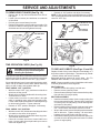
MID-WIDTH TILLING - 24 INCH PATH (See Fig. 17)
• Assemble holes “A” in tine hubs to holes “C” in tine
shaft.
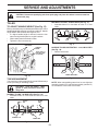
TO ADJUST HANDLE HEIGHT (See Fig. 15)
Factory assembly has provided lowest handle height. Select
handle height best suited for your tilling conditions. Handle
height will be different when tiller digs into soil.
• If a higher handle height is desired, loosen the four
nuts securing handle panel to engine brackets.
• Slide handle panel to desired location.
• Tighten the four nuts securely.
ENGINE
BRACKETS
A
C
C
A
tine_5
Fig. 17
HANDLE
PANEL
NARROW TILLING/CULTIVATING - 12-3/4 INCH PATH
(See Fig. 18)
• Remove outer tines.
NUTS (ALSO 2
ON LEFT SIDE
OF TILLER)
tine_6
INNER TINES ONLY
Fig. 15
Fig. 18
TINE ARRANGEMENT
Your outer tines can be assembled in several different ways
to suit your tilling or cultivating needs.
NOTE: When reassembling outer tines, be sure right tine
assembly (marked “R”) and left tine assembly (marked “L”)
are mounted to correct side of tine shaft.
CAUTION: Tines are sharp. Wear
gloves or other protection when handling tines.
NORMAL TILLING - 26 INCH PATH (See Fig. 16)
• Assemble holes “A” in tine hubs to holes “B” in tine
shaft.
OUTER
TINE
CLEVIS
PIN
A
A
B
B
tine_4
HAIRPIN CLIP
INNER TINE
Fig. 16
13
SERVICE AND ADJUSTMENTS
TO REMOVE BELT GUARD (See Fig. 19)
•
•
•
•
• Recheck in “ON” position and adjust if necessary.
NOTE: If “ON” position check required adjustment, recheck
“OFF” position adjustment to insure tines do not rotate when
control is “OFF” (up).
Remove two (2) cap nuts and washers from side of
belt guard.
Loosen (do not remove) tine shield nut on underside
of tine shield.
Pull belt guard out and away from unit.
Replace belt guard by reversing above procedure. Be
sure slot in bottom of belt guard is under head of tine
shield bolt and all nuts are tightened securely.
FORWARD TINE
CONTROL IN “OFF”
(UP) POSITION
BODY
han
dle
s_9
4
CAP NUTS
AND WASHERS
TINE CONTROL
“ON” POSITION
BELT
GUARD
CABLE
CLIP
TINE
CONTROL
CABLE
TINE
SHIELD
NUT
Fig. 19
TINE OPERATION CHECK (See Fig. 20)
Fig. 20
WARNING: Disconnect spark plug wire
from spark plug to prevent starting while
checking tine operation.
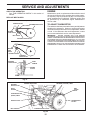
TO REPLACE V-BELTS (See Figs. 21 and 22)
Replace V-belts if they have stretched considerably or if
they show cracks or frayed edges. There are two (2) V-belts
- forward (inside) and reverse (outside).
Belt guard must be removed to service belts. See “TO
REMOVE BELT GUARD” in this section of manual.
NOTE: Observe carefully routing of both belts and location
of all belt guides before removing belts.
For proper tine operation, forward tine control lever must be
against control body and all slack removed from inner wire of
control cable when control is in the “OFF” (up) position.
If lever and cable are loose, loosen cable clip at lower end of
cable. Pull up on cable to remove slack, without extending
spring on end of cable, and retighten cable clip.
BELT REMOVAL
• Remove reverse idler pulley from idler arm.
• Remove reverse (outside) V-belt.
• Remove forward (inside) V-belt from transmission pulley
first and then from engine pulley.
FINAL CHECK “OFF” POSITION
• With tine control “OFF” (up), push down on handle to
raise tines off the ground.
• Slowly pull recoil starter handle while observing tines.
Tines should not rotate.
• If tines rotate, inner wire of control cable is too tight
which is extending lower spring and engaging tines.
Loosen cable clip and push down on cable only enough
to relieve spring tension. Tighten cable clip.
• Recheck in “OFF” position and adjust if necessary.
BELT REPLACEMENT
• Install new forward (inside) V-belt to engine pulley first
then to transmission pulley. Be sure belt is positioned
on inside groove of both pulleys, inside all belt guides
and rests on idler pulley.
• Before installing reverse (outside) V-belt, turn belt “inside
out”. Twist so wide, flat surface of belt is to inside.
• Wrap V-belt around reverse idler pulley and reassemble
idler to idler arm. Tighten securely. Be sure belt is
between reverse idler pulley and idler arm pin.
• Install belt to outside groove of transmission pulley. Be
sure belt is inside all belt guides and rests on outside
groove of engine pulley.
FINAL CHECK “ON” POSITION
• With tine control “ON” (held down to handle) push down
on handle to raise tines off the ground.
• Slowly pull recoil starter handle while observing tines.
Tines should rotate forward.
• If tines do not rotate, inner wire of control cable is too
loose. Loosen cable clip and pull cable up to remove
slack and retighten clip.
14
SERVICE AND ADJUSTMENTS
ENGINE
CHECK TINE OPERATION
• See “TINE OPERATION CHECK” in this section of
manual.
Maintenance, repair, or replacement of the emission control
devices and systems, which are being done at the customers expense, may be performed by any non-road engine
repair establishment or individual. Warranty repairs must
be performed by an authorized engine manufacturer's
service outlet.
REPLACE BELT GUARD
FORWARD MOTION (INSIDE) V-BELT
ENGINE PULLEY
TO ADJUST CARBURETOR
TRANSMISSION PULLEY
BELT GUIDE
The carburetor has been preset at the factory and adjustment
should not be necessary. However, engine performance
can be affected by differences in fuel, temperature, altitude
or load. If the carburetor does need adjustment, contact
your nearest authorized service center/department
REVERSE
IDLER PULLEY
IMPORTANT:
NEVER TAMPER WITH THE ENGINE
GOVERNOR, WHICH IS FACTORY SET FOR PROPER ENGINE
SPEED. OVERSPEEDING THE ENGINE ABOVE THE FACTORY
HIGH SPEED SETTING CAN BE DANGEROUS. IF YOU THINK
THE ENGINE-GOVERNED HIGH SPEED NEEDS ADJUSTING,
CONTACT YOUR NEAREST AUTHORIZED SERVICE CENTER/
DEPARTMENT, WHICH HAS THE PROPER EQUIPMENT AND
EXPERIENCE TO MAKE ANY NECESSARY ADJUSTMENTS.
BELT GUIDE
FORWARD IDLER PULLEY
REVERSE (OUTSIDE) V-BELT
REVERSE
IDLER
PULLEY
ENGINE PULLEY
FORWARD
IDLER PULLEY
belts 10
FRONT VIEW REFERENCE
REVERSE
IDLER PULLEY
IDLER
ARM PIN
ENGINE
PULLEY
Fig. 21
REVERSE
IDLER PULLEY
REVERSE IDLER ARM
REVERSE (OUTSIDE) V-BELT
BELT
GUARD
BOLT
IDLER
ARM PIN
FORWARD MOTION
(INSIDE) V-BELT
ENGINE PULLEY
BELT GUIDE
TRANSMISSION
PULLEY
FORWARD IDLER PULLEY
Fig. 22
15
STORAGE
Immediately prepare your tiller for storage at the end of the
season or if the unit will not be used for 30 days or more.
ENGINE OIL
Drain oil (with engine warm) and replace with clean oil. (See
“ENGINE” in the Maintenance section of this manual).
WARNING: Never store the tiller with
gasoline in the tank inside a building
where fumes may reach an open flame
or spark. Allow the engine to cool before
storing in any enclosure.
CYLINDER(S)
•
•
TILLER
•
•
•
•
•
•
Clean entire tiller (See “CLEANING” in the Maintenance
section of this manual).
Inspect and replace belts, if necessary (See belt replacement instructions in the Service and Adjustments
section of this manual).
Lubricate as shown in the Maintenance section of this
manual.
Be sure that all nuts, bolts and screws are securely
fastened. Inspect moving parts for damage, breakage
and wear. Replace if necessary.
Touch up all rusted or chipped paint surfaces; sand
lightly before painting.
•
Remove spark plug.
Pour 1 ounce (29 ml) of oil through spark plug hole
into cylinder.
Pull starter handle slowly several times to distribute
oil.
Replace with new spark plug.
OTHER
•
•
•
•
ENGINE
Do not store gasoline from one season to another.
Replace your gasoline can if your can starts to rust.
Rust and/or dirt in your gasoline will cause problems.
If possible, store your unit indoors and cover it to give
protection from dust and dirt.
Cover your unit with a suitable protective cover that
does not retain moisture. Do not use plastic. Plastic
cannot breathe which allows condensation to form and
will cause your unit to rust.
IMPORTANT: NEVER COVER TILLER WHILE ENGINE AND
EXHAUST AREAS ARE STILL WARM.
FUEL SYSTEM
IMPORTANT: IT IS IMPORTANT TO PREVENT GUM DEPOSITS
FROM FORMING IN ESSENTIAL FUEL SYSTEM PARTS SUCH
AS THE CARBURETOR, FUEL FILTER, FUEL HOSE, OR TANK
DURING STORAGE. ALSO, EXPERIENCE INDICATES THAT
ALCOHOL BLENDED FUELS (CALLED GASOHOL OR USING
ETHANOL OR METHANOL) CAN ATTRACT MOISTURE WHICH
LEADS TO SEPARATION AND FORMATION OF ACIDS DURING
STORAGE. ACIDIC GAS CAN DAMAGE THE FUEL SYSTEM
OF AN ENGINE WHILE IN STORAGE.
•
•
Drain the fuel tank.
Start the engine and let it run until the fuel lines and
carburetor are empty.
• Never use engine or carburetor cleaner products in the
fuel tank or permanent.
NOTE: Fuel stablizer is an acceptable alternative in
minimizing the formation of fuel gum deposits during
storage. Add stabilizer to gasoline in fuel tank or storage
container. Always follow the mix ratio found on stablizer
container. Run engine at least 10 minutes after adding
stablizer to allow the stabilizer to reach the carburetor.
Do not drain the gas tank and carburetor if using fuel
stabilizer.
16
TROUBLESHOOTING POINTS
PROBLEM
CAUSE
CORRECTION
1.
2.
3.
4.
5.
Out of fuel.
Engine not “CHOKED” properly.
Engine flooded.
Dirty air cleaner.
Water in fuel.
1.
2.
3.
4.
5.
6.
7.
8.
9.
Clogged fuel tank.
Loose spark plug wire.
Bad spark plug or improper gap.
Carburetor out of adjustment.
6.
7.
8.
9.
Fill fuel tank.
See “TO START ENGINE” in the Operation section.
Wait several minutes before attempting to start.
Clean or replace air cleaner cartridge.
Drain fuel tank and carburetor, and refill tank with fresh
gasoline.
Remove fuel tank and clean.
Make sure spark plug wire is seated properly on plug.
Replace spark plug or adjust gap.
Make necessary adjustments.
Hard to start
1.
2.
3.
4.
5.
6.
Throttle control not set properly.
Dirty air cleaner.
Bad spark plug or improper gap.
Stale or dirty fuel.
Loose spark plug wire.
Carburetor out of adjustment.
1.
2.
3.
4.
5.
6.
Place throttle control in “FAST” position.
Clean or replace air cleaner cartridge.
Replace spark plug or adjust gap.
Drain fuel tank and refill with fresh gasoline.
Make sure spark plug wire is seated properly on plug.
Make necessary adjustments.
Loss of power
1.
2.
3.
4.
5.
6.
7.
Engine is overloaded.
Dirty air cleaner.
Low oil level/dirty oil.
Faulty spark plug.
Oil in fuel.
Stale or dirty fuel.
Water in fuel.
1.
2.
3.
4.
5.
6.
7.
Set depth stake and wheels for shallower tilling.
Clean or replace air cleaner cartridge.
Check oil level/change oil.
Clean and regap or change spark plug.
Drain and clean fuel tank and refill, and clean carburetor.
Drain fuel tank and refill with fresh gasoline.
Drain fuel tank and carburetor, and refill tank with fresh
gasoline.
Remove fuel tank and clean.
Connect and tighten spark plug wire.
Clean engine air screen.
Clean/replace muffler.
Make necessary adjustments.
Contact an authorized service center/department.
Will not start
8.
9.
10.
11.
12.
13.
Clogged fuel tank.
Spark plug wire loose.
Dirty engine air screen.
Dirty/clogged muffler.
Carburetor out of adjustment.
Poor compression.
8.
9.
10.
11.
12.
13.
Engine overheats
1.
2.
3.
4.
5.
Low oil level/dirty oil.
Dirty engine air screen.
Dirty engine.
Partially plugged muffler.
Improper carburetor adjustment.
1.
2.
3.
4.
5.
Excessive bounce/
difficult handling
1. Ground too dry and hard.
2. Wheels and depth stake incorrectly adjusted.
1. Moisten ground or wait for more favorable soil
conditions.
2. Adjust wheels and depth stake.
Soil balls up or clumps
1. Ground too wet.
1. Wait for more favorable soil conditions.
Engine runs but tiller
won’t move
1. Tine control is not engaged.
2. V-belt not correctly adjusted.
3. V-belt is off pulley(s).
1. Engage tine control.
2. Inspect/adjust V-belt.
3. Inspect V-belt.
Engine runs but labors
when tilling
1. Tilling too deep.
2. Throttle control not properly adjusted.
3. Carburetor out of adjustment.
1. Set depth stake for shallower tilling.
2. Check throttle control setting.
3. Make necessary adjustments.
17
Check oil level/change oil.
Clean engine air screen.
Clean cylinder fins, air screen, muffler area.
Remove and clean muffler.
Adjust carburetor to richer position.
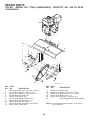
REPAIR PARTS
TILLER - MODEL NO. FT900 (96083000501), PRODUCT NO. 960 83 00-05
HANDLE ASSEMBLY
3
1
16
19
29
2
3
19
4
29
20
5
6
10
20
11
7
7
14
8
9
12
13
FT-handle_assy_5
KEY
NO.
1
2
3
4
5
6
7
8
9
10
11
PART
NO.
532 44 07-18
872 14 05-12
532 16 57-87
532 44 07-14
873 68 05-00
819 11 11-16
819 12 14-14
874 76 05-20
874 76 05-16
810 04 05-00
873 22 05-00
KEY
NO.
12
13
14
16
19
20
29
DESCRIPTION
Panel, Control
Bolt, RDHD 5/16-18 x 1 1/2
Grip, Handle
Handle, LH Double Bend
Nut, Crown Lock 5/16 -18
Washer 11/32 x 11/16 x 16 Ga.
Washer 3/8 x 7/8 x 14 Ga.
Bolt Fin Hx 5/16-18 x 1.25
Bolt Hex Hd 5/16-18 x 1
Washer Lock 5/16
Nut, FIn Hx 5/16-18
PART
NO.
898 00 01-29
532 18 08-47
532 44 07-22
532 44 07-15
532 18 85-62
532 18 85-55
812 00 00-59
DESCRIPTION
Nut, Flange
Bolt, RDHD 5/16-18 x 3/4
Assembly, Panel
Handle, RH Double Bend
Lever, Control, Tine
Pin, Pivot
Retainer, Ring
NOTE: All component dimensions given in U.S. inches.
1 inch = 25.4 mm
18
REPAIR PARTS
TILLER - MODEL NO. FT900 (96083000501), PRODUCT NO. 960 83 00-05
BELT GUARD AND PULLEY ASSEMBLY
41
1
2
3
4
17
5
30
42
6
8
7
10
29
11
31
11
29
11
12
12
9
13
11
27 28
14
15
19
26
20
25
24
16
23
22
21
32
18
belt_guard_14
KEY
NO.
PART
NO.
DESCRIPTION
1
2
3
4
5
6
7
8
9
10
11
12
13
14
15
16
17
18
19
20
532 43 91-62
532 00 94-84
532 08 67-77
874 61 08-12
873 68 06-00
819 13 13-16
532 00 20-09
532 18 03-23
874 76 06-28
532 44 07-09
819 09 10-16
532 10 42-13
872 14 04-06
532 13 30-35
532 00 26-14
812 00 00-28
532 00 26-49
532 15 12-36
532 18 85-02
812 00 00-36
Assembly, Bracket, Belt Guard
Clip, Cable
Screw #10-24 x 1/2
Bolt, Hex Head 1/2-20 x 3/4
Nut, Hex 3/8-16
Washer 13/32 x 13/16 x 16 Ga.
Pulley, Idler, Reverse
Assembly, Arm, Reverse Idler
Bolt, Hex Head 3/8-16 x 1-3/4
Guard, Belt
Washer 9/32 x 5/8 x 16 Ga.
Nut, Cap 1/4- 20
Bolt, Carriage 1/4-20 x 3/4
V-Belt (Forward Motion)
V-Belt (Reverse)
Ring, Retainer
Key, Square
Sheave, Transmission "Flat"
Bolt, Belt Guard
Ring, Klip
KEY
NO.
PART
NO.
21
22
23
24
25
26
27
28
29
30
873 35 06-00
532 16 18-06
532 17 53-77
874 76 06-20
532 10 69-68
873 35 05-00
873 22 04-00
810 04 04-00
532 10 92-27
823 20 04-04
31
32
41
42
532 10 11-89
532 15 12-23
532 18 03-07
532 13 89-09
DESCRIPTION
Nut, Hex, Jam 3/8-16
Pulley, Idler
Arm, Idler
Bolt 3/8-16 x 1-1/4
Shaft, Idler Arm
Nut, Hex, Jam 5/16-18
Nut, Hex 1/4-20
Washer, Lock 1/4
Pad, Idler
Screw, Set , Socket, Headless
C.P. 1/4-20 x 1/4
Sheave, Engine
Sheave, Transmisison
Spring Extension
Spacer
NOTE: All component dimensions given in U.S. inches.
1 inch = 25.4 mm
19
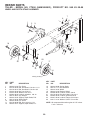
REPAIR PARTS
TILLER - MODEL NO. FT900 (96083000501), PRODUCT NO. 960 83 00-05
WHEEL AND DEPTH STAKE ASSEMBLY
WHEEL?DSTAKE?
KEY
NO.
PART
NO.
DESCRIPTION
1
2
3
4
5
6
7
8
9
10
11
13
532 00 91-94
874 76 05-20
874 76 05-12
873 22 05-00
810 04 05-00
873 80 06-00
532 12 49-61
532 00 19-52
532 12 22-33
532 00 03-26
874 78 06-28
532 00 19-51
Pin, Clevis
Bolt, Hex Head 5/16-18 x 1-1/4
Bolt, Hex Head 5/16-18 x 3/4
Nut, Hex 5/16-18
Washer, Lock 5/16
Locknut, w/washer 3/8-16
Clip, Hairpin
Support, Depth Stake, R.H.
Stake, Depth
Pin, Clevis
Bolt, Hex 3/8-16 x 1-3/4
Support, Depth Stake, L.H.
KEY
NO.
PART
NO.
DESCRIPTION
15
16
17
19
20
21
22
24
25
532 00 53-88
532 12 11-17
532 42 70-25
532 00 91-90
873 68 06-00
874 76 05-16
873 80 05-00
873 97 05-00
819 17 14-16
Spring, Stake
Bolt, Shoulder
Wheel
Bracket, Wheel
Locknut, Crown 3/8-16
Bolt, Hex Head 5/16-18 x 1
Locknut, w/insert 5/16-18
Locknut, Flange 5/16-18 unc
Washer 17/32 x 7/8 x 16 Ga.
NOTE: All component dimensions given in U.S. inches.
1 inch = 25.4 mm
20
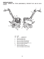
REPAIR PARTS
TILLER - MODEL NO. FT900 (96083000501), PRODUCT NO. 960 83 00-05
TINE ASSEMBLY
1
2
3
2
6
4
6
5
tine_ipb_3
KEY
NO.
PART
NO.
1
2
3
532 15 69-34
532 00 31-46
532 15 69-32
DESCRIPTION
Tine, Outer, R.H.
Retainer, Spring
Tine, Inner, R.H.
21
KEY
NO.
PART
NO.
4
5
6
532 15 69-31
532 15 69-33
532 00 49-29
DESCRIPTION
Tine, Inner, L.H.
Tine, Outer, L.H.
Rivet Pan Hd Drilled 1/4 Dia.
REPAIR PARTS
TILLER - MODEL NO. FT900 (96083000501), PRODUCT NO. 960 83 00-05
TRANSMISSION
20
1
2
3
5
6
11
19
18
17
16
8
14
11
10
7
10
14
10
12
transmission_12
KEY
NO.
PART
NO.
DESCRIPTION
1
2
3
5
6
7
8
10
11
12
874 76 05-24
874 78 06-52
819 13 13-11
873 90 06-00
532 44 07-04
532 18 81-95
532 16 58-34
873 97 05-00
532 18 79-12
532 15 12-22
Bolt, Hex 5/16-18 x 1-1/2 Gr. 2
Bolt, Hex 3/8-16 x 3-1/4
Washer 13/32 x 13/16 x 11
Locknut 3/8-16
Shield, Tine
Bracket, Engine, R.H.
Bracket, Engine, L.H.
Nut, Hex 5/16-18
Bolt, Hex Head 5/16-18 x 2.5
Transmission
KEY
NO.
PART
NO.
DESCRIPTION
14
16
17
18
19
20
532 00 91-73
819 09 14-12
819 09 20-16
810 04 04-00
874 61 04-12
-----
Spacer, Split
Washer 9/32 x 7/8 x 12 Ga.
Washer 9/32 x 1-1/4 x 16 Ga.
Washer, Lock 1/4
Bolt, Hex 1/4-28 x 3/4 Gr. 5
Engine Briggs Model 121002-1380-B8
NOTE: All component dimensions given in U.S. inches.
1 inch = 25.4 mm
22
REPAIR PARTS
TILLER - MODEL NO. FT900 (96083000501), PRODUCT NO. 960 83 00-05
DECALS
7
1
5
11
10
2
9
8
3
KEY
NO.
1
2
3
5
6
7
8
9
10
11
---
PART
NO.
532 44 06-13
532 42 20-12
532 43 99-89
532 11 06-14
532 15 87-00
532 15 87-01
532 12 00-76
532 42 29-72
532 40 91-43
532 43 22-78
532 43 99-99
532 44 00-00
DESCRIPTION
Decal, Logo
Decal, Logo
Decal, Logo
Decal, Hand Placement
Decal, Control Forward
Decal, Control Reverse
Decal, Warning, Rotating Tines
Decal, Tine Shield
Decal, Tank
Decal, Air Cleaner
Manual, Owner’s (English)
Manual, Owner’s (French)
23
6
&RQVXPHU:KHHOHG3URGXFWV±/LPLWHG:DUUDQW\
+XVTYDUQDZDUUDQWVWRWKHRULJLQDOUHWDLOSXUFKDVHUWKDWWKLV+XVTYDUQDSURGXFWLVIUHHIURPGHIHFWVLQPDWHULDORUZRUNPDQVKLS
XQGHUQRUPDOXVHDQGPDLQWHQDQFHIURPWKHGDWHRIUHWDLOSXUFKDVHIRUWKHDSSOLFDEOH:DUUDQW\3HULRGVKRZQRQ([KLELW$&HUWDLQ
FRPSRQHQWVHJHQJLQHVDQGWUDQVPLVVLRQVDUHH[FOXGHGIURPFRYHUDJHDQGRWKHUOLPLWDWLRQVDSSO\DVGHVFULEHGLQWKLVGRFXPHQW
+XVTYDUQDZLOOUHSDLURUUHSODFHDWLWVGLVFUHWLRQDQ\GHIHFWLYHSURGXFWRUSDUWFRYHUHGE\WKH/LPLWHG:DUUDQW\IUHHRIFKDUJHDWDQ\
DXWKRUL]HG +XVTYDUQD 6HUYLFLQJ 'HDOHU&HQWHU XVLQJ RULJLQDO 2(0 +XVTYDUQD UHSODFHPHQW SDUWV VXEMHFW WR WKH OLPLWDWLRQV DQG
H[FOXVLRQVGHVFULEHGEHORZ+XVTYDUQDGRHVQRWRIIHUDQRYHUWKHFRXQWHUH[FKDQJHSURJUDP
7+,6 /,0,7(' :$55$17< ,6 7+( 62/( (;35(66 :$55$17< 3529,'(' %< +8649$51$ $1< :$55$17<
7+$7 0$< %( ,03/,(' %< /$: ,1&/8',1* $1< ,03/,(' :$55$17< 2) ),71(66 )25 $ 3$57,&8/$5
385326( 25 86( $1' ,03/,(' :$55$17< 2) 0(5&+$17$%,/,7< ,6 /,0,7(' 72 7+( '85$7,21 2) 7+(
$33/,&$%/( :$55$17< 3(5,2' 81'(5 7+,6 /,0,7(' :$55$17< 7+,6 /,0,7(' :$55$17< 0$< %(
02',),(' 21/< %< +8649$51$ 620( 67$7(6 '2 127 $//2: /,0,7$7,216 21 +2: /21* $1 ,03/,('
:$55$17< /$676 62 7+( $%29( /,0,7$7,216 0$< 127 $33/< 72 <28 7+,6 /,0,7(' :$55$17< *,9(6
<2863(&,),&/(*$/5,*+76$1'<280$<$/62+$9(27+(55,*+76:+,&+9$5<)52067$7(7267$7(
7+,6:$55$17<,6*,9(121/<%<+8649$51$7+($%29(5(0(',(6$5(7+((;&/86,9(5(0(',(6)25
$1< %5($&+ 2) 7+,6 /,0,7(' :$55$17< +8649$51$ $1' ,76 $)),/,$7(' &203$1,(6 6+$// 127 %(
/,$%/( )25 $1< 63(&,$/ ,1&,'(17$/ 25 &216(48(17,$/ '$0$*( ,1&/8',1* /267 352),76 5(68/7,1*
)520$1<68&+%5($&+$1'$//68&+'$0$*(6$5(+(5(%<',6&/$,0('620(67$7(6'2127$//2:
7+((;&/86,2125/,0,7$7,212),1&,'(17$/25&216(48(17,$/'$0$*(6627+($%29(/,0,7$7,216
0$<127$33/<72<28
/,0,7$7,216$1'(;&/86,216
(QJLQHV7UDQVPLVVLRQVDQGFHUWDLQRWKHUFRPSRQHQWVDUH127FRYHUHG 7KLV/LPLWHG:DUUDQW\GRHVQRWFRYHUDQ\RIWKH
IROORZLQJ
D (QJLQHVDQG$WWDFKPHQWV([FHSWZKHUHRWKHUZLVHLQGLFDWHGRQ([KLELW$DOO(QJLQHVDQG$WWDFKPHQWVDUHQRWFRYHUHGE\
WKLVZDUUDQW\,QPRVWFDVHVWKHVHLWHPVDUH127PDQXIDFWXUHGE\+XVTYDUQDLQZKLFKFDVHWKH\PD\EHFRYHUHGVHSDUDWHO\E\
WKHLU UHVSHFWLYH PDQXIDFWXUHU¶V ZDUUDQWLHV LI RQH LV SURYLGHG DQG LQFOXGHG ZLWK WKH SURGXFW DW WKH WLPH RI SXUFKDVH $OO VXFK
FODLPV PXVW EH VXEPLWWHG DQG VHQW WR WKH DSSURSULDWH PDQXIDFWXUHU RU DV RWKHUZLVH GLUHFWHG LQ WKRVH VHSDUDWH ZDUUDQWLHV
+XVTYDUQD LV QRW DXWKRUL]HG WR KDQGOH ZDUUDQW\ DGMXVWPHQWV RUUHSDLUV RQ HQJLQHV PDQXIDFWXUHGE\ %ULJJV 6WUDWWRQ+RQGD
.DZDVDNLRU.RKOHUH[FHSWLRQ±PRGHOVHTXLSSHGZLWK/&7HQJLQHV+XVTYDUQDGRHVQRWDVVXPHDQ\ZDUUDQW\REOLJDWLRQRI
WKHRWKHUPDQXIDFWXUHU¶VHQJLQHV
E 7UDQVPLVVLRQV([FHSWZKHUHRWKHUZLVHLQGLFDWHGRQ([KLELW$7UDQVPLVVLRQ7UDQVD[OHLQFOXGLQJ'ULYH6\VWHPVDUHQRW
FRYHUHGE\WKLVZDUUDQW\,QPRVWFDVHVWKHVHLWHPVDUH127PDQXIDFWXUHGE\+XVTYDUQDLQZKLFKFDVHWKH\PD\EHFRYHUHG
VHSDUDWHO\E\WKHLUUHVSHFWLYHPDQXIDFWXUHU¶VZDUUDQWLHVLIRQHLVSURYLGHGDQGLQFOXGHGZLWKWKHSURGXFWDWWKHWLPHRISXUFKDVH
7KH IROORZLQJ WUDQVPLVVLRQ WUDQVD[OH PDQXIDFWXUHUV 'DQD +\GUR*HDU 7XII7RUT SURYLGH D ZDUUDQW\ IRU WKH WUDQVPLVVLRQ WUDQVD[OHWRWKHXOWLPDWHSXUFKDVHURUWR+XVTYDUQD+XVTYDUQDZLOODVVLJQWKHWUDQVPLVVLRQWUDQVD[OHPDQXIDFWXUHU¶VZDUUDQW\
RU DQ\ULJKWV WKHUHRI WR WKHRULJLQDOSXUFKDVHU RI WKHXQLW 7RREWDLQ WUDQVPLVVLRQ WUDQVD[OH ZDUUDQW\ VHUYLFH ILUVWFRQWDFW WKH
UHWDLOHUZKR\RXSXUFKDVHGWKHXQLWIURP6KRXOG\RXUHTXLUHDVVLVWDQFHRUKDYHDQ\TXHVWLRQVFRQFHUQLQJWUDQVPLVVLRQWUDQVD[OH
ZDUUDQW\ FRYHUDJH FRQWDFW +XVTYDUQD GLUHFWO\ DW RXU ZHEVLWH ZZZKXVTYDUQDFRP RU FDOO IRU DQ DXWKRUL]HG
+XVTYDUQDVHUYLFHSURYLGHU$OOVXFKFODLPVPXVWEHVXEPLWWHGDQGVHQWWRWKHDSSURSULDWHPDQXIDFWXUHURUDVRWKHUZLVHGLUHFWHG
LQWKRVHVHSDUDWHZDUUDQWLHV+XVTYDUQDLVQRWDXWKRUL]HGWRKDQGOHZDUUDQW\DGMXVWPHQWVRUUHSDLUVRQWUDQVPLVVLRQVRUWUDQVD[OHV
+XVTYDUQDGRHVQRWDVVXPHDQ\ZDUUDQW\REOLJDWLRQRIWKHDERYHOLVWHGPDQXIDFWXUHUVIRUH[FHSWLRQV±VHH([KLELW$
F ([SHQGDEOH 3DUWV 7KLV /LPLWHG :DUUDQW\ GRHV QRW FRYHU JHQHUDO PDLQWHQDQFH SDUWV DQG LWHPV ³([SHQGDEOH 3DUWV´
LQFOXGLQJZLWKRXWOLPLWDWLRQVSDUNSOXJVEXOEVILOWHUVOXEULFDQWVVWDUWHUFRUGVEHOWVEODGHVDQGEODGHDGDSWHUV
G (PLVVLRQV&RQWURO&RPSRQHQWV7KLV/LPLWHG:DUUDQW\GRHVQRWFRYHU(PLVVLRQVFRQWUROHTXLSPHQWDQGFRPSRQHQWVWRWKH
H[WHQW UHJXODWHG E\ WKH86(QYLURQPHQWDO 3URWHFWLRQ$JHQF\ RU VLPLODU VWDWH DJHQFLHV 6XFK HTXLSPHQW DQG FRPSRQHQWV DUH
FRYHUHGE\DVHSDUDWHHPLVVLRQFRQWUROZDUUDQW\VWDWHPHQWVXSSOLHGZLWK\RXUQHZSURGXFW3OHDVHFRQVXOWWKLVVHSDUDWHZDUUDQW\
VWDWHPHQWIRUGHWDLOV
$Q\ &200(5&,$/ ,16,787,21$/ $*5,&8/785$/ ,1'8675,$/ ,1&20( 352'8&,1* RU 5(17$/ XVH ZLOO UHVXOW LQ HLWKHU 1R
:DUUDQW\RUD6KRUWHQHG:DUUDQW\3HULRG'HSHQGLQJRQWKHSURGXFWWKHUHLVHLWKHU12:$55$17<RUDUHGXFHGZDUUDQW\LIWKHSURGXFWLVXVHGIRUFRPPHUFLDO
LQVWLWXWLRQDODJULFXOWXUDOLQGXVWULDOLQFRPHSURGXFLQJRUUHQWDOSXUSRVHV3OHDVHUHIHUWR([KLELW$
2ZQHU¶V<RXU5HVSRQVLELOLWLHV7RSUHVHUYH\RXUULJKWVXQGHUWKLV/LPLWHG:DUUDQW\\RXPXVWGHPRQVWUDWHUHDVRQDEOHFDUH
DQGXVHRIWKHSURGXFWLQFOXGLQJIROORZLQJWKHSUHYHQWDWLYHPDLQWHQDQFHVWRUDJHIXHODQGRLOXVDJHVDVSUHVFULEHGLQWKHHQFORVHG
RSHUDWRU¶VPDQXDO)RUH[DPSOHWKHIROORZLQJLWHPVDUHWKH2ZQHU¶VUHVSRQVLELOLW\DQGDUHQRWFRYHUHGE\WKLV/LPLWHG:DUUDQW\
D 6HWXSDQGSUHGHOLYHU\VHUYLFHDQGHQJLQHWXQHXSV
E $GMXVWPHQWVDIWHUWKHILUVWWKLUW\GD\VRISXUFKDVHDQGEH\RQGVXFKDVWKURWWOHFDEOHEHOWJXLGHVDGMXVWPHQWV
24
F 3UHYHQWDWLYHPDLQWHQDQFHDVRXWOLQHGLQWKHRSHUDWRU¶VPDQXDO
,QDGGLWLRQ\RXPXVWFHDVHXVLQJWKHSURGXFWLPPHGLDWHO\XSRQDQ\IDLOXUHRUGDPDJH7KHSURGXFWVKRXOGEHWDNHQWRDQDXWKRUL]HG
+XVTYDUQDVHUYLFLQJGHDOHUSULRUWRDQ\IXUWKHUXVH
'DPDJHV UHVXOWLQJ IURP QRUPDO DJLQJ ZHDU DQG WHDU RU QHJOHFW DUH 127 FRYHUHG 7KH /LPLWHG :DUUDQW\ GRHV QRW FRYHU
GDPDJH RWKHU WKDQ WKDW UHVXOWLQJ IURP GHIHFWV LQ PDWHULDO RU ZRUNPDQVKLS 7KH IROORZLQJ DUH 127 FRQVLGHUHG GHIHFWV LQ PDWHULDO RU
ZRUNPDQVKLSDQGWKHUHIRUHDUH127FRYHUHG
D $EUDVLRQWRPRZHUGHFNV
E 7LUHVGDPDJHGE\H[WHUQDOSXQFWXUHV
F 1DWXUDOGLVFRORUDWLRQRIPDWHULDOVGXHWRXOWUDYLROHWOLJKW
G 'DPDJHWRFXWWLQJHTXLSPHQWE\ZD\RIFRQWDFWZLWKURFNVRURWKHUQRQDSSURYHGPDWHULDOVDQGRUVWUXFWXUHV
,QDGGLWLRQWKLV/LPLWHG:DUUDQW\GRHVQRWFRYHUGDPDJHVPDOIXQFWLRQVRUIDLOXUHVUHVXOWLQJIURPDEXVHRUQHJOHFWRIWKHSURGXFW
UHODWHGWRRULQFOXGLQJDQ\RIWKHIROORZLQJ
H )DLOXUHWRSURYLGHRUSHUIRUPUHTXLUHGPDLQWHQDQFHVHUYLFHVDVSUHVFULEHGLQWKHRSHUDWRU¶VPDQXDO
I
$EXVHPLVXVHQHJOHFWPRGLILFDWLRQVDOWHUDWLRQVQRUPDOZHDULPSURSHUVHUYLFLQJXVHRIXQDXWKRUL]HGDWWDFKPHQWV/DFNRI
OXEULFDWLRQRUHQJLQHIDLOXUHGXHWRWKHXVHRIRLOVWKDWGRQRWPHHW(QJLQHPDQXIDFWXUHU¶VVSHFLILFDWLRQV
J 8VH RI JDVRKRO FRQWDLQLQJ PHWKDQRO ZRRG DOFRKRO *DVRKRO ZKLFK FRQWDLQV D PD[LPXP HWKDQRO JUDLQ DOFRKRO RU
07%(PHWK\OWHUWLDU\EXW\OHWKHULVDSSURYHG
K 8VHRIHWKHURUDQ\VWDUWLQJIOXLGV
L
3UHVVXUHFOHDQLQJRUVWHDPFOHDQLQJWKHSURGXFW
M
8VHRIVSDUNSOXJVRWKHUWKDQWKRVHPHHWLQJHPLVVLRQSHUIRUPDQFHUHTXLUHPHQWVOLVWHGLQWKHRSHUDWRU¶VPDQXDO
N 7DPSHULQJ ZLWK HQJLQH VSHHG JRYHUQRU RU HPLVVLRQ FRPSRQHQWV RU UXQQLQJ HQJLQHV DERYH VSHFLILHG DQG UHFRPPHQGHG
HQJLQHVSHHGVDVOLVWHGLQ\RXURSHUDWRU¶VPDQXDO
O
2SHUDWLRQRIWKHXQLWZLWKLPSURSHUO\LQVWDOOHGUHPRYHGRUPRGLILHGFXWWLQJVKLHOGVJXDUGVRUVDIHW\GHYLFHV
P $Q\ UHPRYHGGDPDJHG DLU ILOWHU H[FHVVLYH GLUW DEUDVLYHV VDOW ZDWHU PRLVWXUH FRUURVLRQ UXVW YDUQLVK VWDOH IXHO RU DQ\
DGYHUVHUHDFWLRQGXHWRLQFRUUHFWVWRUDJHSURFHGXUHV
Q )DLOXUHV GXH WR LPSURSHU VHW XS SUHGHOLYHU\ VHUYLFH RU UHSDLU VHUYLFH E\ DQ\RQH RWKHU WKDQ DQ DXWKRUL]HG +XVTYDUQD
VHUYLFLQJGHDOHUGXULQJWKHZDUUDQW\SHULRG
R 'LUW FRQWDPLQDWHG JUHDVH RU RLO XVH RI LQFRUUHFW W\SH RI JUHDVHV RU RLOV IDLOXUH WR FRPSO\ ZLWK UHFRPPHQGHG JUHDVLQJ
LQWHUYDOVZDWHURUPRLVWXUHGDPDJHDQGRULPSURSHUVWRUDJH
S 6SUD\HUVSXPSLQJRUVSUD\LQJFDXVWLFRUIODPPDEOHPDWHULDOVODFNRIRUEURNHQVWUDLQHUVRU
T &RQWLQXHGXVHRISURGXFWDIWHULQLWLDORSHUDWLRQDOSUREOHPRUIDLOXUHRFFXUV
+2:722%7$,16(59,&(
$XWKRUL]HG +XVTYDUQD 6HUYLFLQJ 'HDOHU&HQWHU ,Q RUGHU WR REWDLQ ZDUUDQW\ FRYHUDJH LW LV \RXU UHVSRQVLELOLW\ DW \RXU
H[SHQVHWRGHOLYHURUVKLS\RXU+XVTYDUQDXQLWWRDQDXWKRUL]HG+XVTYDUQD6HUYLFLQJ'HDOHU&HQWHUDQGDUUDQJHIRUSLFNXSRUUHWXUQ
RI\RXUXQLWDIWHUWKHUHSDLUVKDYHEHHQPDGH,I\RXGRQRWNQRZWKHORFDWLRQRI\RXUQHDUHVWDXWKRUL]HG+XVTYDUQD6HUYLFLQJ'HDOHU
FDOO+XVTYDUQDDWGXULQJWKHKRXUVRI$0WR30(DVWHUQ6WDQGDUG7LPHRUYLVLWZZZKXVTYDUQDFRP
6KRXOG\RXUHTXLUHDVVLVWDQFHRUKDYHTXHVWLRQVFRQFHUQLQJWKLV/LPLWHG:DUUDQW\\RXPD\FRQWDFWXVDWGXULQJWKH
KRXUVRI$0WR30(DVWHUQ6WDQGDUG7LPHRUFRQWDFWXVWKURXJKWKHZHEDWZZZKXVTYDUQDFRP
'RFXPHQWDWLRQ5HTXLUHG<RXPXVWPDLQWDLQDQGSUHVHQW3URRIRISXUFKDVHLQFOXGLQJGDWHSURGXFWPRGHODQGLIDSSOLFDEOH
HQJLQH VHULDO QXPEHU WR DQ DXWKRUL]HG +XVTYDUQD 6HUYLFLQJ 'HDOHU IRU ZDUUDQW\ VHUYLFH XQGHU WKLV /LPLWHG :DUUDQW\ 3URRI RI
SXUFKDVH UHVWV VROHO\ ZLWK WKH RZQHUFXVWRPHU +XVTYDUQD HQFRXUDJHV \RX WR UHJLVWHU \RXU SURGXFW RQOLQH DW
ZZZXVDKXVTYDUQDFRP WR KHOS HQVXUH DPRQJ RWKHU WKLQJV WKDW \RX FDQEHQRWLILHGRI LPSRUWDQW SURGXFW LQIRUPDWLRQ +RZHYHU
UHJLVWHULQJ\RXUSURGXFWLVQRWDFRQGLWLRQRIZDUUDQW\VHUYLFH
+XVTYDUQD&RQVXPHU2XWGRRU3URGXFWV1$,QF+XVTYDUQD3URIHVVLRQDO3URGXFWV,QF
+DUULV&RUQHUV3DUNZD\&KDUORWWH1&
25
5
&RQVXPHU:KHHOHG:DUUDQW\&KDUW
([KLELW$
&RQVXPHU SHUVRQDO
KRXVHKROGXVHRQO\
3URGXFW&RPSRQHQW
5LGLQJ/DZQ7UDFWRUV
)UDPH&KDVVLV)URQW$[OH
(QJLQH
7UDQVPLVVLRQLIPDGHE\
+XVTYDUQD3HHUOHVV
7UDQVPLVVLRQLIWKLUGSDUW\
%DWWHU\
2WKHU1RQ([SHQGDEOH&RPSRQHQWV
5HVLGHQWLDO=HUR7XUQ0RZHUV 5=2QO\ (QJLQH
7UDQVPLVVLRQ
%DWWHU\
2WKHU1RQ([SHQGDEOH&RPSRQHQWV
5HVLGHQWLDO=HUR7XUQ0RZHUV 0=(= (QJLQH
7UDQVPLVVLRQ
%DWWHU\
2WKHU1RQ([SHQGDEOH&RPSRQHQWV
/((GJHU
(QJLQH
2WKHU1RQ([SHQGDEOH&RPSRQHQWV
:DON%HKLQG0RZHUV
(QJLQH
%DWWHU\
2WKHU1RQ([SHQGDEOH&RPSRQHQWV
6QRZ7KURZHUV
(QJLQH
2WKHU1RQ([SHQGDEOH&RPSRQHQWV
7LOOHUV
(QJLQH
%DWWHU\
2WKHU1RQ([SHQGDEOH&RPSRQHQWV
7LOOHU7LQHV
+RYHULQJ7ULPPHUV
(QJLQH
2WKHU1RQ([SHQGDEOH&RPSRQHQWV
&RPPHUFLDO DQ\FRPPHUFLDO 5HQWDO DQ\UHQWDO
SURIHVVLRQDOLQVWLWXWLRQDO
XVDJH
DULJFXOXWUDORULQFRPHSURGXFLQJ
XVHRWKHUWKDQ5HQWDO8VH
<HDUV
12:$55$17<
12:$55$17<
<HDUV
<HDU3URUDWHG
<HDUV
12:$55$17<
12:$55$17<
12:$55$17<
12:$55$17<
12:$55$17<
12:$55$17<
<HDU3URUDWHG
<HDUV
12:$55$17<
12:$55$17<
12:$55$17<
12:$55$17<
12:$55$17<
12:$55$17<
<HDU3URUDWHG
<HDUV
<HDU3URUDWHG
<HDU
12:$55$17<
12:$55$17<
<HDUV
GD\V
GD\V
<HDU3URUDWHG
<HDUV
12:$55$17<
12:$55$17<
12:$55$17<
12:$55$17<
<HDUV
GD\V
GD\V
<HDU3URUDWHG
<HDUV
12:$55$17<
12:$55$17<
12:$55$17<
12:$55$17<
12:$55$17<
12:$55$17<
<HDUV
<HDU
&RQVXPHU
&RPPHUFLDO
6HH6HSDUDWH(QJLQH0DQXIDFWXUHU
VRU0DQXIDFWXUHU
VZDUUDQW\
/&7(QJLQHVRQVSHFLILF6QRZ7KURZHUV7LOOHUVZDUUDQW\WKURXJK+XVTYDUQD
6HHUHIHUHQFHERIWKHZDUUDQW\VWDWHPHQW
5=7ZR<HDU&RQVXPHUZDUUDQW\SDUWVODERUZLWK+\GUR*HDU'LVWULEXWRUQHWZRUN
(=2QH<HDU&RPPHUFLDOZDUUDQW\SDUWVODERUZLWK+XVTYDUQD
7ZR<HDU&RQVXPHUZDUUDQW\SDUWVODERUZLWK+\GUR*HDU'LVWULEXWRUQHWZRUN
0=7ZR<HDU&RPPHUFLDOZDUUDQW\SDUWVODERUZLWK+\GUR*HDU'LVWULEXWRUQHWZRUN
GD\V
5HQWDO
/LPLWHG/LIHWLPH:DUUDQW\RQ7LOOHUWLQHVLVIRUWKHOLIHRIWKHSURGXFWRUVHYHQ\HDUVDIWHUWKHODVWGDWHRIWKHFRPSOHWH
XQLW
VILQDOSURGXFWLRQZKLFKHYHUFRPHVILUVW
26
&RQVXPHU:KHHOHG:DUUDQW\&KDUW
([KLELW$
&RQVXPHU SHUVRQDO
KRXVHKROGXVHRQO\
&RPPHUFLDO DQ\FRPPHUFLDO 5HQWDO DQ\UHQWDO
SURIHVVLRQDOLQVWLWXWLRQDO
XVDJH
DULJFXOXWUDORULQFRPHSURGXFLQJ
XVHRWKHUWKDQ5HQWDO8VH
3URGXFW&RPSRQHQW
)URQW0RXQWHG'HFN5LGHUV
(QJLQH
7UDQVPLVVLRQ
<HDUV
12:$55$17<
%DWWHU\
<HDU3URUDWHG
12:$55$17<
2WKHU1RQ([SHQGDEOH&RPSRQHQWV
<HDUV
12:$55$17<
&XOWLYDWRUV
%DWWHU\
<HDU3URUDWHG
12:$55$17<
2WKHU1RQ([SHQGDEOH&RPSRQHQWV
<HDUV
12:$55$17<
3UHVVXUH:DVKHUV
0RGHO3:
(QJLQH
3XPS
<HDUV
12:$55$17<
2WKHU1RQ([SHQGDEOH&RPSRQHQWV
<HDUV
12:$55$17<
$OORWKHU3UHVVXUH:DVKHUV3:3:3:
(QJLQH
3XPS
<HDUV
<HDUV
2WKHU1RQ([SHQGDEOH&RPSRQHQWV
<HDUV
<HDUV
*HQHUDWRUV
(QJLQH
<HDUVQG<HDU
<HDUV*1QG<HDU
3DUWV2QO\
3DUWV2QO\
2WKHU1RQ([SHQGDEOH&RPSRQHQWV
6SUHDGHUV
6SUHDGHU
<HDU
<HDU
5RERWLF0RZHUV
5RERWLF0RZHU
<HDUV
GD\V
%DWWHU\
<HDU
<HDU
3DUWV$FFHVVRULHVLISXUFKDVHG
3
W $
L LI
K
G
$FFHVVRULHVHJJUDVVFDWFKHUEXPSHU
JXDUGDFFHVVRULHVHWF
<HDU
12:$55$17<
3DUWVHJEHOWVEODGHVHWF
GD\V
12:$55$17<
3DUWV$FFHVVRULHVLIUHSODFHGLQ:DUUDQW\6HUYLFH
5HSODFHPHQWSDUWVDQGRUDFFHVVRULHV
SURYLGHGXQGHUWKLV/LPLWHG:DUUDQW\DUH
ZDUUDQWHGRQO\IRUWKH%$/$1&(RIWKH
ZDUUDQW\SHULRGDSSOLFDEOHWRWKHSDUWRU
DFFHVVRU\WKDWZDVUHSODFHG
6HHWROHIW
6HHWROHIW
&RQVXPHU
&RPPHUFLDO
6HH6HSDUDWH(QJLQH0DQXIDFWXUHU
VRU0DQXIDFWXUHU
VZDUUDQW\
/&7(QJLQHVRQVSHFLILF6QRZ7KURZHUV7LOOHUVZDUUDQW\WKURXJK+XVTYDUQD
6HHUHIHUHQFHERIWKHZDUUDQW\VWDWHPHQW
5=7ZR<HDU&RQVXPHUZDUUDQW\SDUWVODERUZLWK+\GUR*HDU'LVWULEXWRUQHWZRUN
(=2QH<HDU&RPPHUFLDOZDUUDQW\SDUWVODERUZLWK+XVTYDUQD
7ZR<HDU&RQVXPHUZDUUDQW\SDUWVODERUZLWK+\GUR*HDU'LVWULEXWRUQHWZRUN
0=7ZR<HDU&RPPHUFLDOZDUUDQW\SDUWVODERUZLWK+\GUR*HDU'LVWULEXWRUQHWZRUN
12:$55$17<
12:$55$17<
12:$55$17<
12:$55$17<
12:$55$17<
12:$55$17<
12:$55$17<
12:$55$17<
12:$55$17<
12:$55$17<
<HDU
GD\V
<HDU
12:$55$17<
12:$55$17<
6HHWROHIW
5HQWDO
/LPLWHG/LIHWLPH:DUUDQW\RQ7LOOHUWLQHVLVIRUWKHOLIHRIWKHSURGXFWRUVHYHQ\HDUVDIWHUWKHODVWGDWHRIWKHFRPSOHWH
XQLW
VILQDOSURGXFWLRQZKLFKHYHUFRPHVILUVW
27
11.29.10 CL
Printed in the U.S.A.