1
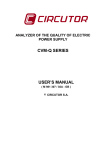
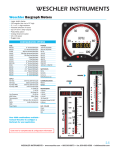
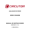
SERIES 4000
ENERGY METER
WATT WATCHER
INSTALLATION AND OPERATION MANUAL
HOYT ELECTRICAL INST. WORKS INC.
PENACOOK, NEW HAMPSHIRE
PHONE 800-258-3652
www.hoytmeter.com
INDEX
Short Cut to Resetting the Demand Readings
.
Inside Front Cover
Introduction
1.
Main Features
2.
The Meter Terminal Description
3.
Wiring Diagrams
4.
Wiring Instructions
5.
Solid Core Current Transformers
5.
Split Core Model “TP” Current Transformers
6.
Split Core Model “1250” Current Sensors
7.
Common Terms Used in Metering
8.
Specifications
9.
Communications
10.
ModBus Protocol
11.
Trouble Shooting
12.
Warranty
Back Cover
INTRODUCTION:
You now have in your possession one of the most reliable and highly accurate meters ever
manufactured.
To insure proper installation and performance please take the time to read this manual before
installing this meter. The installation information contained within this manual is to be used as a
guide and any applicable electrical codes must take precedence over the information contained
within.
**WARNING**
We recommend that all electrical circuits that you are working on be DE-ENERGIZED prior to
installation of this meter or current transformers. If this is not possible than any and all
applicable OSHA Safety Rules, Union Safety Rules or any other applicable safety rules when
working with energized circuits must be adhere to. A license electrician must perform this
installation for all applicable warrantees to be in effect.
The Series 4000 kit is made up of 4 components; 1 meter and 3 CTs. Solid core CTs up to 400
Amps are included in the standard kit, with larger sizes and split core CTs as an option. The line
wires feeding this meter shall be protected with in-line 5 Amp fuses or a 15-Amp 3-pole circuit
breaker. Most all of our current transformers have a 5 Amp at F.L. secondary output. Never
leave the black and white wires open when the meter is out of service. There is an
appreciable voltage depending on the rating of the CT and the primary load. An open CT will
hum and vibrate in larger sizes.
CHECK FOR SHIPPING DAMAGE and SHORTAGES
The Watt Watcher Meters are shipped in a protective box with the solid core CTs. Split Core
CTs may be in another box. After unpacking your meter please check for obvious damage or if
any components are missing. In either case promptly notify the distributor where it was
purchased.
ERRORS AND OMISSIONS:
We have taken all precautions to create a complete installation manual. NMI is not liable for any
omissions or errors contained within. Please contact us if you have any questions after reading
through this manual. Thank You.
NOTE TO THE ELECTRICIAN: PLEASE LEAVE THIS MANUAL WITH THE
METER WHEN LEAVING. THANK YOU!
1.
MAIN FEATURES:
The Series 4000 is factory programmed offering one model for both 3 or 4 wire services or
branch circuits. The factory has program the Amperage, and a 15-min. demand period (KW4000
only), according to the distributors purchase order.
There are six (6) kWh digits across the top section of the display, which are the kilowatt-hours
accumulated. There are no resets available for kWhs, like a utility meter and there are no
multipliers needed to read the energy consumed. There are three additional readings along the
bottom of the display. These readings are three digits of voltage, three digits of amperage and
three digits of instantaneous kilowatts. These power readings will display “HI” when the
readings go to 4 digits i.e., 1000 Amps or kW.
The Series 4000 Demand Meter (Model KW4000) will scroll to Maximum Demand (pd). The
demand interval is factory set at 15 minutes unless otherwise instructed. Sliding or Rolling
Window is the demand method used by this meter.
The factory programs the relay to1-KWhr per pulse, as a standard unless otherwise instructed.
There is a RS485 ModBus terminal next to the relay. This port works with our Intelligent
Converter that plugs into the RS232 Com Port in your computer. NMI offers software programs.
Call the factory for more information.
The voltage and the current terminals are removable. If a field calibration check is necessary the
terminals simply unplug and a portable meter tester can plug into them. These terminals are a
standard feature on all of our meters. Also the CTs have two extra terminals that are used when
paralleling two sets of CTs. Remember Current Sensors with voltage outputs cannot be
paralleled. Voltage is not additive in parallel, where current is.
There are holes in each corner of the meter for mounting the meter against a plywood board,
sheet rock wall or switch boards. We don’t recommend that the meters be mounted against a
concrete wall. If there are any technical questions that this manual does not cover please call our
technical desk at (603) 753-6321.
2.
THE SERIES 4000 CONNECTION TERMINALS
Terminal No.
Designation
Description
L1 – L2
Power Supply
Power Supply at 230 or 480 VAC
Relay
Pulse
Reed Relay
RS 485
ModBus Protocol
RS485 Daisy Chains to other meters
N
N
Neutral
L1
Measuring Voltage
Voltage signal from Phase L1
L2
Measuring Voltage
Voltage signal from Phase L2
L3
Measuring Voltage
Voltage signal from Phase L3
CT1 B&W
Current Transformer
Current or milli-volt signal from CT1
CT2 B&W
Current Transformer
Current or milli-volt signal from CT2
CT3 B&W
Current Transformer
Current or milli-volt signal from CT3
Note:
Color-code and size all wires according to National Electric Code.
Current Transformer wires shall be twisted to cancel noise.
Current Transformers and Line Voltage shall be phase related i.e., L1 and CT1 from the same
phase the same with L2 and L3.
3.
CONNECTION DIAGRAMS FOR THE SERIES 4000
Three Phase 4 wire service, which also includes a Hi-leg Service.
1. Use either 5 Amp in-line fuses or a 15 Amp CB with lock
2. RS485 Terminals (+ GRN - ) optional
3. Relay 1 pulse relay
B. Three Phase 3 wire: (either a delta or 3 wires of a 4 wire service)
1.
2.
3
5 Amp in-line fuses or 15 Amp CB with lock
RS485 Terminals (+ GRN - ) optional
Relay 1 pulse relay
4.
WIRING INSTRUCTIONS
1. All wiring to this meter must comply with National Electric Code or any local codes that are
applicable. A grounding conductor must be installed and connected to the ground lug located
under the terminal cover in the meter.
2. The voltage wires connected to the line terminals in the meter can be No. 14 gage. The load
for the meter is .03 Amps. Either 5 Amp in-line fuses or a 15 Amp circuit breaker with a
locking handle should protect the voltage leads.
3. The extended wires from the meter to the current transformers can be #16 gauge stranded
wire up to 100’and 14 to 200’ distance. The voltage and the current wires can be in the same
conduit, if you twist the current wires. The CT leads must be shunted if the CT is to be
installed before the meter arrives, or if the meter is taken out of service. Never leave the CT
leads open on an energized circuit drawing current. Exception is the NMI-1250 split core
current sensors. The secondary output of this split core is 110 mv, not current. In this case
the black and white wires are capped separately if meter is not connected.
4. Form all wires neatly within the field termination area provided. An extra row of CT
terminals are provided if paralleling is required. Both the voltage and the current terminals
are removable if field-testing is required in the future.
Please check carefully all
connections before energizing meter.
Solid Core Current Transformers
1. Solid Core CTs up to 400 Amps is supplied with this meter. The LX 400 Amp CT works in
a range of 4 to 400 Amp. The solid core CTs are more accurate than the split core and are
much smaller. Split Cores are available if the power cannot be turned off. The (H1) or white
dot, depending on the manufacture, faces the line side of the service.
The black wire connects to the CT terminal (B) and the white wire connects to CT terminal (W).
Note: Shunt the black and white wires if the CT is installed and the meter has not been connected. Twist the
black and white wires independently from each CT.
5.
Split Core Current Transformers (Model NMI-TP-Series)
Please refer to the above drawing:
1. Remove and dispose of the packaging materials
2. To remove the end piece, unscrew the assembly nuts, push in on the end piece to
relieve the pressure on the bolts. Pull the bolts out and pull the end from the main U
shaped housing.
3. Position the “P1” side of the CT towards the line side of the service.
4. There are 2 screw pressure terminals labeled “S1” and “S2”. Connect the white
common 5 Amp wire to the “S2” terminal and black wire which is to the “S1” terminal.
5. The other two brass screws can be used for shunting out the CT with the use of a jumper, if
needed. Remember to remove the jumper after connecting the CT to the meter. Do not put
the CT around an energized conductor unless the CT is shunted or connected to the meter. A
open CT will vibrate and hum.
CAUTION: NMI RECOMMENDS THAT YOU TURN OFF ALL POWER BEFORE
INSTALLING CTS.
6.
Split Core Current Sensor Model (NMI 1250-400)
The secondary side of these split core transformers is 110 milli-volts at 400 Amps.
You need to cap the black and white wires separately if the meter is not installed at the time the
current sensor is working.
Pull hard on the bottom section to open the yoke of the sensor. Install around conductor and
snap back together. Twist the black and white wires independently from each sensor. The
sensor wires and the voltage wires can be installed in the same conduit. You can run up to 2000’
with #16 gage wire.
OPERATION MODE OF THE SERIES 4000
Front Panel of the Series K4000
1. The Display has Six kWh 5/16th Digits across the top and three 3/16th digits for Volts, Amps.
and (instantaneous) kW No multipliers are needed to read the energy.
2. If Amps and kW are over 999 the display will show “HI”
3. The RATE LED will blink every time one-Kilowatt hour is consumed
7.
COMMON TERM USED WITH METER READINGS
VOLTAGE: The potential between phase and neutral or phase to phase. This can be 120 to 480 volts depending
upon the model selected.
AMPERE: A unit of electrical current, which will flow through a resistance of 1 ohm by 1 volt.
WATTS: A unit of active power, which is defined as the rate at which energy is delivered to a circuit. This is the
power expanded when a current of one Ampere flows through a resistance of one ohm.
kW: A common abbreviation for 1000 watts.
KW DEMAND: A measurement of energy (kW) or (KVA) over a choice of a time interval in 15 or 30 minutes,
which is most common. A thumb rule method is to count kWh in 15 minutes and multiply by four. Multiply by two
if the demand interval is 30 minutes.
ROLLING OR SLIDING WINDOW: A demand interval that moves in time through a sub-interval. One
example would be a 15-minute demand interval could comprise of 15 one-minute sub-intervals. The first 1-minute
sub-interval will slide into the next measuring period, dropping the last sub-interval. This is the method used in this
meter, and by many utility companies.
WATT-HOUR: A unit of electric energy that measures one watt in one hour. There are one thousand-watt hours in
one-kilowatt hour.
HERTZ: A practical unit measuring the number of positive and negative values occurring in one second. Sixty Hz
is typical in the US and fifty is used in Europe.
VOLT-AMPERE: A unit of volts and current that flows because of the voltage. Volt-ampere and kilowatts are the
same at unity power factor. In an AC circuit with power factor other than unity the VA equal the square root of watts
squared plus reactive volt-amperes squared. The greater the VA over kW is reflected by poor power factor.
KVA: A common abbreviation for 1000 volt-amperes.
POWER FACTOR: The ratio of active power (kW) to apparent power (KVA). Power Factor (PF) can be corrected
by capacitors or synchronies motors.
THD and D (TOTAL HARMONIC DISTORTION and Distortion):
Lets defined linear and non-liner loads. From a simple and practical point of view, a linear load is that, when
supplied by a sinusoidal voltage, absorbs also a sinusoidal current. On the contrary, a non-linear load will absorb a
non-sinusoidal current for the same supply voltage, although such current is habitually of periodical type.
Representative examples are Static power converters, AC to DC power supplies, Discharge lamp lighting, Arc
furnaces, electric welding machines, Transformers, Iron core reactors, etc.
The Distortion can be measured in two different ways, giving parameters known as “d” and “THD”. THD rate is
referred to the total R.M.S. value where as d is obtained by multiplying a fundamental voltage by a series of currents
with frequencies multiple of the fundamental frequency.
Expected distortion rates commonly found in power systems are 5% and below in voltage and 30% and lower in
current. Higher readings do not necessarily mean a faulty facility but should be looked at for a potential problem.
PULSE OUTPUTS: Each pulse represents a predetermined increment of power or other quantities. Relay 1 in this
meter is factory programmed for 1 pulse equals 1 kWh.
ALARM RELAY: Relay 2 may be field programmed to indicate high levels of energy or powers. The relay can
operate in conjunction with local indicators i e, horn or light.
8.
SPECIFICATIONS:
Power Supply:
Single Phase 230 or 480 VAC in applicable models
Voltage Tolerance –20% to +20%
Frequency 50 to 60 Hz.
Power 6 VA
Operating Temperature -10 to 50 degrees C
Measuring Circuits:
Rated Voltage 300 V. phase to neutral and 500 V. phase to phase
Rated Current ..5 Amp secondary and (110 mv.) option
Permanent Overload 1.25 %
Current Input Burden 0.75 VA
Accuracy:
Voltage .05
Current .05
Energy .05
Power Factor 0.5 to unity @ +/ - 1%
Measured Values between 5% and 100% of rated CT
Mechanical Characteristics:
Enclosure: NEMA 1
Flame Rating: UL 94 VO
Removal Voltage and Current Terminals
Relays:
Maximum Switching Voltage 200 Vdc
Maximum Switching Current 400 mA
Maximum Operations Cadence 3600 operations per hour
Standards:
USL-United States UL Listed
UL 508
CNL- Canadian National Standards CUL
ANSI C12.16 Accuracy Compliant
FCC Class A Part 15
New York City Board of Fire Underwriters
Michigan Compliant
9.
COMMUNICATION NETWORK
One or more meter can be connected to a PC so you can read all the parameters at one central
location. There is a terminal block marked RS485 (+ GR -) which is the connections for the 3
wire #16 shielded cable. You can connect more than one meter to a circuit, but you must assign
a different identification number to each meter This can be expanded by the use of hexadecimal
coding.
10.
MODBUS PROTOCOL
The Series 4000 Energy Meter can communicate by means of the ModBus protocol as described below:
When the meter communicates with MoBus, it uses the RTU mode (Remote Terminal
Unit). Each 8-bits byte in a message contains two 4-bits hexadecimal characters.
MoBus RTU Protocol, Default Configuration: 001 / 9600 / 8 bits / N / 1 bit
Baud Rates: 1,200 / 2,400 / 4,800 / 96,000
The format for each byte in RTU mode is:
Code
8-bits binary, hexadecimal 0-9, A-F
Two hexadecimal characters
contained in each 8-bits field of
the message.
Bits per Byte
8 data bits
Error Check Field
Cyclical Redundancy Check (CRC)
ModBus Functions:
Function 01
Reading of the Relay State
Function 03 or 04
Reading of n words (16 bits-2 bytes)
This function permits to read all the electrical
parameters. Each parameters is 32-bits long, hence
two words are required to inquiry for a parameter. (4
bytes-xx xx xx xx).
EXAMPLE
Inquiry
OA
04
00 00
00 0A
7176
Answer
Meter peripherals number, 10 in decimal
Reading function
Initial address (first register)
Number of registers to be read
CRC character
0A 04 14 00 00 08 4D 00 00 23 28 00 00 0F A0 00 00 00
90 00 00 00 60 2E
0A
04
14
00 00 08 4D
00 00 23 28
00 00 0F A0
00 00 00 60
CB 2E
Meter number, 10 in decimal
Reading function-the one used for the inquiry
Bytes received (20)
V X 10 (register 00 Hex), in decimal 212.5 V
mA, in decimal 9000 mA
W, in decimal 4000 W
PF X 100, in decimal 96 PF
CRC character
Reading digital outputs (relays)-Function 01:
Inquiry
PP0100000008CRC (PP = peripheral No.)
Answer
PP0101XXCRC
Where XX (hexadecimal byte)→translated to binary ║b7║b6║b5║b4║b3║b2║b1║b0║
bit b0 = relay 1. (1 = ON; 0 = OFF)
bit b1.= relay 2. (1 = ON; 0 = OFF
ENGINEERING SPECIFICATIONS FOR K4000 SERIES THREE PHASE KILOWATT
HOUR METER
1.1 GENERAL
Submeter for three phase energy billing of kilowatt hours
1. Meter Technology:
a. The meter shall calculate the electrical usage of individual or multiple tenant loads
with the use of remote current transformers. The meter shall use microprocessor-based
technology. The meter shall be capable of sampling each power waveform calculating
power factor and harmonic content, to achieve accurate readings. The meter shall save
the energy readings in non-volatile RAM during power outages. No batteries to be
permitted in the meter.
2. Meter Function:
a. Calibration of the meter shall be a function of the software. The manufacturer shall
use .5% resistors on all analog inputs. The meter shall be designed for lifetime accuracy
using a check sum program embedded in the firmware of the meter.
b. The current transformer circuit on the motherboard shall contain isolating
transformers, (ITF) for total isolation between the secondary side of the current
transformers and the instrument measuring circuit.
c. The meter shall calculate energy consumption on three-phase services, 3 or 4 wire,
using remote CTs to match the amperage of the circuit being monitored.
d. The meter shall contain a relay capable of being programmed for energy counts from
1-1000 watt hours.
e. The meter shall contain an RS 485 RTU ModBus port for remote reading by a PC.
f. The voltage and current terminals shall be removable for field calibration surveys.
3. Meter Display:
a. The meter shall have a LCD display. kWh readings shall be displayed in six digits.
Multipliers to read energy usage shall not be accepted.
b. The screen shall also display Volts, Amps and Real Time kW phase to neutral or
phase to phantom neutral if the meter is on a 3-wire network, up to 999 Amps.
Page 2 Three-Phase meter specifications cont.
4. Accuracy and Listings:
a.
b.
c.
d.
e.
The meter shall comply with ANSI C12.16 Electricity Metering Standards
FCC Class A. Part 15 Emission
UR – UL component Listed
The CTs shall comply to ANSI C57.13 to .6KV
UL / CUL Listed
5. Communications:
a. The meter shall have an RS 485 communication port. The protocol shall
be ModBus RS485 RTU. Meters to be daisy chained together and connected to a
gateway, which is connected to the PC, for either on site or off site readings.
b. The meter shall contain an energy pulse (relay) as a standard feature.
c. Optional: Wireless or PLC transmitters.
6. Enclosure:
a. Standard NEMA 1: Surface mount enclosure
•
OPTION:
NEMA 1 or 3R: Multiple Meter assemblies