1
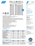
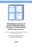
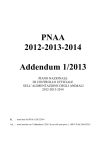
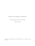
Hoshizaki
Hoshizaki America, Inc.
Commercial Series
Refrigerated Kitchen Equipment
Models
CR3B-FS
CR3B-HS
CF3B-FS
CF3B-HS
“A Superior Degree
of Reliability”
PARTS LIST
www.hoshizaki.com
Number: 71318
Issued: 3-4-2011
CONTENTS
Auxiliary Codes....................................................................................................................... 3
Note About Ordering Parts..................................................................................................... 3
A. Reach-In Assembly............................................................................................................. 4
B. Refrigeration Circuit............................................................................................................ 7
One Section: CR3B-FS, CR3B-HS..................................................................................... 7
Two Section: CR3B-FS, CR3B-HS..................................................................................... 9
One Section: CF3B-FS, CF3B-HS....................................................................................11
Two Section: CF3B-FS, CF3B-HS ................................................................................... 13
C. Control Box Assembly...................................................................................................... 15
One & Two Section: CR3B-FS, CR3B-HS........................................................................ 15
One Section: CF3B-FS, CF3B-HS................................................................................... 15
Two Section: CF3B-FS, CF3B-HS.................................................................................... 16
D. Door-Right Hinged............................................................................................................ 17
Full Solid: CR3B-FS, CF3B-FS......................................................................................... 17
Half Solid: CR3B-HS, CF3B-HS....................................................................................... 18
E. Door-Left Hinged.............................................................................................................. 20
Full Solid: CR3B-FS, CF3B-FS......................................................................................... 20
Half Solid: CR3B-HS, CF3B-HS....................................................................................... 21
F. Accessories & Packaging.................................................................................................. 23
2
Auxiliary Codes
CR3B-FS
A-5 February 2011
CF3B-FS
A-5 January 2011
CR3B-HS
A-5 March 2011
CF3B-HS
A-5TBD
Auxiliary Code Breakdown
The auxiliary code is the first two characters in the serial number. The first character
indicates the year. Years progress or regress in alphabetical order. The series runs from
"A" through "V" and the letters "I" and "O" are skipped. The second character indicates
significant part changes within a year. Base is "5" and this number advances for each
change.
Note About Ordering Parts
Most assemblies cannot be ordered as complete units; parts in the assemblies generally
must be ordered separately.
3
A. Reach-In Assembly
CR3B-FS, CR3B-HS, CF3B-FS, CF3B-HS
A-5
43
41
42
44
45
35
27
46
39
22
1 1a
35
38
25
23
18
24
15
12
26
9
7 36
11
17
1 1a
8
16
10
10
14a
4
3
13 13a
2 2a
14
47
19
19
6 6a
5 5a
40
47
49
21
48
20
37
29
32
31 33
28 31
29
34
Full Doors
34 30
Half Doors
For Doors, see Section "D" and "E"
4
30
For Float Switch, see Condensate
Water Pump in Section "B"
Title: A. Reach-In Assembly
Models: CR3B-FS, CR3B-HS, CF3B-FS, CF3B-HS
Index
No. Description
Reach-In Assembly
Order Assembly Parts Individually
1
1a
2
2a
3
4
5
5a
6
6a
7
8
9
10
11
12
13
13a
14
14a
15
16
17
18
19
20
21
22
23
24
25
26
27
28
29
30
Top-Rear Plate
Truss Head Screw
Base Plate
Hex Head Tapping Bolt
Caster Plate
Front Plate
4-Inch Locking Caster
Hex Head Tapping Bolt
4-Inch Non-Locking Caster
Hex Head Tapping Bolt
Nameplate Cover
Evaporator Fan Shroud: One
Section
Evaporator Fan Shroud: Two
Section
Fan Guard
Evaporator Fan Shroud Side
(R): Two Section
Evaporator Fan Shroud Side
(L): Two Section
Pilaster
Truss Head Screw
Rear Duct Panel
Duct Stand Off
Light Plate
Light Socket
Light Bulb
Warning Label
Vertical Mullion Face: Two
Section (includes heater)
Horizontal Mullion Face: One
Section (includes heater)
Horizontal Mullion Face: Two
Section (includes heater)
Front Panel
Display Module (includes
mounting clips)
Door Switch
Lock (includes 2 keys)
Commercial Label
Emblem
Drain Reservoir
Drain Fitting
Silicone Hose
Material or
Model Number
CR3B-FS
CR3B-HS
CF3B-FS
CF3B-HS
5×10, SS
1/4-20×3/4
1/4-20×3/4
1/4-20×3/4
5×10, SS
CR3B-HS
CF3B-HS
CR3B-HS
CF3B-HS
CR3B-FS
CR3B-HS
CF3B-FS
CF3B-HS
L=150
Required Number
Part Number
1A2148A01
1A2152A01
1A2150A01
1A2154A01
3A6405-01
7C32-0510
3A6403-01
4A5213-01
3A6402-01
3A6404-01
4A4275-01
4A5213-01
4A4275-02
4A5213-01
4A3727-01
3A6446G01
A-5
1
1
1
1
2
12
1
8
4
1
3
12
2
12
1
1
3A6212G01
1
4A4860-01
3A6629G01
4
1
3A6638G01
1
3A0145-22
7C32-0510
2A5205-01
4A4874-01
3A6530-01
4A4443-01
4A4444-01
4A2968-03
2A5906G01
12
36
3
18
3
3
3
3
1
3A5684G01
1
3A5910G01
2
2A6416-01
4A4862-01
1
2
3A1826-01
4A4924-01
3A5816-01
3
3
1
3A5816-02
1
4A0560-01
3A5565-01
4A2792-01
7730I3812
1
2
2
2
5
Title: A. Reach-In Assembly
Models: CR3B-FS, CR3B-HS, CF3B-FS, CF3B-HS
Index
No.
31
32
33
34
35
36
Description
Drain Boot
PVC Tubing: One Section
PVC Tubing: Two Section
Reservoir Cover
Ground Screw
Commercial Nameplate
37
38
Caution Label
Wiring Label: One Section
39
Wiring Label: Two Section
40
Wiring Label: Receptacle Box
41
42
43
44
45
Receptacle Box
Receptacle Cover
Receptacle
Receptacle Box Clamp
Power Cord
46
Power Cord
47
Vertical Mullion Thermal
Breaker: Two Section
48
Horizontal Mullion Thermal
Breaker: One Section
Horizontal Mullion Thermal
Breaker: Two Section
49
Material or
Model Number Part Number A-5
4A4938-01
2
L=650
7716I1438
1
L=860
7716I1438
1
3A5898-01
2
433304-02
2
CR3B-FS
1A2155-01
1
CR3B-HS
1A2155-03
1
CF3B-FS
1A2155-02
1
CF3B-HS
1A2155-04
1
4A1931-01
1
CR3B-FS
3A6581-01
1
CR3B-HS
CF3B-FS
3A6583-01
1
CF3B-HS
CR3B-FS
3A6582-01
1
CR3B-HS
CF3B-FS
3A6584-01
1
CF3B-HS
CR3B-FS
3A6623-01
1
CR3B-HS
CF3B-FS
3A6407-01
1
CF3B-HS
4A5314-01
1
4A5315-01
1
4A5316-01
2
4A5317-01
1
CR3B-FS
4A5379-01
1
CR3B-HS
CF3B-FS
4A5318-01
1
CF3B-HS
CR3B-FS
2A5908G01
1
CF3B-FS
CR3B-HS
2A5908G02
1
CF3B-HS
CR3B-HS
3A5931G01
1
CF3B-HS
CR3B-HS
3A5951G01
2
CF3B-HS
6
Required Number
B. Refrigeration Circuit
One Section: CR3B-FS, CR3B-HS
A-5
5
23
6
31
24
25 26
21 21a
22
27 28
17
18
20 20a 20b 20c
7
9 9a
8 8a
10
12
2
3
13
4
11
1
1a 1b 1c
30
19 19a
32
29
14
15 15a
16
7
Title: B. Refrigeration Circuit
Model: One Section: CR3B-FS, CR3B-HS
Index
No. Description
Refrigeration Circuit
Order Assembly Parts Individually
1
Compressor
1a
Rubber Grommet
1b
Compressor Clip
1c
Screw
2
Terminal Cover (includes clip)
3
Cord Relief
4
Start Relay
5
Start Capacitor
6
7
8
8a
9
9a
10
11
12
13
14
15
15a
16
17
18
19
19a
20
20a
20b
20c
21
21a
22
23
24
25
26
27
28
29
30
31
32
Condenser
Condenser Shroud
Condenser Fan Guard
Truss Head Screw
Condenser Fan Motor
Self-Locking Nut
Condenser Fan Blade
Condensate Pan
Condensate Coil Strap
Condensate Coil
Evaporator
Evaporator Bracket
Screw
Evaporator Drain Bracket
Defrost Thermistor
Thermistor Clip
Evaporator Mount Bracket
Screw
Evaporator Fan
Flat Washer
Split Lock Washer
Tapping Screw
Evaporator Fan Bracket
Screw
Drier
High-Pressure Switch
Expansion Valve
Expansion Valve Cover (A)
Expansion Valve Cover (B)
Expansion Valve Bulb Holder
Clamp
Condensate Water Pump
(includes float switch)
PVC Tubing
R134a Label
Cabinet Thermistor
Material or
Model Number Part Number A-5
1A2160A01
1
280MFD,
125/165 VAC
5×12, SS
8-32
L=350
4A3177-01
4A1452-01
4A4867-01
4A4993-01
4A2141-01
4A2152-01
4A2135-03
4A2134-01
1
4
4
4
1
2
1
1
2A6415-01
3A6631G01
2A5187-01
7C32-0512
4A4869-01
7N21I0832
3A5817-01
2A5218-01
3A5672-01
3A6465G01
2A6463-01
3A5492-01
4A4993-02
3A5495-01
4A4865-02
4A3248G01
3A5493-01
4A4993-02
4A5343-01
7W22-0500
7L22-0500
4A3883-01
2A6424-01
4A4993-02
4A1113-01
4A2516-01
4A4597-01
3A0372-01
3A0372-02
3A0107-01
443461-01
3A6339G01
1
1
1
4
1
4
1
1
1
1
1
1
2
1
1
1
2
4
2
8
8
8
1
5
1
1
1
1
1
1
1
1
7716I1438
444463-01
4A4864-01
1
1
1
8
Required Number
B. Refrigeration Circuit
Two Section: CR3B-FS, CR3B-HS
A-5
1 1a 1b 1c
3
4
2
5
31
33 34
32
29
30
26 26a
27
7
8
27a 27b 27c
11
28
15 15a
17
14
13
16 16a
20
19
18
10
9
12
6 6a
21
23
25
24
9
22 22a
Title: B. Refrigeration Circuit
Model: Two Section: CR3B-FS, CR3B-HS
Index
No. Description
Refrigeration Circuit
Order Assembly Parts Individually
1
Compressor
1a
Screw
1b
Rubber Grommet
1c
Compressor Clip
2
Start Relay
3
Start Capacitor
4
Terminal Cover (includes clip)
5
Cord Relief
6
Evaporator Mount Bracket
6a
Screw
7
Expansion Valve Bulb Holder
8
Clamp
9
Condensate Water Pump
(includes float switch)
10
PVC Tubing
11
R134a Label
12
Cabinet Thermistor
13
Condenser
14
Condenser Shroud
15
Condenser Fan Guard
15a Truss Head Screw
16
Condenser Fan Motor
16a Self-Locking Nut
17
Condenser Fan Blade
18
Condensate Pan
19
Condensate Coil
20
Condensate Coil Strap
21
Evaporator
22
Evaporator Bracket
22a Screw
23
Evaporator Drain Bracket
24
Defrost Thermistor
25
Thermistor Clip
26
Evaporator Fan Bracket
26a Screw
27
Evaporator Fan
27a Flat Washer
27b Split Lock Washer
27c Tapping Screw
28
Evaporator Shroud
29
Ground Screw
30
Drier
31
High-Pressure Switch
32
Expansion Valve
33
Expansion Valve Cover (A)
34
Expansion Valve Cover (B)
Material or
Model Number Part Number A-5
1A2161A01
1
L=350
5×12, SS
8-32
M5, SS
M5, SS
4A3958-01
4A4993-01
4A1452-01
4A4867-01
4A2135-04
4A2134-01
4A2141-01
4A2152-01
3A5493-01
4A4993-02
3A0107-01
443461-01
3A6339G01
1
4
4
4
1
1
1
2
2
4
1
1
1
7716I1438
444463-01
4A4864-01
2A5862-01
3A6630G01
2A5187-01
7C32-0512
4A4869-01
7N21I0832
3A5817-01
2A5218-02
3A5598-02
3A5672-01
2A6464-01
3A5492-01
4A4993-02
3A5903-01
4A4865-01
4A3248G01
2A6173-01
4A4993-02
4A5343-01
7W22-0500
7L22-0500
4A3883-01
3A5902-01
433304-02
4A1113-01
4A2516-01
4A4598-01
3A0372-01
3A0372-02
1
1
1
1
1
1
4
1
4
1
1
1
1
1
2
2
1
1
1
1
6
3
12
12
12
1
1
1
1
1
1
1
10
Required Number
B. Refrigeration Circuit
One Section: CF3B-FS, CF3B-HS
A-5
32
34
7
24
6
25
26 27
17
23
22 22a
28 29
9 9a
21 21a 21b 21c
8 8a
10
12
13
11
5
31
1a 1b 1c
1
30
2
3
4
33
20 20a
15 15a
14 16
19
11
18
Title: B. Refrigeration Circuit
Model: One Section: CF3B-FS, CF3B-HS
Index
No. Description
Refrigeration Circuit
Order Assembly Parts Individually
1
Compressor
1a
Rubber Grommet
1b
Compressor Clip
1c
Screw
2
Terminal Cover (includes clip)
3
Cord Relief
4
Start Relay
5
Start Capacitor
6
7
8
8a
9
9a
10
11
12
13
14
15
15a
16
17
18
19
20
20a
21
21a
21b
21c
22
22a
23
24
25
26
27
28
29
30
31
32
33
34
Condenser
Condenser Shroud
Condenser Fan Guard
Truss Head Screw
Condenser Fan Motor
Self-Locking Nut
Condenser Fan Blade
Condensate Pan
Condensate Coil Strap
Condensate Coil
Evaporator
Evaporator Bracket
Screw
Evaporator Drain Bracket
Defrost Thermistor
Defrost Heater
Defrost Thermostat
Evaporator Mount Bracket
Screw
Evaporator Fan
Flat Washer
Split Lock Washer
Tapping Screw
Evaporator Fan Bracket
Screw
Drier
High-Pressure Switch
Expansion Valve
Expansion Valve Cover (A)
Expansion Valve Cover (B)
Expansion Valve Bulb Holder
Clamp
Condensate Water Pump
(includes Float Switch)
PVC Tubing
R404A Label
Cabinet Thermistor
Condenser Block
Material or
Model Number Part Number A-5
1A2157A01
1
240MFD,
125/165VAC
5×12, SS
8-32
L=350
4A3808-01
4A1452-01
4A4867-01
4A4993-01
4A3112-01
4A1454-01
4A3113-01
4A2134-03
1
4
4
4
1
2
1
1
2A6415-01
3A6631G01
2A5187-01
7C32-0512
4A4869-01
7N21I0832
3A5817-01
2A5218-01
3A5672-01
3A6465G01
2A6463-01
3A5492-01
4A4993-02
3A5495-01
4A4865-01
2A5378-01
4A0954-02
3A5493-01
4A4993-02
4A5343-01
7W22-0500
7L22-0500
4A3883-01
2A6424-01
4A4993-02
4A1113-01
4A2516-02
4A5344-01
3A0372-01
3A0372-02
3A0107-01
443461-01
3A6339G01
1
1
1
4
1
4
1
1
1
1
1
1
2
1
1
1
1
2
4
2
8
8
8
1
5
1
1
1
1
1
1
1
1
7716I1438
4A0960-01
4A4864-01
3A6579-01
1
1
1
1
12
Required Number
B. Refrigeration Circuit
Two Section: CF3B-FS, CF3B-HS
A-5
31
32
23
33 34
29
30
26 26a
6
27
27a 27b 27c
28
10
16
14 14a
13
1a 1b 1c
1
7
12
15 15a
19
18
2
3
9
4
8
5
17
5a
11
20
22
21 21a
25
24
13
Title: B. Refrigeration Circuit
Model: Two Section: CF3B-FS, CF3B-HS
Index
No. Description
Refrigeration Circuit
Order Assembly Parts Individually
1
Compressor (includes items 2
through 4)
1a
Screw
1b
Rubber Grommet
1c
Compressor Clip
2
Terminal Cover (includes clip)
3
Protector
4
Protector Holder
5
Evaporator Mount Bracket
5a
Screw
6
Expansion Valve Bulb Holder
7
Clamp
8
Condensate Water Pump
(includes float switch)
9
PVC Tubing
10
R404A Label
11
Cabinet Thermistor
12
Condenser
13
Condenser Shroud
14
Condenser Fan Guard
14a Truss Head Screw
15
Condenser Fan Motor
15a Self-Locking Nut
16
Condenser Fan Blade
17
Condensate Pan
18
Condensate Coil
19
Condensate Coil Strap
20
Evaporator
21
Evaporator Bracket
21a Screw
22
Evaporator Drain Bracket
23
Defrost Thermistor
24
Defrost Heater
25
Defrost Thermostat
26
Evaporator Fan Bracket
26a Screw
27
Evaporator Fan
27a Flat Washer
27b Split Lock Washer
27c Tapping Screw
28
Evaporator Shroud
29
Ground Screw
30
Drier
31
High-Pressure Switch
32
Expansion Valve
33
Expansion Valve Cover (A)
34
Expansion Valve Cover (B)
Material or
Model Number Part Number A-5
1A2019A01
1
L=350
5×12, SS
8-32
M5, SS
M5, SS
4A3815-01
1
4A4993-01
4A1452-01
4A4867-01
4A2141-01
4A3679-01
4A3680-01
3A5493-01
4A4993-02
3A0107-01
443461-01
3A6339G01
4
4
4
1
1
1
2
4
1
1
1
7716I1438
4A0960-01
4A4864-01
2A5902-01
3A6630G01
2A5187-01
7C32-0512
4A4869-01
7N21I0832
3A5817-01
2A5218-02
3A6025-01
3A5672-01
2A6464-01
3A5492-01
4A4993-02
3A5903-01
4A4865-01
2A5991-01
4A0954-02
2A6173-01
4A4993-02
4A5343-01
7W22-0500
7L22-0500
4A3883-01
3A5902-01
433304-02
4A0924-01
4A2516-02
4A5161-01
3A0372-01
3A0372-02
1
1
1
1
1
1
4
1
4
1
1
1
1
1
2
2
1
1
1
1
1
6
3
12
12
12
1
1
1
1
1
1
1
14
Required Number
C. Control Box Assembly
One & Two Section: CR3B-FS, CR3B-HS
One Section: CF3B-FS, CF3B-HS
A-5
4
2
6
5
7
1
3
10
8
9
Title: C. Control Box Assembly Model: One & Two Section: CR3B-FS, CR3B-HS; One Section: CF3B-FS, CF3B-HS
Required Number
Index
Material or
No. Description
Model Number Part Number A-5
Control Box Assembly
CR3B-FS
2A6115A01
2
Order Assembly Parts Individually CR3B-HS
CF3B-FS
2A5346A01
1
CF3B-HS
1
Toggle Switch
4A0424-01
1
2
Door Switch Relay
120VAC
406132-07
1
3
Terminal Block
4A2619-01
1
4
Control Module
CR3B-FS
4A4861-03
1
CR3B-HS
CF3B-FS
4A5101-03
1
CF3B-HS
5
Display Cable
4A4863-01
1
6
Power Cord
4A0520-01
1
7
Ground Screw
433304-02
2
8
Control Box Cover
2A5209-01
1
9
Power Switch Label
4A2196-01
1
10
Compressor Relay
120VAC
4A1307-01
1
15
C. Control Box Assembly
Two Section: CF3B-FS, CF3B-HS
A-5
7
2
5
4
3
11
1
6
10
8
9
12
13
Title: C. Control Box Assembly
Model: Two Section: CF3B-FS, CF3B-HS
Index
No. Description
Control Box Assembly
Order Assembly Parts Individually
1
Toggle Switch
2
Control Module
3
Display Cable
4
Power Cord
5
Door Switch Relay
6
Terminal Block
7
Compressor Relay
8
Start Relay
9
Run Capacitor
10
Start Capacitor
11
Ground Screw
12
Control Box Cover
13
Power Switch Label
Material or
Model Number Part Number A-5
2A6195A01
1
4A0424-01
4A5101-03
4A4863-01
4A0520-01
406132-07
4A2619-01
4A1307-01
4A3683-01
4A4208-01
4A2134-02
433304-02
2A6176-01
4A2196-01
16
1
1
1
1
1
1
1
1
1
1
2
1
1
Required Number
D. Door-Right Hinged
Full Solid: CR3B-FS, CF3B-FS
A-5
6
5
4
9 9a
3 3a
7
8
10
6
11
1 1a
2
Title: D. Door-Right Hinged
Model: Full Solid: CR3B-FS, CF3B-FS
Index
No. Description
Door-Right Hinged; Full Solid
Order Assembly Parts Individually
1
Hinge Bracket (R)
1a
Countersunk Screw
2
Thrust Washer
3
Hinge Bracket
3a
Countersunk Screw
4
Lock Washer
5
Screw
6
Truss Head Screw (filler screws)
7
Door Assembly (R)
(includes items 8 through 11)
8
Door Gasket
9
Hinge Cartridge
9a
Countersunk Screw
10
Truss Head Screw (filler screws)
11
Bearing
Material or
Model Number Part Number A-5
2A6257A01
2
5×20, SS
5×20, SS
5×10, SS
5×20, SS
5×10, SS
3A6250G01
7C42-0520
4A5234-01
3A6249-01
7C42-0520
4A5231-01
4A5230-01
7C32-0510
2A6258G01
1
3
1
1
3
1
1
8
1
2A5192-01
3A6258-01
7C42-0520
7C32-0510
4A5232-01
1
1
2
2
1
17
Required Number
D. Door-Right Hinged
Half Solid: CR3B-HS, CF3B-HS
A-5
3
4
1 1a
13
8
11a
11
9
10
7 7a
8
18
6
5a
12
17
5
15
14
8
16
16a
3
2
1 1a
4
18
Title: D. Door-Right Hinged Model: Half Solid: CR3B-HS, CF3B-HS
Index
No. Description
Door-Right Hinged; Half Solid
Order Assembly Parts Individually
1
Hinge Bracket
1a
Countersunk Screw
2
Thust Washer
3
Lock Washer
4
Screw
5
Hinge Bracket (R)
5a
Countersunk Screw
6
Thrust Washer
7
Half Door Lock
7a
Bolt
8
Truss Head Screw (filler screws)
9
Door Assembly (UR, LL)
(includes items 10 through 13)
10
Truss Head Screw (filler screws)
11
Hinge Cartrige
11a Countersunk Screw
12
Bearing
13
Door Gasket
14
Door Assembly (LR, UL)
(includes items 15 through 18)
15
Truss Head Screw (filler screws)
16
Hinge Cartrige
16a Countersunk Screw
17
Bearing
18
Door Gasket
Material or
Model Number Part Number A-5
2A6251A01
2
5×20, SS
5×20, SS
5×16, SS
5×10, SS
5×10, SS
5×20, SS
5×10, SS
5×20, SS
3A6249-01
7C42-0520
4A5233-01
4A5231-01
4A5230-01
3A6250G01
7C42-0520
4A5234-01
4A5249-01
449879-08
7C32-0510
2A6252G01
2
6
2
2
2
1
2
1
1
1
11
1
7C32-0510
3A6258-01
7C42-0520
4A5232-01
2A5192-02
2A6253G01
2
1
2
1
1
1
7C32-0510
3A6258-01
7C42-0520
4A5232-01
2A5192-02
2
1
2
1
1
19
Required Number
E. Door-Left Hinged
Full Solid: CR3B-FS, CF3B-FS
A-5
3 3a
5
4
8
6
9 9a
7
11
2
10
6
1 1a
Title: E. Door-Left Hinged
Model: Full Solid: CR3B-FS, CF3B-FS
Index
No. Description
Door-Left Hinged; Full Solid
Order Assembly Parts Individually
1
Hinge Bracket (L)
1a Countersunk Screw
2
Thrust Washer
3
Hinge Bracket
3a Countersunk Screw
4
Lock Washer
5
Screw
6
Truss Head Screw (filler screws)
7
Door Assembly (L)
(includes items 8 through 11)
8
Door Gasket
9
Hinge Cartridge
9a Countersunk Screw
10 Truss Head Screw (filler screws)
11
Bearing
Material or
Model Number Part Number A-5
2A6263A01
1
5×20, SS
5×20, SS
5×10, SS
5×20, SS
5×10, SS
3A6250G02
7C42-0520
4A5234-01
3A6249-01
7C42-0520
4A5231-01
4A5230-01
7C32-0510
2A6264G01
1
3
1
1
3
1
1
8
1
2A5192-01
3A6258-01
7C42-0520
7C32-0510
4A5232-01
1
1
2
2
1
20
Required Number
E. Door-Left Hinged
Half Solid: CR3B-HS, CF3B-HS
A-5
4
3
1 1a
18
16a
16
8
14
17
6
15
5 5a
12
10
7
13
7a
8
9
11
2
3
4
8
11a
1 1a
21
Title: E. Door-Left Hinged Model: Half Solid: CR3B-HS, CF3B-HS
Index
No. Description
Door-Left Hinged; Half Solid
Order Assembly Parts Individually
1
Hinge Bracket
1a Countersunk Screw
2
Thrust Washer
3
Lock Washer
4
Screw
5
Hinge Bracket (L)
5a Countersunk Screw
6
Thrust Washer
7
Half Door Lock
7a Bolt
8
Truss Head Screw (filler screws)
9
Door Assembly (UR, LL)
(includes items 10 through 13)
10 Truss Head Screw (filler screws)
11
Hinge Cartridge
11a Countersunk Screw
12 Bearing
13 Door Gasket
14 Door Assembly (LR, UL)
(includes items 15 through 18)
15 Truss Head Screw (filler screws)
16 Hinge Cartridge
16a Countersunk Screw
17 Bearing
18 Door Gasket
Material or
Model Number Part Number A-5
2A6256A01
1
5×20, SS
5×20, SS
5×16, SS
5×10, SS
5×10, SS
5×20, SS
5×10, SS
5×20, SS
3A6249-01
7C42-0520
4A5233-01
4A5231-01
4A5230-01
3A6250G02
7C42-0520
4A5234-01
4A5249-01
449879-08
7C32-0510
2A6252G01
2
6
2
2
2
1
2
1
1
1
11
1
7C32-0510
3A6258-01
7C42-0520
4A5232-01
2A5192-02
2A6253G01
2
1
2
1
1
1
7C32-0510
3A6258-01
7C42-0520
4A5232-01
2A5192-02
2
1
2
1
1
22
Required Number
F. Accessories & Packaging
CR3B-FS, CR3B-HS, CF3B-FS, CF3B-HS
A-5
3
2
4
6
7
5
Title: F. Accessories & Packaging
Model: CR3B-FS, CR3B-HS, CF3B-FS, CF3B-HS
Index
No. Description
1
Instruction Manual
2
Shelf Kit: One Section (3 Pack)
(includes items 3 and 4)
3
Shelf
4
Shelf Clip
5
Shelf Kit: Two Section (3 Pack)
(one kit includes half of items 6
and 7)
6
Shelf
7
Shelf Clip
Packaging
Material or
Model Number Part Number
91A3KN10A
HS-3508
3A1416A03
HS-3717
CR3B-FS
CR3B-HS
CF3B-FS
CF3B-HS
Required Number
A-5
1
1
3A1387-01
428957-01
3A6110A01
3
12
2
3A2830-05
428957-01
6
24
1A2147A01
1A2151A01
1A2149A01
1A2153A01
23