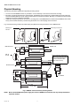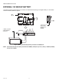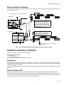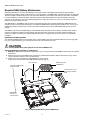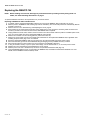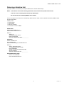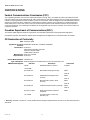
1
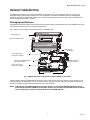
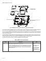
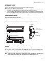
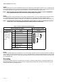
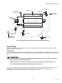
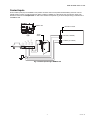
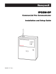
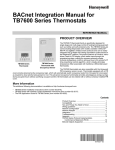
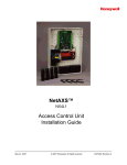
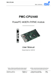
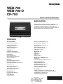
WEB-700
WEB-700-O
CP-700
INSTALLATION INSTRUCTIONS
APPLICATION
The WEB-700 and CP-700 are compact, embedded
controller/server platforms that allow integrated control and
management of external devices over the Internet. They
provide suppport for two optional communications boards as
well as optional remote I/O expansion modules.
CONTENTS
About This Guide 2
Related Documentation 2
External 12V Backup Battery 18
Wiring to Remote I/O Modules 19
Product Description 3
Packaging and Features 3
Technical Specifications 5
Equipment Ratings 5
Power Up and Initial Checkout 19
Apply Power 19
Check the Status LED 19
About the Backup Batteries 20
NiMH battery pack 20
Preparation 6
Included in this Package 6
Material and Tools Required 6
Precautions 6
Safety Precautions 6
Static Discharge Precautions 7
Battery Precautions 7
Mounting 7
Environmental Requirements 7
Physical Mounting 8
Removing and Replacing the Cover 9
Board Layout 10
About Expansion Options 11
About Option Cards 11
About Remote I/O Modules 12
About MiniPCI Cards 12
Wiring Details 13
Communications Wiring 13
Grounding 14
Power Wiring 15
Contact Inputs 17
About LEDs 21
Status 21
Heartbeat 21
Debug 21
Ethernet Ports 21
Maintaining the WEB/CP-700 21
Cleaning 21
Required NiMH Battery Maintenance 22
Replacement Parts 23
Non-replaceable Parts 23
Standard Replacement Parts 23
New Replacement Unit 23
Replacing the WEB/CP-700 24
Returning a Defective Unit 27
Certifications 26
Federal Communications Commission (FCC) 26
Canadian Department of Communications (DOC) 26
CE Declaration of Conformity 26
Tab Mounting Dimensions 27
CE AND OTHER LOGOS
Put Bar Code Here
95-7776-03
WEB-700 WEB-700-O CP-700
ABOUT THIS GUIDE
This document covers the mounting and wiring of the Tridium® WEB/CP-700 (T-700) controller. It assumes that you are an
engineer, technician, or service person who is performing control system installation. Instructions in this document apply to the
following products:
Model
Description
WEB-700
WEB-700-O
CP-700
DIN mount 7 series controller, powered by separate plug-in power supply module or wall mount AC
power adapter. Controller supports optional remote I/O expansion modules and internal
communications option cards.
NPB-PWR-UN-H
90–263Vac universal input/15Vdc output power supply module, DIN mountable.
NPB-WPM-US
Wall-mount, 120V AC power adapter.
NOTE: Not covered in this document is the NiagaraAX software installation and configuration required for a fully functioning unit. Refer to the Niagara AX Install and Startup Guide for this information.
In addition, the mounting and wiring of controller expansion options are covered in separate documents. See
the section About Expansion Options, page 11.
Related Documentation
For more information on configuring and using the WEB/CP-700 controller, consult the following documents:
•
•
•
•
•
•
•
•
•
•
IO-16-REM-H Installation and Configuration Instructions, Form # 95-7768
NPB-LON Option Installation Sheet, Form # 62-0263
NPB-MDM Option Installation Sheet, Form # 95-7730
NPB-GPRS-W-H Installation Sheet, Form # 62-0301
NPB-SRAM (Static RAM) Option Installation Instructions, Form #62-0425
NPB-ZWAVE Option Card Installation Instructions, Form # 62-0349
NPB-WIFI-7 Controller WIFI Option Installation Instructions, Form # 62-0426
Niagara AX Install and Startup Guide
NiagaraAX Nrio Guide
NiagaraAX User Guide
95-7776—03
2
WEB-700 WEB-700-O CP-700
PRODUCT DESCRIPTION
The WEB/CP-700 controller is a compact embedded processor platform using on-board Flash memory for backup, in an
expandable DIN-modular package. Designed for use in commercial environments, the WEB/CP-700 runs the NiagaraAX
Framework to provide integrated control, supervision, and network management solutions for wide variety of networked field
devices. NiagaraAX-3.5 or later is required.
Packaging and Features
The WEB/CP-700 features a DIN-mount controller base with mounting tabs for alternate panel mount. Two available comm option
card slots are accessed under the controller’s removable cover.
Fig. 1 and Fig. 2 show locations of important features of the WEB/CP-700.
Removable cover
Status and heartbeat LEDs
NiMH backup
battery pack
Option card #2 area
(card shown installed)
Connector for NPB-PWR-UN-H
power supply module
RS-485, 15V Power
Output Connector
Option card #1 area
(card shown installed)
Connector ports
Fig. 1. WEB/CP-700 Cover removed with 2 options installed on main board.
Typical installation requires an NPB-PWR-UN-H universal power supply module (furnishing 15Vdc) for power, attaching to the
controller’s left side. An RS-485 port is on the controller’s opposite right end connector, along with 15Vdc power for support of
remote I/O expansion modules, either chained directly and/or wired remotely.
NOTE: Instead of using the NPB-PWR-UN-H power supply module, you can adapt an NPB-WPM-US wall mount AC
power adapter to power the WEB/CP-700 controller. However, you cannot directly attach I/O expansion modules
in this configuration, nor power remote I/O modules from that NPB-WPM-US.
3
95-7776—03
WEB-700 WEB-700-O CP-700
.
NiMH battery pack
and shield removed
Removed
option cards
Main controller board
DIN-mount base with screw tabs
for panel mount
Connector ports
Fig. 2. WEB/CP-700 main controller board and 2 option cards uninstalled.
As a 7 series controller, the WEB/CP-700 uses a PowerPC 440EPx processor, 1GB Flash storage, and 1 GB DDR-2 RAM. TCP/
IP access is via two standard Gigabit Ethernet ports. Serial communications ports (RS-232, RS-485) are standard.
One or two option cards can be added for additional communications, e.g. LonWorks FTT-10, or another RS-232 port. A MiniPCI
slot is also available for WiFi 802.11g support. The WEB/CP-700 uses the QNX Neutrino operating system, with the Oracle Java
Hotspot VM (Virtual Machine).
Two status LEDs are visible atop the cover. Integral contact inputs are provided to allow system monitoring of UPS power and
battery, and an external enclosure door. A rechargeable NiMH battery pack is included inside the unit, and a separate connector
provides recharging and monitoring of an external 12V sealed lead-acid battery ordered separately.
The table below provides a summary of features of the WEB/CP-700 controller model.
Table 1. WEB/CP-700 features and options
Model
WEB-700-O
CP-700
Description
DIN-mountable controller. PowerPC 440Epx 667MHz processor, 1GB NAND
Flash storage, 1 GB base DDR-2 system RAM.
Two 1GB Ethernet,
RJ-45
Includes integral NiMH battery pack, two open enhanced comm option card
slots, one open MiniPCI slot (for WiFi 802.11g option card). Not furnished is
NPB-PWR-UN-H universal power supply, or external 12V sealed lead-acid
battery and harness.
One RS-232 Serial,
DB-9 male
.
95-7776—03
Ports
4
One RS-485 Serial,
isolated, with 15V/
12Vdc power, 6position plug on right
side.
WEB-700 WEB-700-O CP-700
Technical Specifications
WEB/CP-700 PLATFORM
• PowerPC 440Epx @ 667MHz processor (speed approximate due to spread spectrum clock).
• 1GB on-board NAND Flash storage.
• 1 GB DDR-2 333Mhz RAM (maximum Java Heap size 384MB).
• Two (2) Gigabit Ethernet ports.
• Standard RS-232 port.
• 6-position end connector with isolated RS-485/15Vdc power (usable as a standard non-powered isolated RS-485 port, or to
support remote I/O modules).
• MiniPCI option slot, for optional NPB-WIFI-7 802.11 b/g WIFI adapter (WEBsAX-3.6 required).
• Two (2) available comm option slots in the WEB/CP-700, for LonWorks, RS-485 or RS-232, GPRS/Edge Cellular, Jennic
802.15.4 wireless, etc.
• LEDs on front of unit to monitor power and system status.
• Available contact inputs (3) to monitor external UPS AC present, UPS battery level, external enclosure door status.
POWER SUPPLY
• Requires universal AC input (90V – 264V) NPB-PWR-UN-H power supply module, supplies 15Vdc, 30VA. Alternately, a
NPB-WPM-US wall-mount AC adapter can power the WEB/CP-700 only (requires removal of barrel plug end and wiring to end
connector).
• Includes integral rechargeable NiMH backup battery pack, for short duration AC power fail operation.
• Connection for external, rechargeable, 12V sealed lead-acid battery, for continuous system operation over longer power
outages. Provides trickle charge and monitoring support to separately ordered batteries.
OPERATING SYSTEM
• QNX Neutrino Real-Time Operating System.
• Oracle Hotspot JVM (Java Virtual Machine) in units with WEBsAX-3.6 or later; IBM J9 JVM is used in units with WEBsAX-3.5.
• NiagaraAX software (WEBsAX-3.5 or later required). WEBsAX-3.6 or later required to use the optional NPB-WIFI-7 adapter.
PHYSICAL
• Plastic DIN-mount backplate with screw tabs for alternate panel mounting.
• Removable snap-on plastic cover with status LEDs and connecting cable.
• Cooling by internal air convection.
• Dimensions: 8.7" (221mm) wide x 5.6" (142mm) high x 2.44" (62mm) deep.
• Weight: Net 1.67 lbs. (0.76 kg), Gross 2.0 lbs. (0.91 kg).
ENVIRONMENT
• Operating temperature range: 32°F to 122°F (0°C to 50°C).
• Relative humidity range: 10% to 90% at 77°F (25°C), non-condensing.
• Mechanical ambient conditions are as follows:
— Vibration, in operation: 5 to 9 Hz: 3.5mm amplitude, 9 to 150Hz: 1g.
— Shock resistance, in operation: 15g acceleration, 11 ms duration.
• Storage temperature range: 32°F to 158°F (0°C to 70°C).
• Storage relative humidity range: 5% to 94%, non-condensing.
Equipment Ratings
ELECTRICAL
• Input voltage range: 15Vdc (from separate AC power supply, 90Vac to 264Vac, 50/60Hz).
• Power consumption: 20VA maximum.
5
95-7776—03
WEB-700 WEB-700-O CP-700
PREPARATION
Unpack the WEB/CP-700 and inspect the package contents for damaged or missing components. If damaged, notify the
appropriate carrier at once and return any damaged components for immediate repair or replacement. See “Returning a
Defective Unit” on page 25.
• Included in this Package
• Material and Tools Required
Included in this Package
Included in this package you should find the following items:
• WEB/CP-700 controller.
• WEB/CP-700 Installation Instructions, Form Number 95-7776.
• Hardware bag containing the following items:
— Two (2) 6-position screw terminal plugs, one for integral contact inputs (door tamper, UPS battery OK, UPS AC present),
one end-mount to wire RS-485/power to optional remote expansion devices.
— One (1) 2-position screw terminal plug for external sealed lead-acid (SLA) rechargeable battery (not provided).
— One (1) grounding wire, with quick-disconnect 0.187" female connector.
Material and Tools Required
The following supplies and tools are typically required for installation:
• NPB-PWR-UN-H universal AC power supply module, 90-263 Vac input, 15Vdc 30W output, DIN-mount capable, with
grounding wire.
Alternatively, a NPB-WPM-US wall-mount AC adapter can power the WEB/CP-700 controller only. You must cut off the
adapter’s barrel plug end, and then wire leads into the controller’s end connector. A multimeter is needed to check polarity.
• DIN rail, type NS35/7.5 (35mm x 7.5mm) and DIN rail end-clips (stop clips), unless using panel mounting method with screws
through mounting tabs.
• Suitable tools and fasteners for mounting unit and accessories.
• #2 phillips screwdriver: used to install and remove an optional option card.
• Small flat-blade screwdriver: used for making wiring connections to removable screw terminal plugs.
• (Optional) One or two 12V sealed-lead-acid (SLA) rechargeable backup batteries, with wire harness for connecting to the
2-position connector on the unit. Should be sized as required by the system. See Contact Input wiring to WEB/CP-700, page
17.
PRECAUTIONS
This document uses the following warning and caution conventions:
CAUTION
Cautions remind the reader to be careful. They alert readers to situations where there is a chance that the reader
might perform an action that cannot be undone, might receive unexpected results, or might lose data. Cautions
contain an explanation of why the action is potentially problematic.
WARNING
Warnings alert the reader to proceed with extreme care in situations where there is a chance that the reader
might do something that can result in personal injury or equipment damage. Warnings contain an explanation of
why the action is potentially dangerous.
Safety Precautions
The following items are warnings of a general nature relating to the installation and start-up of the WEB/CP-700 controller. Be
sure to heed these warnings to prevent personal injury or equipment damage.
95-7776—03
6
WEB-700 WEB-700-O CP-700
WARNING
A 120Vac or 240Vac circuit powers the NPB-PWR-UN-H power supply for the controller. 15Vdc input (DC only) to
controller.
Disconnect power before installation or servicing to prevent electrical shock or equipment damage.
Make all connections in accordance with national and local electrical codes. Use copper conductors only.
To reduce the risk of fire or electrical shock, install in a controlled environment relatively free of contaminants.
This device is only intended for use as a monitoring and control device. To prevent data loss or equipment
damage, do not use it for any other purpose.
Static Discharge Precautions
Static charges produce voltages high enough to damage electronic components. The microprocessors and associated circuitry
within a WEB/CP-700 controller are sensitive to static discharge. Follow these precautions when installing, servicing, or operating
the system:
CAUTION
Work in a static-free area.
Discharge any static electricity you may have accumulated. Discharge static electricity by touching a known,
securely grounded object. Do not handle printed circuit boards (PCBs) without proper protection against static
discharge. Use a wrist strap when handling PCBs. The wrist strap clamp must be secured to earth ground.
Battery Precautions
CAUTION
The NiMH battery used in this device may present a risk of fire or chemical burn if mistreated. Do not
disassemble, heat above 122ºF (50ºC), or incinerate. Replace battery pack with NPB-BATT-7 only. Use of another
battery may present a risk of fire or explosion.
Dispose of used battery promptly. Keep away from children. Do not disassemble and do not dispose of in fire.
Replace external backup battery with Listed Power Source Battery Only.
MOUNTING
NOTE: This product is intended for indoor use only. The unit should not be exposed to ambient conditions outside of
the range of 32ºF (0ºC) to 122ºF (50ºC), or relative humidity outside the range of 10 to 90% at 77ºF (25ºC), noncondensing. Refer to Environment, page 5 for further details on mechanical and storage specifications.
Before mounting the unit, install any option card(s) and memory upgrade. See About Expansion Options, page
11.
Environmental Requirements
Note the following requirements for the WEB/CP-700 mounting location:
• If mounting inside an enclosure, that enclosure should be designed to keep the unit within its required operating range
considering a 20-watt dissipation by the controller, plus dissipation from any other devices installed in the same enclosure.
This is especially important if the controller is mounted inside an enclosure with other heat producing equipment.
• Do not mount the unit:
— in an area with excessive moisture, corrosive fumes, or explosive vapors.
— where vibration or shock is likely to occur.
— in a location subject to electrical noise. This includes the proximity of large electrical contractors, electrical machinery,
welding equipment, spark igniters, and variable frequency drives.
7
95-7776—03
WEB-700 WEB-700-O CP-700
Physical Mounting
The following information applies about physically mounting the unit.
• You can mount the WEB/CP-700 in any orientation. It it not necessary to remove the cover before mounting.
• Mounting on a 35mm wide DIN rail is recommended. The WEB/CP-700 unit base has a molded DIN rail slot and locking clip,
as does the NPB-PWR-UN-H power supply module and any I/O expansion modules. Mounting on a DIN rail ensures accurate
alignment of connectors between all modules.
• If DIN rail mounting is impractical, use screws in mounting tabs on the NPB-PWR-UN-H module and the WEB/CP-700, as well
as any end-connected accessory. Tab mounting dimensions are on the last page of this document.
Fig. 3 and the following procedure provides step-by-step DIN rail mounting instructions for the WEB/CP-700.
Mounting on
DIN rail
Removing from DIN rail
WEB/CP-700
NPB-PWR-UN-H
DIN rail
end clip
Secure controller or last directly
attached I/O module using either
screws or DIN rail end clip (if end
clip does not interfere with 6position end connector).
NPB-PWR-UN-H
5.6"
(142)
IO-16-REM-H
4.1" (104)
3.46"
(88)
11.75" (298)
15.125" (384)
Fig. 3. WEB/CP-700 and accessory mounting details.
NOTE: Mount the NPB-PWR-UN-H power supply first, then the WEB/CP-700 controller, then any directly attached I/O
expansion module.
95-7776—03
8
WEB-700 WEB-700-O CP-700
To mount on DIN rail
1. Securely install the DIN rail with at least two screws, near the two rail ends.
2. Position the NPB-PWR-UN-H power supply module on the rail, tilting to hook DIN rail tabs over one edge of the DIN rail
(Fig. 3).
3. Use a screwdriver to pry down the plastic locking clip, and push down and in on the module, to force the locking clip to snap
over the other edge of the DIN rail.
4. Mount the WEB/CP-700 controller onto the DIN rail in the same way, such that its left 6-position end connector faces the
NPB-PWR-UN-H power supply.
5. Slide the two devices together along the DIN rail to connect their 6-position connectors.
6. If installing any I/O expansion modules, repeat this for each one, until all are mounted on the DIN rail and firmly connected
into one assembly.
7. To keep the final assembly together, secure at both ends with DIN rail end-clips provided by the DIN rail vendor. This also
prevents the assembly from sliding on the DIN rail. See Fig. 3.
Removing and Replacing the Cover
You must remove the WEB/CP-700 cover to connect the battery (new unit), and/or to replace the NiMH battery, install any option
cards, or replace the NiMH battery. The cover snaps onto the base with four plastic end tabs–two on each end.
CAUTION
An LED ribbon cable connects the cover to the main board. Be careful when lifting the cover off. If the controller
is on a flat work surface, you can leave the cable connected, with the cover next to the unit. See Fig. 4.
Cover
Connector for LED cable
LED ribbon
cable
LED cable left connected
between cover and
controller board
Fig. 4. Removing WEB/CP-700 cover.
NOTE: If accessory modules are plugged into the WEB/CP-700, you may need to slide them away from the unit to get to
the end cover tabs.
• To remove the cover, press in the tabs on both ends of the unit, and carefully lift it off (see previous Caution). If necessary,
unplug the LED cable from the cover, at the connector on the back of the cover (see Fig. 4).
• To replace the cover, make sure that the LED cable is connected and not folded outside the base. Orient the cover so the
cutout area for comm ports is correct, then push inwards to snap in place.
9
95-7776—03
WEB-700 WEB-700-O CP-700
Board Layout
Fig. 5 shows the location of connectors, option slots, and other features of the main board in the WEB/CP-700. For side views of
communications ports and other features, see Fig. 6, page 13.
Option card 2 area including socket header
Serial mode select jumper
NiMH battery connector (keyed)
Earth grounding lug
MiniPCI socket
LED header
PS PS +
PS - OUT
PS + OUT
BB 12V
RS-485 RS-485 +
485 GND
DDR-2
RAM
RS-485
support of
remote IO
modules
LEDs
LANn
GND
Option card 1
area including
socket header
GND
From
power
supply
module
GND
Debug
LED
Door
tamper
UPS battery OK
RS-232 (DB-9) COM1
UPS AC present
External 12V backup battery
LEDs
status,
heartbt
Pushbutton
SW1
LAN2
Secondary
Ethernet
(RJ-45)
LAN1
Primary Ethernet
(RJ-45)
Contact Inputs
Fig. 5. WEB/CP-700 main board layout details
A WEB/CP-700 controller ships with both option card slots 1 and 2 open. The DDR-2 RAM socket is populated with a 1GB
module. A variety of communications option cards are available. For related details, see the next section About Expansion
Options.
95-7776—03
10
WEB-700 WEB-700-O CP-700
ABOUT EXPANSION OPTIONS
The WEB/CP-700 provides for field-installable expansion using these types of options:
• Option card — Install on connectors inside the WEB/CP-700 base unit. See About Option Cards, page 11.
• Remote I/O modules — To wire to the WEB/CP-700’s right-side 6-pin connector. See About Remote I/O Modules, page 12.
• MiniPCI option card — (future use). See About MiniPCI Cards, page 12.
About Option Cards
The WEB-700/CP has two (2) available option slots to accept a custom option card, compatible with either of these types:
• Series 2 and 6 controller options cards: 30-pin, 2 row connector, or
• Future release Series 7 option cards: 40-pin, 3 row connector.
To accept either, both option slots on the WEB/CP-700 base board have a 40-pin connector. See Fig. 5, page 10. Installing an
option card is recommended before mounting the unit. See Installing an Option Card, page 12.
WARNING
Power to the WEB/CP-700 must be OFF when installing or removing option cards, or damage will occur! Also,
you must be very careful to plug an option card into its connector properly (pins aligned).
Option cards typically provide additional communications features, with the following available models (with others still in
development) listed in Table 2.
Table 2. WEB/CP-700 Option Cards
Option
Description
Notes
NPB-2X-RS485
Dual, optically-isolated, RS-485 adapter with
two 3-position removable screw-terminal
connector plugs.
30-pin option card.
If installed in option slot 1, ports operate as COM5
and COM6.
NPB-LON
FTT-10A LON (LonWorks) adapter
with a 2-position removable
screw-terminal connector plug.
30-pin (WEB-2/6) option card.
Port operates as LON1 if only one LON option, or
LON2 in slot 2 if two LON cards.
NPB-RS232
Single port RS-232 adapter, with a DB-9M
connector. Supports baud rates up to
115200.
30-pin (JACE-2/6) option card.
If installed in option slot 1, port operates as COM5.
NPB-GPRS-W-H
GSM cellular modem card using GPRS
(General Packet Radio Service), with
onboard socket for SIM card, and a Wyless
SIM. Includes a stub SMA antenna.
30-pin (JACE-2/6) option card.
Card uses two WEB/CP-700 COM ports, e.g. COM5
and COM6 if option slot 1.
NPB-MDM
56Kbps Auto-dial/Auto-answer Modem1 with
one RJ-11 connector for phone line.
30-pin (JACE-2/6) option card.
Does not have own UART (unlike most other serial
cards). Operates as COM3 if installed in option slot 1,
COM4 if in slot 2.
1Unlike
with a Series 2/6 controller with an NPB-MDM installed in slot 1, the onboard RS-232 COM1 port (DB9) remains operational. Also, any NPB-MDM option is unaffected by the “mode jumper” position for serial shell access (jumper in “serial shell”
position affects the operation of the onboard RS-232 COM1 port only).
11
95-7776—03
WEB-700 WEB-700-O CP-700
OPTION CARD COM PORT ASSIGNMENTS
COM port assignments for option cards installed in a WEB/CP-700 start at COM5, with Slot 1 evaluated first, then Slot 2. (COM1
and COM2 are always assigned to the onboard RS-232 and RS-485 ports, while COM3 and COM4 are reserved for slots.)
INSTALLING AN OPTION CARD
For option-specific details, see the mounting & wiring document that accompanies the particular option card. The following
procedure provides a basic set of steps.
WARNING
Installing an option card in option Slot 2 requires careful attention—you must carefully pry up the shield tab to
install the option card under the tab. Do not install an option card in Slot 2 with the card resting on top of the
shield tab! Otherwise, an electrical short or some other issue from misaligned card header pins may result.
Mounting an option card in a WEB/CP-700.
1. Remove power from the WEB/CP-700, including any external battery—see the previous on page 11.
2. Remove the cover. See Removing and Replacing the Cover, page 9.
3. Remove the blanking plate for the option slot, retaining the two screws. Retain the blanking plate in case the option card
must be removed later.
4. Carefully insert the pins of the option card into the socket headers of the option card slot.
NOTE: If installing in Slot 2, first carefully pry up the shield tab that goes over the standoff. Option card 2 must be
installed under the shield tab.
The mounting holes on the option board should line up with the standoffs on the base board. If they do not, the connector is not properly aligned. Press until the option card is completely seated.
5.
6.
7.
Place the custom end plate for the option card over the connector(s) of the option card. With some option cards, the card’s
end plate is pre-fastened.
With the mounting holes aligned with the standoffs, place the two screws through the end plate, and into the standoffs on
the WEB/CP-700 base board. Using a screwdriver, hand tighten these screws.
Replace the cover on the controller.
About Remote I/O Modules
The WEB/CP-700 has an integral 6-pin connector to support remote I/O modules. The connector provides both 15Vdc power and
RS-485 communications to modules on that connected trunk, and is located on the right side of the unit.
Each remote I/O module has a DIN-mount base, and provides two (2) 6-pin connectors that allow you to “chain” multiple modules
together into one assembly. Table 3. lists the currently available modules.
Table 3. Remote I/O modules compatible with the WEB/CP-700
Model
Description
IO-16-REMH
Remote I/O RS-485 Module
DIN-mountable RS-485 comm
module that provides 16 points I/O,
with I/O point types as noted.
Notes
Provides the following I/O points:
• 8 - Universal Inputs (UIs).
• 4 - Digital Outputs (DOs), SPST-relay type.
• 4 - Analog Outputs, 0–10Vdc type.
Up to 16 (maximum) IO-16-REM-H accessory modules are
supported.
Wiring is covered in a separate document, see the IO-16-REM-H
Installation and Configuration Instructions.
About MiniPCI Cards
The WEB/CP-700 has one (1) available MiniPCI slot—see Fig. 5, page 10. This slot supports a specific 802.11 wireless (Wifi)
adapter option, model NPB-WIFI-7.
95-7776—03
12
WEB-700 WEB-700-O CP-700
WIRING DETAILS
See Fig. 5, page 10 to locate connectors and other components on the WEB/CP-700 controller.
Make connections to the WEB/CP-700 in the following order.
1.
2.
3.
Install any option board (LON, RS-485, RS-232, etc.) in the available option slots. See Installing an Option Card, page 12
for a procedure. For complete details, refer to the specific documentation that accompanied the option.
Connect communications cables. See Communications Wiring, page 13 for ports available on the WEB/CP-700 base unit.
For ports on any installed option board (RS-232, LON, RS-485, modem) see the specific mounting and wiring guide for any
additional details.
Apply power to the unit. See Power Up and Initial Checkout, page 19.
Communications Wiring
Communications ports on the WEB/CP-700 controller are primarily on the bottom side of the unit, with ports also on the right side
and top (Fig. 6). Communications port types include:
• Ethernet
• Serial
NOTE: Prior to connecting cables, provide strain relief for them to prevent damage to the controller.
Top side
Right side
15V PS -, + and
12V Backup Battery out
Option slot 2 connector area
Bottom side
RS-485 COM2
Option slot 1 connector area
LAN 2 Ethernet (RJ-45)
RS-232 (DB-9) COM1
LAN 1 Primary Ethernet (RJ-45)
Fig. 6. WEB/CP-700 communications ports.
ETHERNET
Two, female 1-Gigabit Ethernet connections are provided on the WEB/CP-700. These are RJ-45 connectors labeled LAN1 and
LAN2. Use a standard Ethernet patch cable for connecting to a hub or Ethernet switch.
The factory-default IP address for LAN1 on a WEB/CP-700 is 192.168.1.12n, where the last numeral n in the address matches
the last digit in the WEB/CP-700’s serial number, and the subnet mask is 255.255.255.0. By default, LAN2 on a WEB/CP-700 is
disabled.
Refer to the NiagaraAX Install and Startup Guide for details on changing IP address.
NOTE: Typically, you only use LAN1 (primary port), unless you have a specific application for the other LAN2 port. For
example, isolating a driver’s network traffic, using LAN2. Do not use LAN2 as the primary port.
13
95-7776—03
WEB-700 WEB-700-O CP-700
SERIAL
There are two “RS” serial ports on the WEB/CP-700 base board. Each has a UART capable of operation up to 115,200 baud. At
the bottom of the board (see Fig. 6, page 13) is an RS-232 port using an DB-9 plug (male) connector. On the right side of the unit
is an isolated RS-485 port, using the bottom three terminals of a 6-position screw-terminal connector plug.
NOTE: Additional serial ports may be added with option card(s) in Option Slot 1 and Slot 2, such as an NPB-RS232
card, or NPB-2X-RS485 card (note the last option actually adds two serial ports).
RS-232
An RS-232 serial port using a male DB-9 connector always operates as COM1. You can use standard DB-9 serial cables with this
port. The WEB/CP-700 is a serial DTE device, another DTE device (PC, for example) requires a “null modem” cable. If
connecting to a DCE device (modem, for example), use a straight-through cable. Table 4. provides standard serial DB-9 pinouts.
NOTE: If rebooted with the mode jumper in the “Serial Shell” position (see Fig. 5, page 10), the RS-232 port provides
“system shell” access. See the NiagaraAX Install and Startup Guide for related details.
.
Table 4. Serial port (RS-232 and RS-485) pinouts.
Base RS-232 DB-9 Port (COM1)
Pinout Reference
DB-9 Plug
(male)
Signal
Base RS-485 Port (COM2)
DB-9 Pin
Pinouts
DCD
Data carrier detect
1
6-Position end connector
RXD
Receive data
2
PS – (GND)
TXD
Transmit data
3
DTR
Data terminal ready
4
GND
Ground
5
DSR
Data set ready
6
RTS
Request to send
7
CTS
Clear to send
8
not used on the 7
PS + (15V)
Power
BB (12V Batt)
–
+
RS-485
S
(male)
9
RS-485
An RS-485, optically isolated port is available on 3 pins of the 6-position right-side connector, and always operates as COM2. As
shown in Table 4, the screw terminals are minus (–), plus (+), and shield. Wire in a continuous multidrop fashion to other RS-485
devices, meaning “minus to minus”, “plus to plus,” and “shield to shield.” Connect the shield to earth ground at one end only, such
as at the WEB/CP-700.
Grounding
An earth ground spade lug (0.187") is provided on the controller for connection to earth ground. For maximum protection from
electrostatic discharge or other forms of EMI, connect the supplied earth grounding wire to this lug and a nearby earth ground.
Keep this wire as short as possible, see Fig. 7.
95-7776—03
14
WEB-700 WEB-700-O CP-700
NPB-PWR-UN-H
(remove cover)
WEB/CP-700
Grounding lug
Supplied earth
grounding wire
20-pin
connector
not used
L
AC Input
LN
Line
Grounding lug
Neutral
120 or 240Vac
50–60 Hz
Single Phase
Earth Ground
Fig. 7. Grounding and power wiring connections to NPB-PWR-UN-H module.
Power Wiring
There are two power options for the WEB/CP-700 controller: the NPB-PWR-UN-H power supply module (typical), or a NPBWPM-US (Wall Mount AC Adapter).
NPB-PWR-UN-H
The NPB-PWR-UN-H module lets you power the WEB/CP-700 (and if installed, connected I/O modules) from AC line power, with
a universal input range from 90–263Vac. The NPB-PWR-UN-H installs on the left side (end) of the WEB/CP-700 controller. See
Fig. 7.
WARNING
A 120Vac or 240Vac circuit powers the NPB-PWR-UN-H. Disconnect power to this circuit before installation to
prevent electrical shock of equipment damage.
Make all connections in accordance with national and local electrical codes. Use copper conductors only.
Do not exceed the 30W capacity of NPB-PWR-UN-H by the powered devices.
Power input connections are made to the terminals on the NPB-PWR-UN-H circuit board (cover removal is required). Use the
supplied earth grounding wires to make a connection from a nearby earth ground to the grounding lug on both the
NPB-PWR-UN-H power supply and the WEB/CP-700 controller. See Fig. 7, page 15.
15
95-7776—03
WEB-700 WEB-700-O CP-700
Wiring NPB-PWR-UN-H input power and earth ground.
1. Remove power from the AC circuit being wired to the NPB-PWR-UN-H—see previous .
2. Remove the NPB-PWR-UN-H cover.
To do this, press in the four tabs on both ends of the unit, and lift the cover off. If the WEB/CP-700 is plugged into the unit,
you may need to slide it away to get to the cover tabs.
3. Connect the supplied earth grounding wire to a nearby grounding point. See Fig. 7.
4. Make AC circuit connections line (mains) and neutral to the terminals labeled “INPUT PWR.”
5. Replace the cover on the NPB-PWR-UN-H.
Make sure all modules in the mounted assembly are firmly connected together and secured.
CAUTION
Do not energize the AC circuit wired to the NPB-PWR-UN-H until all other controller mounting and wiring is
completed. See Power Up and Initial Checkout, page 19.
Power and ground is also provided in wiring to remote I/O modules through the 6-position connector. However, note for each
remote I/O module, you should also connect its earth ground spade lug to earth ground at that module’s location.
NPB-WPM-US (WALL MOUNT AC ADAPTER)
You can order and adapt a wall mount AC adapter (model NPB-WPM-US) to power only the WEB/CP-700 controller. To use the
adapter, you must cut off its “barrel plug” end, then wire the two leads into the top positions of the 6-position end connector plug,
observing proper + and – polarity.
NOTE: I/O modules cannot be powered by that NPB-WPM-US adapter.
Before plugging the wired connector plug into the WEB/CP-700, check for 15Vdc at the proper polarity using a
multimeter (see Fig. 8).
Cut off barrel plug
6-position
end
connector
plug
Check with multimeter before
15.1
V DC
+
NPB-WPM-US
- +
Positive (+) Wire with White Stripe
Fig. 8. Adapting a NPB-WPM-US wall mount AC adapter to power the WEB/CP-700.
Do not power the controller until all other mounting and wiring is completed. See Power Up and Initial Checkout, page 19.
95-7776—03
16
WEB-700 WEB-700-O CP-700
Contact Inputs
Three contact inputs (CIs) are available on a 6-position connector next to the 2-position external battery connector. CIs are
typically used to monitor normally-closed (N.C.) alarm contacts, if available on a UPS and/or the “door tamper” switch of an
enclosure. These CIs are unsupervised—no end-of-line resistors are required. Fig. 9 shows example wiring to all three CIs of
the WEB/CP-700.
WEB/CP-700
UPS Alarm Contacts
Power Fail (if available)
Low Battery (if available)
G ND
DOOR T MP
UP S B A T T
G ND
UP S A C
G ND
BB –
BB +
Tamper
switch
Fig. 9. Contact Input wiring to WEB/CP-700
17
95-7776—03
WEB-700 WEB-700-O CP-700
EXTERNAL 12V BACKUP BATTERY
A 2-position connector provides support for an external 12V sealed lead-acid (SLA) type rechargable battery. For more details,
see About the Backup Batteries, page 20.
WEB/
CP-700
15Vdc power and
backup battery
passed through
6-position
connector
712BNP 12V Sealed
Lead Acid Backup
Battery(ies)
Fig. 10. Sealed lead-acid backup battery connection on WEB/CP-700.
NOTE: The minimum wire size for battery connections is 18AWG (1.0mm2) for up to 4 ft. (1.22m), or 16AWG (1.29mm2)
for up to 12 ft. (3.66m).
95-7776—03
18
WEB-700 WEB-700-O CP-700
Wiring to Remote I/O Modules
Wiring to remote I/O modules typically provides both 15Vdc power and 12V battery backup, along with RS-485 communications
to the modules. See Fig. 11.
Connect shield wire to ground at one end only
WEB/CP-700
Power Supply (15V) and 12V Backup
Battery is routed to remote IO modules using
a 3-conductor with shield cable. Use the
shortest wiring route possible for power
wiring—star, tee, bus, and loop topologies
are all permissible.
IO-16-REM-H
RS-485 communications must be “daisychained” to remote IO modules using a
separate shielded twisted-pair cable.
IO-16-REM-H
Connect RS-485 shield wire to ground at
one end only
Fig. 11. Power and RS-485 cabling between WEB/CP-700 and remote I/O modules
POWER UP AND INITIAL CHECKOUT
Following all mounting and wiring, perform the following:
Initial power up and checkout.
1. Apply Power.
2. Check the Status LED.
Also see the section About the Backup Batteries, page 20.
Apply Power
The WEB/CP-700 controller does not include an on/off switch. To apply power, you simply energize the AC circuit (90–263 Vac)
wired to the attached NPB-PWR-UN-H power supply module. If remote I/O modules are wired to the unit, they are also typically
powered by the WEB/CP-700 as well.
If powering the WEB/CP-700 controller with a NPB-WPM-US (Wall Mount AC Adapter), simply plug the AC adapter into a nearby
wall outlet.
Check the Status LED
When power is applied, the front cover STATUS LED will light green. This indicates that the system is OK and that power is
applied. The STATUS LED may be blinking until the QNX OS has finished loading and the Niagara platform daemon is running.
Once this boot sequence has finished, the STATUS LED should remain lit (steady), and the BEAT LED should start blinking, at a
typical rate of 1Hz. Typically, this is about 30 seconds after power is applied.
19
95-7776—03
WEB-700 WEB-700-O CP-700
If after applying power, the STATUS LED goes out, or if the BEAT LED comes on (steady) and stays lit longer than 2 minutes,
contact your local distributor for technical assistance. See also “About LEDs” on page 21.
About the Backup Batteries
A WEB/CP-700 controller has two different backup batteries:
• An on-board NiMH battery pack, and
• An optional external, sealed lead-acid, rechargeable backup battery (or batteries). See below.
For continuous system operation during loss of primary power (to the NPB-PWR-UN-H module powering the unit), unless power
loss is only a few seconds, both batteries should be installed. Station alarms are generated if either battery is uncharged or
unable to hold a sufficient charge, as well as whenever primary power is lost. You should always investigate any alarm related to
backup batteries.
NiMH battery pack
A custom 10-cell NiMH (nickel metal hydride) battery pack is installed inside the WEB/CP-700, mounted atop the shield, and is
secured by a metal bracket and two kep nuts. This battery allows the controller to continue station operation (only) through very
short power bumps, meaning a few seconds in duration. In the case of a longer outage, the NiMH battery provides enough run
time for the unit to backup data and then shutdown. Typically, this process takes about one minute. Shutdown occurs
automatically, after data is backed up to on-board flash memory.
Upon startup (boot), a test of the NiMH battery is performed. A system alarm is generated if the NiMH battery voltage level is
found to be bad. A charge is also initiated upon startup, which lasts from 3 hours minimum, and can range up to 18 hours if the
battery is completely discharged. During this NiMH battery charge period, neither the NiMH battery or the external backup battery
is tested. After the startup NiMH charge period, a periodic test of both batteries occurs, and the appropriate battery alarm is
generated is either battery is found to be bad.
NOTE: If the last NiMH battery test was “bad,” upon loss of primary power the controller performs an immediate shutdown, backing up data and powering off (including attached readers, and expansion modules).
A NiMH battery characteristic is to lose charge if not left in charge mode (trickle charge). Leaving the battery
unconnected, or the unit powered off, will cause the battery to fully discharge in a matter of weeks. Note that in
the case of a new controller, it ships from the factory with a completely discharged battery. Therefore, allow at
least 18 hours for the battery to charge after the controller is initially powered.
Replace the NiMH battery pack approximately every three years, or more often if the unit is in a high temperature environment.
For more information on the use and replacement of the battery, refer to Required NiMH Battery Maintenance, page 22.
BACKUP BATTERY
The optional sealed lead-acid backup battery (part number 712BNP) is an external, 12V, rechargeable battery (or multiple
batteries) sized to operate the system during loss of primary power, for some duration. This includes the controller, as well as
power to attached I/O expansion modules.
Connect the backup battery to the controller using a 2-position connector—see Fig. 10, page 18. Whenever primary-powered, the
controller supplies a constant “trickle” charge to this battery, at 200mA maximum. At startup (boot), a test of the backup battery is
performed, as well as a periodic test. A system alarm is generated if a battery test deems the backup battery to be bad.
Providing that the backup battery has tested good, upon loss of primary power the system operates from this backup battery
power until the charge level of the on-board NiMH battery pack reaches 0. Note that both batteries discharge in parallel. However,
as the sealed lead-acid backup battery capacity is much greater, the NiMH battery pack discharges much slower than if these
backup battery(ies) were bad or not present.
NOTE: If the backup battery test was “bad,” upon loss of primary power, the controller performs an immediate shutdown, backing up data and powering off (including attached readers, expansion modules).
Replace the sealed lead-acid backup battery(ies) approximately every three years, or more often if the unit is in a high
temperature environment.
95-7776—03
20
WEB-700 WEB-700-O CP-700
ABOUT LEDS
The WEB/CP-700 provides a number of LEDs on its main board. Only the Status and Heartbeat LEDs are visible on the cover.
Checking other LEDs requires first removing the cover.
LEDs include the following types:
•
•
•
•
Status
Heartbeat
Debug
Ethernet Ports
For the location of LEDs on the main board, see Fig. 5, page 10.
Status
The green “STATUS” LED is located on the cover. On the main board, it is also the green “SYSOK” LED next to the “HBEAT”
LED—both are found near the Ethernet connector housing. The status LED should remain lit whenever the WEB/CP-700 is
powered, or else be blinking during the boot sequence. If the status LED does not light while power is applied, contact System
Engineering for technical support.
Heartbeat
The yellow heartbeat “HBEAT” LED is located on the cover, as well as on the main board next to the “SYSOK” Status LED. The
heartbeat LED blinks about once per second. If the heartbeat LED stays on constantly, does not light, or blinks very fast (more
than once per second), contact your local distributor for technical support.
Debug
The yellow “DEBUG” LED is located on the main board near the Ethernet connector housing, and remains lit whenever the WEB/
CP-700 has been rebooted with the “serial mode select” jumper in the “serial shell” position (see Fig. 5, page 10). This indicates
that the DB-9 RS-232 port is operating in serial shell mode.
Ethernet Ports
Two LEDs for each of the two LAN ports are provided on the back of the metal LAN connector housing, and operate as follows.
The left-side green “activity” LED indicates activity on that port as follows:
• Off — No Ethernet link is made
• On — Ethernet link is present, but no activity on the LAN
• Blinking — Ethernet link is present with data activity on the LAN.
The right-side yellow “speed” LED Indicates Ethernet connection speed, as either:
OFF - "Fast Ethernet"/"Ethernet" (100 Mbps/10 Mbps).
ON - "Gigabit Ethernet" speed (1000 Mbps).
MAINTAINING THE WEB/CP-700
This section provides information on the following topics:
•
•
•
•
•
Cleaning
Required NiMH Battery Maintenance
Replacement Parts
Replacing the WEB/CP-700
Returning a Defective Unit
Cleaning
If dust or metal filings are present inside the unit, clean with vacuum or compressed air. Otherwise, no cleaning inside the unit is
required. If the cover becomes dirty, you can wipe it with a damp cloth and mild detergent.
21
95-7776—03
WEB-700 WEB-700-O CP-700
Required NiMH Battery Maintenance
Battery life expectancy is a function of its discharge cycles (the number of discharges and their depth) and the ambient
temperature of the battery during normal operation. In most applications, the NiMH battery should see relatively few discharges.
Therefore, ambient temperature has more to do with the life expectancy of the battery than does any other factor. If the WEB/
CP-700 is installed in a conditioned space, this battery should provide dependable service for approximately three years
(average). In an environment where the operating temperature is higher (that is, 50ºC or 122ºF), you should only expect the
battery to last approximately one year.
The NiMH battery in the WEB/CP-700 controller is fully discharged when factory shipped. Additionally, NiMH batteries lose
charge over time if not kept trickle-charged (for more details, see NiMH battery pack, page 20). Therefore, even a new unit (or
replacement battery) will require up to 18 hours of powered operation before it can provide reliable backup power (is at full
charge).
The WEB/CP-700 monitors the NiMH battery and periodically loads the battery to test its ability to maintain battery-backed
functions. Investigate any battery trouble message, and check the battery connections to the unit. Replace the battery as
required. To order a new battery, see “Standard Replacement Parts” on page 23. See the section below for a replacement
procedure.
REPLACING THE NIMH BATTERY
The replacement NiMH battery is an assembly, that is a custom battery pack with an attached cable and connector plug. See
Fig. 12. To replace the battery, you must remove power to the unit and remove its cover.
CAUTION
Use only NiMH battery packs approved for use with the WEB/CP-700.
Replacing NiMH battery assembly on a WEB/CP-700.
1. Backup the WEB/CP-700 controller’s configuration to your PC using the appropriate WEBsAX software tool (for example,
Workbench).
2. Remove all power from the WEB/CP-700, including any sealed lead-acid battery. Wait for LED activity to stop—after a
couple of minutes, all LEDs on the unit should be off.
3. Remove the cover. See Removing and Replacing the Cover, page 9.
At this point you have access to the NiMH battery assembly (Fig. 12).
Cover removed
NiMH battery pack
(NPB-BATT-7)
Unplug/plug NiMH battery
from/to connector
1/4" (6mm) Kep nuts (2)
fasten battery bracket to
shield
Battery
bracket
NiMH battery
connector on
controller board
Fig. 12. Replacing NiMH battery pack in WEB/CP-700.
95-7776—03
22
WEB-700 WEB-700-O CP-700
NOTE: Dispose of the used NiMH battery properly.
4.
5.
6.
7.
8.
9.
Unplug the NiMH battery from the main board connector (see Fig. 12).
Using a 1/4" (6mm) nutdriver, unfasten and retain the two kep nuts that secure the metal battery bracket to the shield, and
remove the shield and battery pack.
Put the replacement battery into the metal shield, and refasten back into place on the shield, using the two kep nuts. Hand
tighten with a nutdriver.
Plug the battery connector plug of the replacement battery into the NiMH battery connector on the main board of the WEB/
CP-700. The connector is keyed—you cannot plug the battery in reversed.
Replace the cover.
Restore power to the WEB/CP-700 and verify normal operation.
BATTERY DISPOSAL
Please dispose of the used NiMH battery in accordance with local, state, and federal regulations.
WARNING
Do not incinerate or mutilate the battery, as this may cause it to burst or release toxic materials.
If regulations specify returning the old battery to a recycling center, but no acceptable recycling center can be found, please
return the old NiMH battery pack to Tridium for proper disposal.
REPLACEMENT PARTS
Servicing the WEB/CP-700 may call for replacement parts. There are three categories of parts:
• Non-replaceable Parts
• Standard Replacement Parts
• New Replacement Unit
Non-replaceable Parts
FUSE
The WEB/CP-700 contains a non-user replaceable 2.5A slow-blow fuse, soldered on the main circuit board. This fuse provides
protection from internal shorts or connection to incorrect power supplies. If the fuse circuitry is suspect, contact your regional
Tridium office for technical support. See “Returning a Defective Unit” on page 25.
Standard Replacement Parts
MEMORY
Standard replacement parts are listed in Table 5, and can be ordered from stock without restriction. Standard replacement parts
cannot be returned for credit and should be disposed of in an appropriate manner.
Table 5. Standard replacement parts for a WEB/CP-700.
Part Number
Description
NPB-BATT-7
NiMH Battery Pack—see Required NiMH Battery Maintenance, page 22
NPM-1GB
1 GB DDR-2 333MHz SODIMM memory module (upgrade)
H11696
Hardware Bag for WEB/CP-700, containing screw terminal connector plugs (two 6-position,
one 2-position, earth grounding wire).
712BNP
SLA 12V 7AH External backup battery.
New Replacement Unit
To replace an entire unit, order and install a new WEB/CP-700. If the faulty WEB/CP-700 is still in warranty, you can receive
credit by returning it to Tridium. Be sure to contact Tridium for a return authorization (RA) number before shipping an item for
return credit. See Returning a Defective Unit, page 25, for more details.
NOTE: Before ordering a new WEB/CP-700, it is strongly recommended that you contact your normal technical support
resource to eliminate the possibility of a software issue or mis-configuration problem.
23
95-7776—03
WEB-700 WEB-700-O CP-700
Replacing the WEB/CP-700
NOTE: Before handling circuit boards, discharge any accumulated static by touching a nearby earth ground. For
details, see “Static Discharge Precautions” on page 7.
To replace a WEB/CP-700 with a new replacement unit, proceed as follows:
Replacing a WEB/CP-700 main controller board.
1. If possible, use the appropriate NiagaraAX software tool to back up the WEB/CP-700’s configuration to your PC.
2. Remove power to the WEB/CP-700, including any external 12V battery. The unit should power down automatically. Wait for
all LEDs to remain off.
3. Remove the front cover. See Removing and Replacing the Cover, page 9.
4. Note positions of all communications and other wiring cables going to the controller. If necessary, label connectors and
accessory modules to avoid mis-connection later, after WEB/CP-700 is replaced.
5. Unplug all Ethernet, serial, LON, modem, and I/O connectors from the controller. Note the position of installed option cards,
if any. You must transfer them to the replacement WEB/CP-700 controller.
6. Remove the controller from its mounting (DIN rail, panel mount tabs, etc).
7. Remove any option cards from the old controller and install them into the replacement WEB/CP-700, if applicable. See
Installing an Option Card, page 12 for more details.
8. Mount the replacement WEB/CP-700 as it was previously, using the same DIN rail location and/or screws.
9. Reconnect the earth ground wire to the WEB/CP-700 grounding lug and any installed accessory modules.
10. Reconnect any Ethernet, serial, modem, and I/O connectors to the WEB/CP-700 board.
11. If using IO modules, and any of your I/O points have voltage, turn the devices back on, or reconnect power to them.
12. Replace the cover. See Removing and Replacing the Cover, page 9
13. Restore power to the unit. It should boot up as a new unit (see Check the Status LED, page 19).
14. Using the WEBsAX platform tools, re-commission the WEB/CP-700, and install the saved station database. For more
details, see the WEBsAX Install and Startup Guide.
95-7776—03
24
WEB-700 WEB-700-O CP-700
Returning a Defective Unit
For proper credit on an in-warranty unit, ship the defective unit to Tridium within 30 days.
NOTE: If the defective unit is under warranty, please follow return instructions provided in this section.
If the unit is out of warranty, please discard any replaced part.
Do not return an out-of-warranty WEB/CP-700 to Tridium.
Prior to returning the unit, contact one of the following Tridium offices to obtain a return materials authorization (RMA) number
and other instructions.
Please provide:
• Product model
• Serial number
• Nature of the defect
• PO number to secure the RMA
United States
Phone: 804-254-7086, ext. 11
Email for RMA: [email protected]
Return to:
Tridium, Inc.
2256 Dabney Road, Suite C
Richmond, VA 23230
Attn: Return Department RMA# ____________
Asia/Pacific
Phone: +65 6887 5154
Fax: +65 6887 5342
Email for technical support: [email protected]
Return to:
Tridium Asia Pacific Pte Ltd
17 Changi Business Park Central 1
Honeywell Building
Attn: Mr Lim Hoon Chat, Engineering Mgr.
Singapore 486073
Attn: Return Department RA# ____________
Australia/Asia Pacific Sales:
Phone: +61 4 1264 4234
Email: [email protected]
25
95-7776—03
WEB-700 WEB-700-O CP-700
CERTIFICATIONS
Federal Communications Commission (FCC)
This equipment generates, uses, and can radiate radio frequency energy, and if not installed and used in accordance with the
instruction manual, may cause interference with radio communications. It has been tested and found to comply with the limits for
a Class A computing device pursuant to Subpart J of Part 15 of FCC Rules, which are designed to provide reasonable protection
against such interference when operated in a commercial environment. Operation of this equipment in a residential area may
cause interference, in which case, users at their own expense will be required to take whatever measures may be required to
correct the interference. Any unauthorized modification of this equipment may result in the revocation of the owner's authority to
continue its operation.
Canadian Department of Communications (DOC)
This Class A digital apparatus meets all requirements of the Canadian Interference-Causing Equipment Regulations.
Cet appareil numerique de la classe A respecte toutes les exigencies du Reglement sur le material broilleur du Canada.
CE Declaration of Conformity
Date: December, 2009
Application of Council 89/336/EEC, 92/31/EEC, 73/23/EEC, 93/68/EEC
Directive:
Manufacturer: Tridium Inc.
3951 Westerre Parkway, Suite 350
Richmond, Virginia 23233
United States of America
Manufacturer’s Steve Fey, President
Representative: Tridium Inc.
Product Model Numbers: WEB/CP-700
Type of Equipment: Electrical Equipment for Measurement, Control and Laboratory Use
EMS Standards Applied:
Standard
CISPR
Description
Criteria Met
Radiated Emissions - Class A
Complies
Electrostatic Discharge Immunity
PASS
16-2-3:2006
IEC 61000-4-2
Class B
IEC 61000-4-3
IEC 61000-4-4
IEC 61000-4-6
Radiated Electromagnetic Field
Immunity
PASS
Electrical Fast Transient / Burst
Immunity
PASS
Conducted Radio-Frequency Immunity
PASS
Class A
Class B
Class A
IEC 61010-1:2001
Safety requirement for electrical
equipment
rev. 9/19/03
For measurement, control and
laboratory use
PASS
I, Steve Fey, President of Tridium Inc., hereby declare that the equipment specified above conforms to the above Directives and
Standards.
95-7776—03
26
WEB-700 WEB-700-O CP-700
TAB MOUNTING DIMENSIONS
Measurements are in inches and (mm). DIN mounting is recommended over tab mounting. See Fig. 3, page 8.
NOTE: Electronic and printed versions of this guide may not show the dimensions to scale.
Verify all measurements before drilling.
0.170" Dia. (4.32)
0.98" (24.9)
0.1590" Dia. (4.04)
0.35" (8.9)
0.334"
Dia. (8.5)
5.0" (127)
5.6"
(142)
1.72"
(43.7)
2.50"
(63.5)
8.7" (221)
Fig. 13. WEB/CP-700 tab mounting dimensions.
27
95-7776—03
WEB-700 WEB-700-O CP-700
NPB-PWR-UN-H
3.48”
(88.55)
2.50"
(63.5)
8.125" (206)
Distance between center of tabs from one unit to another unit
Fig. 14. WEB/CP-700 with power supply attached.
Automation and Control Solutions
Honeywell International Inc.
1985 Douglas Drive North
Golden Valley, MN 55422
customer.honeywell.com
® U.S. Registered Trademark
© 2012 Honeywell International Inc.
95-7776—03 M.S. Rev. 03-12
Printed in U.S.A.