1
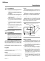
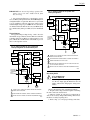
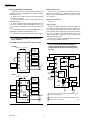
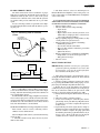
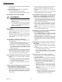
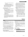
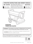
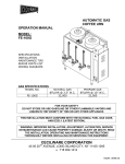
R4795A
Flame Safeguard
Primary Controls
The R4795A Protectorelay™ Primary Control
provides solid state electronic flame safeguard
protection for commercial and industrial gas or oil
burners. It provides a prepurge period before each
start, and intermittent pilot.
■ Solid state circuitry eliminates vacuum tube replacement and increases resistance to vibration. Application of power not required during Off cycle; no tube
warmup before starting.
■ Easy-to-replace plug-in components result in faster
service and reduced inventory.
■ Flame current jack, located on the amplifier, provides
means of plugging in a microammeter to measure the
flame signal with system operating.
■ Easy mounting and removal through use of captive
mounting screws, which also serve as electrical
connections.
■ Durable thermoplastic mounting base.
■ Models available with -40°F (-40°C) temperature
rating.
■ 120V models meet the requirements of Underwriters Laboratories Inc. Standard 795 for mechanical
draft and atmospheric burner inputs from 400,000 to
2,500,000 Btu.
■ Meets Underwriters Laboratories Inc. requirements
for oil burner group 8 when 30, 60, or 90 second prepurge timer is used.
■ Selection of solid state, plug-in prepurge timers provides 7, 10, 30, 60, or 90 second prepurge time.
■ Includes terminals for connection of air flow switch
to prove airflow before prepurge period starts, during purge, and during the entire Run period.
■ Choice of interchangeable, color-coded, solid state,
plug-in flame signal amplifiers allows use with rectification or ultraviolet type flame detectors.
■ Safe-start feature prevents start when flame or flame
simulating condition is present.
■ Recycles through prepurge if the flame goes out
while burner is running. If pilot flame is not reestablished, safety switch trips and locks out system.
■ A tripped safety switch must be manually reset to
restore operation.
■ Push-to-reset safety switch is dust-resistant enclosed.
■ Optional spdt alarm contacts operate external alarm
on safety switch lockout.
■ Ignition interference circuit (rectification amplifier
only) protects electronic network from high voltage
ignition crossover and provides visual indication
when interference occurs.
S.Y. • Rev. 12-94 • ©Honeywell Inc. 1994
CONTENTS
Specifications ................................................. 2
Ordering Information ..................................... 2
Installation ..................................................... 4
Checkout ......................................................... 8
Operation ..................................................... 11
Troubleshooting ........................................... 11
Service .......................................................... 13
1
60-2285-7
60-2285—7
R4795A
SPECIFICATIONS • ORDERING INFORMATION
Specifications
R4795A Flame Safeguard Primary Control recycles once
after flame failure to try to re-establish pilot before lockout.
Use with R7289A Amplifier and rectifying flame rod, rectifying photocell, or C7012A,C Purple Peeper Ultraviolet
Flame Detector; or with R7290A Amplifier and C7027A,
C7035A, or C7044A Minipeeper Ultraviolet Flame Detector.
Power Consumption (at 60 Hz):
6.0W max using rectifying flame rod or photocell.
8.0W max using ultraviolet flame detector.
FLAME FAILURE RESPONSE TIME: 0.8 or 3 seconds
nominal, as ordered.
SAFETY SWITCH TIMING (LOCKOUT TIMING): 15 seconds nominal.
RECYCLE TIME: Almost immediate after Flame Failure
Response Time.
FLAME ESTABLISHING PERIOD: May last up to safety
switch lockout time or until flame is recognized by
device.
ALARM CONTACTS (Optional): Isolated spdt contacts.
Male quick-connect terminals (female quick-connects
included). See Terminal Ratings. –40°F (–40°C) models
have isolated spdt alarm contacts.
AMBIENT TEMPERATURE RATINGS:
Minimum: -20°F (-29°C). Special models to -40°F (-40°C).
Maximum: +125°F (52°C) at 60 Hz; +115°F (46°C) at
50 Hz. -40°F (-40°C) models have maximum ambient
of +115°F (46°C) at 60 Hz, +105°F (40°C) at 50 Hz.
Subtract 10°F (6°C) when optional alarm contacts are
included.
ELECTRICAL RATINGS:
Voltage and Frequency: Single voltage models only:
100V, 120V, 200V, 220V, 50/60 Hz. As ordered.
Ordering Information
When purchasing replacement and modernization products from your TRADELINE® wholesaler or your distributor, refer to the
TRADELINE® catalog or price sheets for complete ordering number, or specify:
1. Order number.
3. Flame failure response time.
2. Voltage and frequency.
4. Alarm contacts, if desired (included with -40°F [-40°C] models.)
Order separately:
1. R7289A Rectification Amplifier,
3. Plug-in prepurge timer model number
or R7290A Ultraviolet Amplifier.
and timing (7, 10, 30, 60, or 90 seconds).
Specify flame failure response time.
4. Q270A1024 Mounting Subbase.
2. Flame detector to match amplifier.
5. Accessories, if desired.
If you have additional questions, need further information, or would like to comment on our products or services, please write or phone:
1. Your local Honeywell Home and Building Control sales office (check white pages of phone directory).
2. Home and Building Control Customer Logistics
Honeywell Inc., 1985 Douglas Drive North
Minneapolis, Minnesota 55422-4386
In Canada—Honeywell Controls Limited/Honeywell Limitée, 35 Dynamic Drive, Scarborough, Ontario M1V 4Z9. International
sales and service offices in all principal cities of the world. Manufacturing in Australia, Canada, Finland, France, Germany, Japan,
Mexico, Netherlands, Taiwan, United Kingdom, U.S.A.
60-2285—7
2
R4795A
SPECIFICATIONS
TERMINAL RATINGS:
a
Terminal
Load
3
Pilot Valve
Rating
125 VA pilot duty.
Intermittent Ignitiona
360 VA.
4
Interrupted Ignition
360 VA.
5
Main Fuel Valve(s)
125 VA pilot duty, or 25 VA pilot duty plus one or more motorized
valves with total rating up to 400 VA opening, 200 VA holding.
6-7
Airflow Switch
8
Fan or Burner Motor
9.8A full load, 58.8A locked rotor (inrush) at 120 Vac. 4.9A full
load, 29.4A locked rotor (inrush at 220 and 240 Vac.
Isolated Spdt Alarm
Terminals (Optional)
Alarm
3A at 24 volts, or 1A at 120 volts, in a suitable wiring enclosure.
0.6A at 30 Vdc.
When ignition is connected to terminal 3, terminal 4 cannot be used.
118702E Remote Reset Cover, 120 Vac, 60 Hz
202471C Reset Cover for R4795A
ADDITIONAL CONTROLS:
Order all additional controls separately:
Q270A1024 Mounting Subbase.
Plug-In Flame Signal Amplifiers, Rectification Type
(Green Backplate): For use with C7004B C7005A,
and B, C7008A, or Q179A,C Rectifying Flame Rods
(for gas); C7003A, C7010A, C7013A or C7014A
Photocells (for oil); or C7012A,C Purple Peeper Ultraviolet Flame Detectors (for gas or oil).
R7289A1004 Amplifier: 3 sec nominal flame failure
response.
R7289A1012 Amplifier: 0.8 sec nominal flame failure
response.
R7289A1020 Amplifier: 3 sec nominal flame failure
response, -40°F (-40°C) ambient temperature.
Ultraviolet Type (Purple Backplate): For use with C7027A,
C7035A or C7044A Minipeeper Ultraviolet Flame
Detectors (for gas or oil).
R7290A1001 Amplifier: 3 sec nominal flame failure
response.
R7290A1019 Amplifier: 0.8 sec nominal flame failure
response.
R7290A1027 Amplifier: 3 sec nominal flame failure
response, -40°F (-40°C) ambient temperature.
ST71A Plug-In Prepurge Timer (ordered separately):
Minimum Timings: 7, 10, 30, 60, and 90 seconds (as
ordered).
Maximum Timings: 8.4, 12, 36, 72, and 108 seconds
at room ambient temperature.
Recommended Limits: L404A; L604A,L; L4006A,C,E;
L4008A,E,F; L6006A,B: These controllers were
Underwriters Laboratories Inc. tested for breaking
loads only, at 120 Vac, for the total rating of 9.8A
full load, plus 360VA ignition, plus 250 VA pilot
duty.
Flame Detector: As specified in Plug-In Flame Signal
Amplifiers listed above.
NOTE: Allowable inrush can be up to ten times the pilot
duty rating.
Example:
Pilot duty rating = 125 VA.
At 120V, running current is 125/120 = 1.05A.
Maximum allowable inrush is 10 times 1.05 = 10.5A.
DIMENSIONS (Includes Cover and Subbase): Approximately 5 x 5 x 5 in. (127 x 127 x 127 mm).
MOUNTING: Q270A1024 Subbase. Ordered separately.
APPROVALS:
Underwriters Laboratories Inc Listed: 120V models using 30, 60, or 90 second prepurge timers including –
40°F (–40°C) rated models; file no. MP268, guide
no. MCCZ.
Underwriters Laboratories Inc. Component Recognized:
120 volt models using 7 or 10 second prepurge timers
including -40°F (-40°C) rated models; file no. MP268,
guide no. MCCZ2.
Canadian Standards Association Certified: 120V models only, including -40°F (-40°C) rated models; file
no. LR95329.
Factory Mutual Approved: R4795A 120V models; report no. 18774. -40°F (-40°C) rated models; report
no. 19608.1.
American Gas Association Design Certified: File no. 21-6
(F and F1).
ACCESSORIES:
W136A Test Meter (includes 117053 Meter Connector
Plug).
Flame Simulator:
203659 Ultraviolet
121708 Rectification
123514B Ultraviolet
117053 Meter Connector Plug
FSP1535 Tester for operational check
Q624 Solid State Spark Generator
3
60-2285—7
R4795A
INSTALLATION
Installation
CAUTION
Vibration
Do not install the R4795A where it could be subject to
excessive vibration. Vibration shortens the life of the electronic and mechanical components.
1. Installer must be a trained, experienced, flame
safeguard control service technician.
2. Disconnect power supply before beginning installation to prevent electrical shock and equipment damage.
3. All wiring must comply with applicable local
electrical codes, ordinances, and regulations.
4. Voltage and frequency of the power supply
connected to this control must agree with those
marked on the device.
5. Loads connected to the control terminals must
not exceed those listed in the Specifications
section.
6. All external timers must be Listed or Component Recognized by authorities having jurisdiction for the specific purpose for which they are
used.
7. Some authorities having jurisdiction prohibit
the wiring of any limit or operating contacts in
series with the main fuel valve(s).
8. Perform all required checkout tests after installation is complete.
Weather
The R4795A is not designed to be weathertight. If it is
installed outdoors, use a suitable weathertight enclosure.
Mounting The Subbase
Locate the subbase where ambient temperature is within
the specified rating.
Mount the subbase so the top and bottom are horizontal
and the back is vertical. The subbase can lean backward as
much as 45 degrees when necessary. See Fig. 1.
Fig. 1—Subbase mounting dimensions in in.
(mm).
VERTICAL
HORIZONTAL
45 DEGREES
MAXIMUM LEAN
Follow the burner manufacturer’s instructions, if supplied. Otherwise proceed as follows.
2-7/8
(73.0)
CAUTION
Ultraviolet sensing tubes have a life expectancy of
40,000 hours of continuous use within the ambient
temperature and voltage ratings. Worn out ultraviolet sensing tubes can result in failure of the
sensing tube to properly discriminate between flame
conditions.
4-1/8 (104.8)
KNOCKOUTS (9) FOR
1/2 IN. (13) CONDUIT
WIRING TO SUBBASE
1. All wiring must comply with applicable codes, ordinances, and regulations. All wiring to the Q270A Universal
Mounting subbase must be NEC Class 1.
2. When wiring the Q270A for use with the R4795A, use
the terminal designations 8, 7, and 6 (printed in yellow).
3. For normal installations, use moisture-resistant No. 14
wire suitable for at least 167°F (75°C).
4. For high temperature installations, use moisture-resistant No. 14 wire selected for a temperature rating above
the maximum operating temperature for all but the ignition
and flame detector F leadwires.
a. For the ignition, use Honeywell Specification no.
R1061012 Ignition Cable or equivalent. This wire is
rated at 350°F (175°C) for continuous duty, and up to
500°F (260°C) for intermittent use.
b. For the flame detector F leadwire, use Honeywell
Specification no. R1298020 or equivalent. This wire
is rated up to 400°F (205°C) for continuous duty. It is
tested for operation up to 600V and breakdown up
to 7500V.
For systems using R4795A with R7290 Amplifiers, use
C7027, C7035 and C7044 Flame Detectors only on burners
that cycle On and Off at least once every 24 hours. Appliances with burners that remain on for 24 hours continuously
or longer should use the C7012E Flame Detector with the
R7247C Amplifier or the C7076A Flame Detector with the
R7476A Amplifier as the ultraviolet flame detection system.
LOCATION
Temperature
Install the R4795A where the surrounding temperatures
remain within the Ambient Operating Temperature Ratings
listed in the Specifications section.
Humidity
Install the R4795A where the relative humidity never
reaches the saturation point. Condensation of moisture on
the R4795A may cause enough leakage to short the flame
signal to ground and prevent the burner from starting.
60-2285—7
M8681
4
R4795A
INSTALLATION
IMPORTANT: Do not run high voltage ignition transformer wires in the same conduit with the flame
detector wiring.
Fig. 3—Wiring hookup of oil system with
interrupted ignition.
5. For ignition installations in a contaminating environment, use Honeywell Specification no. R1239001 High Tension Ignition Cable or equivalent. This wire is very resistant
to severe conditions of oil, heat, and corona, and is tested to
withstand high voltages up to 25,000V rms in a salt bath for
one minute without breakdown. It is rated at 200°F (93°C)
for continuous duty and up to 350°F (75°C) for intermittent
use.
BURNER
MOTOR
8
AIR FLOW
SWITCH
7
5
2ND STAGE
OIL VALVE(S)
4
IGNITION
2K3
2
2K2
6
3
1K4
Wiring Hookups
The typical wiring hookups in Fig. 2 and 3 show the
internal line voltage schematic. Contact 3K2 closes when the
controller calls for heat. 1K4 closes when prepurge is complete. 2K2 breaks and 2K3 makes when flame is proven.
Also see the Operation section.
4
3
1ST STAGE
OIL VALVE(S)
3K2
F
TO FLAME
DETECTOR
(PHOTOCELL
OR UV)
FLAME
AMPLIFIER
G
1
CONTROLLER
2
LIMIT(S)
5
Fig. 2—Wiring hookup of gas system with
interrupted ignition and intermittent pilot.
R4795A
BURNER
MOTOR
AIR FLOW
SWITCH
5
8
2K3
4
7
MAIN FUEL
VALVE(S)
IGNITION
L2
1
L1
(HOT)
1
POWER SUPPLY. PROVIDE DISCONNECT MEANS AND OVERLOAD
PROTECTION AS REQUIRED.
2
FOR INTERMITTENT IGNITION,CONNECT IGNITION TO TERMINAL 3.
3
IMMEDIATE OPENING OIL VALVE V4046B.
4
OPTIONAL DELAYED OPENING OIL VALVE V4046A OR V4046B WITH
ST70A ELECTRONIC TIME DELAY.
5
REFER TO SPECIFICATIONS SECTION FOR RECOMMENDED LIMITS.
2
2K2
6
3
1K4
PILOT
VALVE
3K2
TO FLAME
DETECTOR
(FLAME ROD
OR UV
DETECTOR)
M8683
F
FLAME
AMPLIFIER
G
1
Retrofitting R4795
CONTROLLER
CAUTION
2
LIMIT(S)
3
Make wiring connections as specified in Fig. 2, 3,
or 4. Do not simply plug the R4795 into the old
subbase without first changing the wiring at the
subbase.
R4795A
L2
1
L1
(HOT)
1
POWER SUPPLY. PROVIDE DISCONNECT MEANS AND OVERLOAD
PROTECTION AS REQUIRED.
2
FOR INTERMITTENT IGNITION, CONNECT IGNITION TO TERMINAL 3.
3
REFER TO SPECIFICATIONS SECTION FOR RECOMMENDED LIMITS.
Observe the following when retrofitting the R4795:
1. Requires a line voltage controller capable of switching
the entire connected electrical load.
2. Delayed opening oil valve may be retained but its
delay is not necessary. Integral ST71A Purge Timer meets
the intent of a delayed opening valve.
3. Refer to Fig. 2, 3 or 4 for proper wiring connections.
M8682
5
60-2285—7
R4795A
INSTALLATION
Replacing RA890E,F,G with R4795A
1. Disconnect all wires from terminal 1, and splice with
solderless connector. (If RA890 has no terminal 1 wiring,
disregard this step.)
2. Remove line voltage controller wire from terminal 6
and connect to terminal 1.
3. Move burner motor connection from terminal 3 to terminal 6 on subbase.
4. Remove jumper from T and T and install air switch. If
low voltage control was wired to RA890 T-T, remove low
voltage control and install line voltage control as shown in
Fig. 4.
5. If R482D Relay was used with RA890E, remove it.
The R482D is redundant when R4795D is used.
6. Check for proper operation through at least two cycles.
R4795C Replacement
In most cases, the R4795A can directly replace the
R4795C. For standing pilot applications where the pilot
flame was detected during the off cycle, install a relay as
shown in Fig. 5.
Flame Detector Wiring
See Fig. 6.
Alarm Contacts
Models with alarm contacts have three male quick-connect terminals. Three female quick-connect terminals are
provided for field installation. To connect leadwires to the
female quick-connects, strip 1/4 inch (6.4 mm) insulation
from end of leadwire; insert into the quick-connect, and
crimp securely with a crimping tool. Fig. 7 shows proper
alarm terminal connections.
If a line voltage alarm is used with the R4795, mount the
entire control in a suitable enclosure.
Fig. 4—Replacing RA890E,F,G with R4795A on
gas or oil burner.
REPLACING RA890 WITH R4795 ON GAS OR OIL BURNER
Fig. 5—When R4795A replaces R4795C in a
standing pilot application, install relay 1R to
prevent detection of pilot flame during burner
off cycle.
BEFORE
CONTROLLER
HIGH LIMIT
MAIN GAS
VALVE OR
2ND STAGE
OIL VALVE
6
5
T
4
IGNITION
TRANSFORMER
T
FLAME
DETECTOR
3
BURNER
MOTOR
BURNER
MOTOR
2K3
7
2K2
MIAN FUEL
VALVES
4
PILOT OR
OIL VALVE
F
5
8
L1
(HOT)
1
3
AIR FLOW
SWITCH
120V
G
1R
1K4
6
L2
2
3K2
1R1
RA890 WITH Q270
F
TO FLAME
DETECTOR
AFTER
FLAME
AMPLIFIER
G
CONTROLLER
6
AIR FLOW
SWITCH
8
(FLAME ROD
OR UV
DETECTOR)
MAIN GAS
VALVE OR
2ND STAGE
OIL VALVE
T
F
7
6
3
2
R4795A
3
L2
PILOT OR
OIL VALVE
1
120V
2
L2
M8684
60-2285—7
2
BURNER
MOTOR
L1
(HOT)
RA4795 WITH Q270
CONTROLLER
LIMIT(S)
4
SODERLESS
CONNECTION
G
1
5
IGNITION
TRANSFORMER
T
FLAME
DETECTOR
HIGH LIMIT
6
1
L1
(HOT)
1
POWER SUPPLY. PROVIDE DISCONNECT MEANS AND OVERLOAD
PROTECTION AS REQUIRED.
2
REFER TO SPECIFICATIONS SECTION FOR RECOMMENDED LIMITS.
3
LOW VOLTAGE CIRCUIT OMITTED.
M8685
R4795A
INSTALLATION
Fig. 6—Flame detector wiring.
Fig. 7—Alarm terminal connections.
PHOTOCELL
FLAME ROD
X F
X F
X G
X G
R4795
ALARM TERMINALS (OPTIONAL)
C7012 ULTRAVIOLET DETECTOR
N.C.
N.O.
COM
L1
(HOT)
ALARM
2 POWER
SUPPLY
LINE OR
LOW VOLTAGE
ALARM
1
BLUE
YELLOW
BLACK
BLACK
1
POWER
SUPPLY
WHITE
1
IF A LINE VOLTAGE ALARM IS USED, THE R4795 MUST BE
MOUNTED IN A SUITABLE ENCLOSURE.
2
POWER SUPPLY MUST MATCH THE ELECTRICAL RATINGS OF THE
ALARM. PROVIDE DISCONNECT MEANS AND OVERLOAD
PROTECTION AS REQUIRED.
M8687
CAUTION
C7027, C7035, OR C7044
ULTRAVIOLET FLAME DETECTOR
BLUE
1
X F
X G
L2
Do not overtighten the mounting screws because
damage to the circuit board can result. Maximum
recommended torque is 10 lb-in. (1.13 N•m).
XF
XG
C7027, C7035, AND C7044 FLAME DETECTOR LEADS ARE COLOR
CODED BLUE AND WHITE. THE BLUE LEAD MUST BE CONNECTED
TO THE F TERMINAL AND THE WHITE LEAD MUST BE CONNECTED
TO THE G TERMINAL. THIS CIRCUIT IS DC AND THE UV SENSING
TUBE IS POLARITY SENSITIVE. REVERSING THE LEADS EVEN
MOMENTARILY CAN DAMAGE OR DESTROY THE UV TUBE.
Replace cover and securely tighten thumbscrew.
Fig. 8—R4795 and Q270 Subbase.
M8686
CAPTIVE MOUNTING
SCREWS (10)
Q270
SUBBASE
Mounting R4795 On Subbase
Make sure that the power supply is disconnected.
Loosen the thumbscrew and remove the cover (see Fig. 8).
Position the R4795 over the Q270 Subbase. Start all ten
mounting screws and tighten uniformly. These screws complete electrical circuits (terminal 1 excepted) and hold the
R4795 to the subbase.
SAFETY SWITCH
RESET BUTTON
IN COVER
TERMINAL
BLOCKS
COVER
PURGE TIMER
THUMBSCREW
AMPLIFIER
M8688
7
60-2285—7
R4795A
CHECKOUT
Checkout
CAUTION
Fig. 10—Internal view showing amplifier and
test jack for flame current test.
Use extreme care while testing the R4795; line
voltage can be present on most terminals when the
power is On.
ARC-GAP IGNITION INTERFERENCE
PROTECTION (R7289 RECTIFICATION
AMPLIFIER ONLY)
ST71A
PLUG-IN
PURGE
TIMER
CHECKOUT SUMMARY
The following list summarizes the checkout tests required for each type of installation. Instructions for each test
are included in this section.
Preliminary Inspection: All installations.
Flame Current Check: All installations.
Pilot Turndown Test: If a pilot must be proved before the
main fuel valves can open.
Hot Refractory Hold-in Test: Photocell oil installations
only.
Ignition Spark Response Test: All ultraviolet detector
applications.
Safe Shutdown Tests: All installations.
Refer to Fig. 2 to 3 for terminal location, and to Fig. 9 and
10 for location of component parts. Loosen thumbscrew to
remove cover.
PLUG-IN
AMPLIFIER
OPTIONAL
ALARM TERMINALS
CAPTIVE
MOUNTING
SCREWS
(10)
PLUG-IN
PURGE
TIMER
(ST71A)
SPRING
CLIP FOR
AMPLIFER
SAFETY
SWITCH
RESET
BUTTON
IMPORTANT: Anytime you reset the safety switch, wait at
least one minute after it trips to allow the heater to cool
before pushing in the reset button.
TRANSFORMER
PLUG IN AMPLIFIER
(R7289–GREEN–RECTIFICATION)
(R7290–PURPLE–ULTRAVIOLET)
M8680
PRELIMINARY INSPECTION
Make certain that:
1. Wiring connections are correct and all terminal screws
are tight. Use a meter to check the continuity of all circuits.
2. Flame detector is installed and positioned properly.
Consult the appropriate installation instructions.
3. Ambient temperature at flame detector does not exceed maximum rated temperature.
4. Correct combination of amplifier and flame detector is
used. Refer to Plug-In Flame Signal Amplifiers in Specifications section.
5. Burner is completely installed and ready to fire; fuel
lines are purged of air.
6. Combustion chamber and flues are clear of fuel.
7. Power is connected to system disconnect switch (master switch).
8. Safety switch is reset; push in and then release the
green safety switch.
9. All limits and interlocks are reset.
2K
1K
UNDER
COVER
AMPLIFIER
CONNECTORS
PURGE TIMER
CONNECTORS
Fig. 9—Internal components of R4795A.
3K
TEST JACK
CAUTION
M8679
Make initial pilot lightoff with manual main fuel
shutoff cock closed.
60-2285—7
8
R4795A
CHECKOUT
FLAME CURRENT CHECK
The flame current check is the best indicator of proper
flame detector application. Perform the check at the time of
installation, and at any time service is done on the system,
and at least once a month, or more often, while the system is
in operation. This prevents shutdowns due to poor flame
signal.
Test by connecting a W136 (or equivalent) to the amplifier and reading the flame current while the burner is operating. (Fig. 11).
2. The flame current is at least two microamperes for
R7289A Rectification Amplifier (color-coded green), or at
least 1.5 microamperes for an R7290A Ultraviolet Amplifier
(color-coded violet).
IF A STEADY READING OF AT LEAST MINIMUM
STRENGTH CANNOT BE OBTAINED, ONE OR MORE
OF THE FOLLOWING CONDITIONS CAN EXIST:
• Improper supply voltage.
• Defective flame detector wiring including:
— Open circuits.
— Short circuits.
— High resistance shorts caused by moisture, accumulated dirt, or an improper choice of detector leadwire for the particular installation.
• Improper sighting, improper viewing window, or dirty
viewing window for optical detectors.
• Improper application of a flame rod including:
— Insufficient ground area.
— Poor location of flame rod in flame.
— Excessive heat on flame rod insulator, greater than
600°F (316°C).
— Ignition interference.
• Improper application of a vacuum photocell including:
— Temperature over 165°F (74°C) at photocell.
— Dirty photocell envelope.
• Defective sensor.
Fig. 11—Connecting meter to read flame
current.
117053 METER
CONNECTOR PLUG
(SUPPLIED WITH W136)
PLUG-IN
AMPLIFIER
W136
CK
BLA
BLA
FLAME
CURRENT
TEST JACK
D
RE
CK
RED
IF 117053 METER CONNECTOR PLUG IS NOT AVALIABLE
(R7289A RECTIFICATION AMPLIFER ONLY)
PILOT TURNDOWN TEST
IMPORTANT: If the R4795 is used to prove a pilot flame,
perform the following Turndown Test to assure that
the main burner can be lit by the smallest pilot flame
that will hold in the 2K (flame) relay.
W136
F LEAD
FLAME
DETECTOR
G LEAD
BLACK
+
RED
F
1. Shut off the fuel supply to the main burner only by
closing the manual main burner shutoff cock. Do not shut off
fuel supply to the pilot valve.
2. Start the system by raising the setpoint of the controller (or pressing the START button). After prepurge is completed, the pilot will light and pull in the flame relay.
3. Reduce the size of the pilot flame to the turndown
condition by slowly closing the manual valve on the pilot gas
line. At the turndown condition, the pilot will be small
enough so it just barely holds in the flame relay (2K).
a. Slowly turn down the pilot until the flame relay drops
out.
b. Allow the control to complete prepurge.
c. As the control attempts to restart the pilot, turn the
pilot back up slowly just until relay 2K pulls back in.
You will have 15 seconds to complete this step before
lockout occurs.
d. Again turn the pilot down slightly but not enough so
the flame relay drops out. If the relay drops out, simply
allow the control to complete the purge period and
then turn the pilot back up to pull in the flame relay as
in step c. above. The closer the pilot is to the dropout
condition, the more conclusive the test will be.
G
R4795
M8689
Insert a 117053 Meter Connector Plug, wired color-tocolor to the W136 leadwires, into the test jack on the amplifier (Fig. 10). This automatically puts the microammeter in
series with the flame detector.
If an R7289A Rectification Type Amplifier is used and a
meter connector plug is not available, disconnect the flame
detector lead from the F terminal; then connect this lead to
the Black lead of the microammeter, and connect the Red
lead of the microammeter to the F terminal.
NOTE: If an R7290A Ultraviolet Type Amplifier is used, the
flame current cannot be read by connecting a microammeter in series with the F lead.
When reading the flame current, assure that the following
criteria are met:
1. The flame current is steady; meter does not vary more
than a needle width.
9
60-2285—7
R4795A
CHECKOUT
4. If relay 2K does pull in, resight the detector farther out
from the spark, or away from possible reflection. It may be
necessary to construct a barrier to block the ignition spark
from the detector view. Continue adjustments until flame
detector does not respond to the ignition spark.
CAUTION
Do not manually push in the relays.
4. Check that the pilot is lit and relay 2K is pulled in.
5. Open the manual main burner shutoff cock. Main
flame should light within one second. If the burner does not
light within one second, close the shutoff cock and shut off
power to the relay. Proceed to step 7.
6. If the burner lights, repeat step 5 two or three times to
verify lightoff.
7. If the lightoff is unsatisfactory, readjust the flame
detector to require a larger pilot flame to hold in the flame
relay. This usually requires:
a. Resighting a photocell or UV type detector farther
out on the axis of a pilot flame, or
b. Adjusting a flame rod detector so that a larger minimum pilot is required.
8. Repeat the entire turndown test until the flame is
established promptly in step 5.
9. Turn up the pilot to full flame at the test completion.
IMPORTANT: Repeat ALL required checkout tests after all
adjustments are complete. ALL tests must be satisfactory when the flame detector is in its FINAL position.
SAFE SHUTDOWN CHECKS
Limit Action
With the burner operating, lower the high limit setting to
simulate an overheated boiler or furnace. Normal shutdown
should occur. Restore the normal limit setting; the burner
should go through a normal prepurge and start.
Using manual reset limits is desirable to prevent the
system from cycling off the high limit and to assure that the
condition that caused the limit action is detected as soon as
possible.
Flame Failure
Let burner operate five minutes; then manually shut off
fuel supply to simulate flame failure. Relay should drop out
and fuel valve(s) close. The system will purge and then lock
out on safety. Let the safety switch cool for one minute;
reopen manual fuel valve, and reset safety switch. Burner
should start.
HOT REFRACTORY HOLD-IN TEST
(PHOTOCELL OIL INSTALLATIONS ONLY)
If hot refractory holds in the flame relay at the end of the
burner-on cycle, the system cannot restart until the relay
drops out. Check for hot refractory hold-in by observing the
flame relay for immediate dropout at the end of a long
burner-on period. If the relay does not drop out, resight the
photocell so it does not sight the refractory, or decrease
photocell sensitivity using aperture disks or filters.
Power Failure
Let the burner run five minutes. Then simulate power
failure by opening the line switch. All relays should drop out
and the fuel valves should close. After a minimum of five
seconds, close the line switch. The R4795 should go through
a normal cycle.
IGNITION SPARK RESPONSE TEST
(UV DETECTORS)
The flame relay should not respond (pull in) to ignition
spark. To determine flame detector sensitivity to ignition
spark, perform the following test:
1. Shut the pilot and main fuel manual valves.
2. Start the system by raising the controller setpoint or
pressing the START button. This should energize the ignition transformer so spark is produced between the electrode
and ground.
3. Check the flame relay 2K. The relay should not pull in.
The flame signal current should not be more than one-fourth
microampere.
60-2285—7
IMPORTANT: At the completion of all Checkout tests,
make sure that the R4795 is not on safety lockout, that
the pilot is turned up to its normal level, and that all
limit settings are correct. Operate the system through
one normal cycle. Replace cover and securely tighten
thumbscrew.
10
R4795A
OPERATION • TROUBLESHOOTING
Operation
NORMAL OPERATION (REFER TO FIG. 2 AND 3.)
Call for Heat (Limit Switch
Closed)
Terminal 1 energized. Relay 3K pulls in to close contact 3K2 and energize
terminal 8 fan or burner motor.
Airflow Proved
Low voltage airflow switch between terminals 6 and 7 closes to energize the
purge timer.
Prepurge Complete (7, 10, 30, 60,
or 90 Seconds)
Relay 1K pulls in to close contact 1K4 and energize terminal 3 (pilot valve, first
stage oil valve(s), or expanding pilot valve) directly and terminal 4 (ignition)
through the closed flame relay contact 2K2. Contact 1K1 closes to energize the
safety switch heater.
Flame Proven (Pilot or First Stage
Oil)
R4795A: Relay 2K pulls in. Contact 2K2 opens to cut off ignition, contact 2K3
closes to energize the main fuel valve(s) or second stage oil valve(s). Contact
2K1 opens to de-energize the safety switch heater and reset the purge timer.
Controller Satisfied
All relays drop out; systems shuts down.
SAFETY OPERATION
Flame Failure
R4795A: Relays 1K and 2K drop out. Contact 1K4 opens to de-energize
terminals 3, 4, and 5. If air is still proven, the prepurge period begins. After
prepurge, one attempt is made to start the burner.
Airflow Failure
If airflow fails at any time during the operating cycle, relay 1K drops out.
Contact 1K4 opens to de-energize terminals 3, 4, and 5. Only terminal 8, fan or
burner motor, remains powered. If air is re-established, the prepurge period
starts and the startup sequence is repeated.
Prepurge Timer Failure
If the plug-in purge timer is not properly seated, or is not functioning properly,
the fan motor will start on a call for heat, but the 1K relay will not pull in. The
result will be a continuous purge (safe failure).
Hot Refractory Hold-in (Photocell
Installations)
If hot refractory holds in the flame relay at the end of the running cycle, startup
is prevented until the hot refractory no longer holds in the flame relay.
Troubleshooting
The first step in troubleshooting the R4795A is to determine the location of the system trouble. Reset the safety
switch and operate the system on a normal start. Refer to the
Normal Operation subsection in the Operation section. Observe the operation carefully to determine at what point the
trouble occurs. Then refer to the Trouble List in the Trouble
List section and follow the troubleshooting procedure.
3. Reset the safety switch (push in and then release the
small round button that extends through the plastic safety
switch cover; see Fig. 9).
TROUBLE LIST
Compare the following list of troubles with the actual
deviations from normal operating sequence. Select the applicable letter(s) and proceed to the corresponding Troubleshooting Procedure(s).
A. Relay 3K does not pull in on a call for heat.
B. Relay 3K pulls in but the burner motor does not start.
C. Burner motor starts but prepurge does not stop at end
of purge timing (relay 1K does not pull in).
D. Relay 1K pulls in but the pilot does not light, ignition
does not occur, or expanding pilot valve does not
open.
E. Pilot lights but relay 2K does not pull in (control locks
out without lighting the main burner).
IMPORTANT: At the completion of any troubleshooting
procedure, be sure to perform the Checkout Tests
listed in the Checkout section.
PRELIMINARY INSPECTION
1. Disconnect power to the R4795 by opening the system disconnect switch.
2. Remove the R4795 cover. Make sure all mounting
screws are tight, and that the plug-in amplifier and purge
timer are properly seated; refer to Fig. 10.
11
60-2285—7
R4795A
TROUBLESHOOTING
3. Check the position of the flame relay. If relay 2K is
pulled in, check for flame simulating condition.
4. If the flame relay is not pulled in, clean the 2K relay
contacts.
5. Replace the purge timer with one of the same timing.
If problem still continues, replace the R4795.
F. Pilot lights and relay 2K pulls in but the main burner
does not light.
G. Relay 2K remains in after flame is extinguished.
H. Miscellaneous problems:
1. Repeated lockouts or control failures.
2. Ignition interference (flame rod installations only).
D. Relay 1K pulls in but the pilot does not light, ignition
does not occur, or expanding pilot valve does not open
1. Make sure that all manual fuel valves are open.
2. Check voltage between terminals 3 and 2, or 4 and 2,
as applicable. (Terminal 3 is used for pilot or first stage
oil valve; terminal 4 for ignition.) Check must be made
before control locks out on safety.
3. If zero voltage, clean the 1K and 2K relay contacts;
then recycle the system and recheck the voltage at terminal 3 or 4. If terminals cannot be powered, replace the
R4795.
4. If correct voltage at terminals 3 and 4, check the pilot
valve and ignition and the circuits.
TROUBLESHOOTING PROCEDURES
CAUTION
1. Use extreme care while troubleshooting the
R4795; line voltage is present on most contacts
when power is On.
2. Open the master switch before removing the
cover, cleaning contacts, removing R4795 from
subbase, or reinstalling R4795 on subbase. See
Fig. 9 for relay location.
IMPORTANT:
1. Clean contacts only when instructed to do so in a
troubleshooting procedure. Follow the instructions in
Contact Cleaning section.
2. If, after completing an applicable Troubleshooting
Procedure, proper operation still cannot be obtained,
replace the R4795 (except amplifier and purge timer,
unless noted).
E. Pilot lights but relay 2K does not pull in (control locks
out without lighting the main burner)
1. Use a 121708 Rectification or a 203659 or 123514B
Ultraviolet Flame Simulator to check the flame relay.
Follow the instructions for the simulator.
2. If no flame simulator is available, do a flame current
check. If the flame current is satisfactory, replace the
R4795. If the flame current is not satisfactory, recheck
all items.
A. Relay 3K does not pull in on a call for heat
1. Check for power at terminals 1 and 2 with the controller calling for heat.
a. Voltage must be within plus 10 to minus 15 percent
of the rated voltage for dependable operation.
b. If voltage is zero, check the continuity of the limit
and controller contacts and check the power supply. Look for blown fuses, open switches, and bad
wiring connections.
2. If voltage at terminals 1 and 2 is satisfactory and relay
3K will not pull in, clean the 1K and 3K relay contacts.
Press safety switch button several times to clean the
contacts. If trouble persists, replace the R4795.
F. Pilot lights and relay 2K pulls in but the main burner
does not light
1. Check that the manual main fuel valves are all open.
2. Check the voltage at terminal 5 when the 2K relay
pulls in.
a. If normal voltage at terminal 5, check the main
valve and the external valve circuit.
b. If zero voltage at terminal 5, clean the 2K relay
contacts. If terminal 4 cannot be powered, replace
the R4795.
G. Relay 2K remains in after flame is extinguished
1. If the flame detector is a rectifying flame rod, install a
new plug-in amplifier.
2. If the flame detector is a rectifying photocell or C7012
Ultraviolet Detector, plug the back end of the flame
simulator into the jack of the plug-in amplifier.
a. If that does not cause relay 2K to drop out, install a
new plug-in amplifier.
b. If plugging into the meter jack causes relay 2K to
drop out, the trouble is caused by hot refractory
hold-in, detector failure, or other flame simulating
conditions.
(1) Resight the photocell at a cooler or more remote area of the refractory.
(2) Recheck the flame detector current for the
condition recommended in the Checkout section. Replace the detector if necessary.
B. Relay 3K pulls in but the burner motor does not start
1. Check for power at terminal 8 when the 3K relay
pulls in.
a. If terminal 8 is not powered, clean the 3K relay
contacts and recheck for power. If terminal 8 cannot be powered, replace the R4795.
b. If terminal 8 is powered, check the fan or burner
motor.
C. Burner motor starts but prepurge does not stop at end
of purge timing (relay 1K does not pull in)
1. Check the seating of the plug-in purge timer.
2. Check that the airflow switch contacts are making.
Approximately 20 Vdc should appear between terminals 7 (plus) and G (minus) when airflow switch contacts are made.
60-2285—7
12
R4795A
TROUBLESHOOTING • SERVICE
How detected. The arc gap circuit in the rectification amplifier (Fig. 10) protects the R4795 from ignition interference; however, it also prevents operations
when ignition interference is present above the arcing
level of the device. If a shutdown is caused by ignition
interference, the arc gap protector glows.
Continuous interference below the arcing level can
be detected by reading the flame current with the pilot
and ignition on; then with only the pilot on. Any substantial difference indicates the presence of ignition
interference.
Intermittent ignition interference may be due to
very turbulent air in the ignition electrode area. For
arc-over elsewhere, examine the electrodes for spacing and for unusual dirt conditions or dust accumulations between the ignition leads and flame leads.
How eliminated (tabulated in order of importance).
1. Provide adequate flame grounding area.
2. Be sure the ignition electrode and the flame rod
are on opposite sides of the grounding area.
3. Check for the correct spacings on the ignition
electrode. Spacing should be 1/16 in. (1.6 mm)
to 3/32 in. (2.4 mm) for 6,000V systems; 1/8 in.
(3.2 mm) to 3/16 in. (4.8 mm) for 10,000V
systems.
4. Eliminate any marginal spacings at other areas
along the lead routes. Replace any deteriorated
leads.
(3) Remove any flame simulating condition such
as false light.
(4) Note that any change made in the detector or its
sighting requires a pilot turndown test.
3. If using an R7290 Ultraviolet Amplifier, replace the
amplifier and recheck the flame relay dropout time. If
the flame relay dropout timing is still excessive, replace the detector and check its wiring.
4. If trouble persists, replace the R4795.
H. Miscellaneous problems
1. Repeated lockouts or control failures: The most common causes of repeated failures of the control or flame
detector, or repeated lockouts are:
a. High ambient temperatures over 125°F (52°C).
Subtract 10°F (6°C) for alarm contacts and 10°F
(6°C) for 50 Hz operation. -40°F (-40°C) models
have a maximum ambient of +115°F (46°C) at
60 Hz, +105°F (40°C) at 50 Hz.
b. Supply voltage variation greater than plus 10 to
minus 15 percent.
c. Marginal flame signal.
d. Faulty flame detector.
2. Ignition interference (flame rod installations only)
What it is. Ignition interference is a false signal
from a spark ignition source superimposed on the
basic flame signal. It is normally associated with a
marginal flame reading, and usually caused by a marginal flame ground.
Service
GENERAL
1. Only qualified personnel should attempt to service
heating equipment or controls.
2. Perform all checks required in the Checkout section
when replacing the R4795, or when relighting or restoring
power to the system after shutdown.
3. Captive mounting screws carry current; always disconnect power before loosening or tightening the mounting
screws.
4. On each service call, check the controller for the approximately correct calibration and differential; assure it is
mounted securely (see Controller installation instructions).
5. Never use oil on any part of the R4795.
6. When cleaning the burner, clean the flame detector.
7. DO NOT MANUALLY PUSH IN THE R4795
RELAYS. This may damage the relays and it is an unsafe
practice because it overrides the protective features of the
relays. Clean relay contacts only as instructed following.
operating conditions (dirt and heat especially), and the cost of
a nuisance shutdown. Include the following in any program:
Annually replace the vacuum tubes in the C7012 Flame
Detector (if used).
Perform a flame failure check and pilot turndown test
whenever the burner is serviced, and at least annually.
Inspect and clean the detector and any viewing windows
as often as required by soot accumulation and heat
conditions at the detector.
Do a flame current check at least monthly, and more often
where a shutdown may be costly.
Clean contacts only when required by failure to operate
properly.
CONTACT CLEANING
CAUTION
Open the master switch before removing cover or
cleaning contacts. Line voltage is present on most
contacts when power is on.
PERIODIC MAINTENANCE
The specific maintenance schedule setup will depend on
several factors including type of equipment being controlled,
13
60-2285—7
R4795A
SERVICE
2. Some leave an oily residue that will collect dust and
dirt. The residue will also break down to form various
carbonaceous products. Either result will cause early contact
failure.
Do not use an abrasive (sand paper stock, file, etc.) or a
burnishing tool to clean contacts. Its use can cause early
contact failure for these reasons:
1. Some relay contacts are plated with gold for increased
reliability. Burnishing can quickly remove the plating.
2. The radii or points of the contacts are designed with
specific shapes to best serve the intended functions of the
contacts. Burnishing can rapidly alter these contact configurations.
3. Use of an abrasive loosens fine particles of the contact
material that adhere to the surface of the contract, thus increasing its resistance.
4. Contact specifications (contact pressures, press-back,
and gaps) are carefully controlled during manufacturing to
assure maximum contact life. Burnishing can easily change
these specifications.
IMPORTANT:
1. Do not clean contacts unless absolutely necessary.
2. Use only Honeywell Contact Cleaner part no. 132569.
Do not use any other type of contact cleaner.
3. Use extreme care to avoid bending the contacts or
changing the specifications or configuration in any
way.
4. Do not use an abrasive or a burnishing tool to clean
contacts.
5. Do not use hard paper such as a business card to clean
contacts.
If relay contacts must be cleaned, use only Honeywell
Pressurized Contact Cleaner, part no. 132569. Honeywell’s
chemical analysis laboratory has found this cleaner to be
acceptable for this task. Directions for using this cleaner are
printed on the can.
Do not risk using any other types of contact cleaners.
Honeywell’s chemical analysis laboratory tested other pressurized type contact cleaners but did not approve them for
these reasons:
1. Some had solvents that could deteriorate plastic parts
and wire insulation.
60-2285—7
14
15
60-2285—7
Home and Building Control
Honeywell Inc.
1985 Douglas Drive North
Golden Valley, MN 55422
Printed in United States
Home and Building Control
Honeywell Limited—Honeywell Limitée
740 Ellesmere Road
Scarborough, Ontario
M1P 2V9
www.honeywell.com/bbc