1
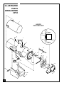
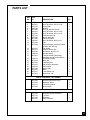
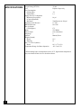
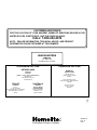
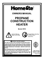
OWNERS MANUAL
PROPANE
CONSTRUCTION
HEATER
Model HP35
!
Indicates Warning,
Danger, and Caution
Read all Safety, Operating,
and Maintenance
Instructions
Man Reading Icon
!
HSYMBOL2
GENERAL HAZARD WARNING:
FAILURE TO COMPLY WITH THE PRECAUTIONS AND INSTRUCTIONS PROVIDED WITH THIS HEATER, CAN RESULT IN DEATH,
SERIOUS BODILY INJURY AND PROPERTY LOSS OR DAMAGE
FROM HAZARDS OF FIRE, EXPLOSION, BURN, ASPHYXIATION,
CARBON MONOXIDE POISONING, AND/OR ELECTRICAL
SHOCK.
ONLY PERSONS WHO CAN UNDERSTAND AND FOLLOW THE
INSTRUCTIONS SHOULD USE OR SERVICE THIS HEATER.
IF YOU NEED ASSISTANCE OR HEATER INFORMATION SUCH
AS AN INSTRUCTIONS MANUAL, LABELS, ETC. CONTACT THE
MANUFACTURER.
®
FIRST EDITION
PART NO. 18994
Printed In U.S.A.
Price $1.00
CONTENTS
SECTION
PAGE
Safety Information ......................................................................... 2
Product Identification .................................................................... 4
Unpacking ...................................................................................... 4
Theory of Operation ...................................................................... 5
Propane Supply .............................................................................. 5
Installation ..................................................................................... 6
Ventilation ..................................................................................... 7
Operation ....................................................................................... 7
Storage ........................................................................................... 9
Maintenance .................................................................................. 9
Troubleshooting ............................................................................. 10
Service Procedures ........................................................................ 11
Illustrated Parts List ....................................................................... 14-15
Specifications ................................................................................. 16
SAFETY
INFORMATION
WARNING ICON
G 001
WARNINGS
WARNING: FIRE, BURN, INHALATION, AND EXPLOSION
HAZARD. KEEP SOLID COMBUSTIBLES, SUCH AS BUILDING
MATERIALS, PAPER OR CARDBOARD, A SAFE DISTANCE
AWAY FROM THE HEATER AS RECOMMENDED BY THE
INSTRUCTIONS. NEVER USE THE HEATER IN SPACES
WHICH DO OR MAY CONTAIN VOLATILE OR AIRBORNE
COMBUSTIBLES, OR PRODUCTS SUCH AS GASOLINE, SOLVENTS, PAINT THINNER, DUST PARTICLES OR UNKNOWN
CHEMICALS.
WARNING ICON
G 001
WARNING
NOT FOR HOME OR RECREATIONAL VEHICLE USE.
WARNING ICON
G 001
The heater is designed for use as a construction heater in accordance with ANSI
Z83.7•CGA2.14. Other standards govern the use of fuel gases and heating products
for specific uses. Your local authority can advise you about these. The primary
purpose of construction heaters is to provide temporary heating of buildings under
construction, alteration or repair. Properly used, the heater provides safe economical heating. Products of combustion are vented into the area being heated.
We cannot foresee every use which may be made of our heaters. Check with your
local fire safety authority if you have questions about heater use.
Other standards govern the use of fuel gases and heat producing products for
specific uses. Your local authorities can advise you about these.
Carbon Monoxide Poisoning: Some people are more affected by carbon
monoxide than others. Early signs of carbon monoxide poisoning resemble the flu,
with headaches, dizziness, and/or nausea. If you have these signs, the heater may
not be working properly. Get fresh air at once! Check for proper ventilation and
have heater serviced.
Safety Information continues on next page
2
099597
SAFETY
INFORMATION
Continued
2
099597
! WARNINGS
Propane Gas: Propane gas is odorless. An odor-making agent is added to propane
gas. The odor helps you detect a propane gas leak. However, the odor added to
propane gas may fade. Propane gas may be present even though no odor exists.
Make certain you read and understand all warnings. Keep this manual for reference.
It is your guide to safe and proper operation of this heater.
• Install and use heater with care. Follow all local ordinances and codes. In the
absence of local ordinances and codes, refer to the Standard for Storage and
Handling of Liquefied Petroleum Gas, ANSI/NFPA 58 and the Natural Gas
Installation Code, CAN/CGA B149.2. This instructs on the safe storage and
handling of propane gases.
• Use only the electrical voltage and frequency specified on model plate.
• The electrical connections and grounding of the heater shall follow the National Electric Code, ANSI/NFPA 70 or Canadian Electric Code, Part 1.
• Electrical grounding instructions — This appliance is equipped with a threeprong (grounding) plug for your protection against shock hazard and should
be plugged directly into a properly grounded three-prong receptacle.
• Use only a three-prong, grounded extension cord.
• Use only the hose and factory preset regulator provided with the heater.
• Use only propane gas set up for vapor withdrawal.
• Provide adequate ventilation. Before using heater, provide at least a one-squarefoot opening of fresh, outside air for each 100,000 Btu/Hr of rating. This heater
produces carbon monoxide, which is listed by the State of California as a
reproductive toxin under Proposition 65.
• For indoor use only. Do not use heater outdoors.
• Do not use heater in occupied dwellings or in living or sleeping quarters.
• Do not use heater below ground level. Propane gas is heavier than air. If a leak
occurs, propane gas will sink to the lowest possible level.
• Keep appliance area clear and free from combustible materials, gasoline, paint
thinner, and other flammable vapors and liquids. Do not use heater in areas
with high dust content.
• Minimum heater clearances from combustibles:
Outlet: 6 Ft. Sides: 2 Ft.
Top: 6 Ft.
Rear: 2 Ft.
• Keep heater at least six feet from propane tank(s). Do not point heater at
propane tank(s) within 20 feet.
• Keep propane tank(s) below 100° F.
• Check heater for damage before each use. Do not use a damaged heater.
• Check hose before each use of heater. If highly worn or cut, replace before
using heater.
• Locate heater on stable and level surface if heater is hot or operating.
• Not intended for use on finished floors.
• Never block air inlet (rear) or air outlet (front) of heater.
• Keep heater away from strong drafts, water spray, rain, or dripping water.
• Do not leave heater unattended.
• Keep children and animals away from heater.
• Never move, handle, or service a hot, operating, or plugged-in heater. Severe
burns may result. Wait 20 minutes after turning heater off.
• To prevent injury, wear gloves when handling heater.
• Never attach duct work to heater.
• Do not alter heater. Keep heater in its original state.
• Do not use heater if altered.
• Turn off propane supply and unplug heater when not in use.
• Use only original replacement parts. This heater must use design-specific
parts. Do not substitute or use generic parts. Improper replacement parts could
cause serious or fatal injuries.
3
PRODUCT
IDENTIFICATION
Hot Air Outlet
(Front)
Shell
Handle
Motor
Fan Guard
Heater Base
Piezo Ignitor
Button
Automatic
Control Valve
Button
Inlet
Connector
Power
Cord
Hose /Regulator
Assembly
Figure 1 - 35,000 BTU/Hr Model
UNPACKING
1. Remove all packing items applied to heater for shipment. Keep plastic cover
caps (attached to inlet connector and hose/regulator assembly) for storage.
2. Remove all items from carton.
3. Check all items for shipping damage. If heater is damaged, promptly inform
dealer where you bought heater.
4
099597
The Fuel System: The hose/regulator assembly attaches to the propane gas
supply. This provides fuel to the heater.
THEORY OF
OPERATION
The Air System: The motor turns the fan. The fan pushes air into and around
the combustion chamber. This air is heated and provides a stream of clean, hot air.
The Ignition System: The piezo ignitor lights the burner.
The Automatic Control System: This system causes the heater to shut down
if the flame goes out.
Fan
Combustion
Chamber
Motor
Clean
Heated
Air Out
(Front)
Cool Air In
(Back)
Hose/Regulator
Assembly
Air For Combustion
Air For Heating
Figure 2 - Cross Section Operational View
PROPANE
SUPPLY
Propane gas and propane tank(s) are to be furnished by the user.
Use this heater only with a propane vapor withdrawal supply system. See Chapter 5
of the Standard for Storage and Handling of Liquefied Petroleum Gas, ANSI/NFPA
58 and/or CAN/CGA B149.2. Your local library or fire department will have this
booklet.
The amount of propane gas ready for use from propane tanks varies. Two factors
decide this amount:
1. The amount of propane gas in tank(s)
2. The temperature of tank(s)
This heater is designed to operate with a minimum 20-pound propane tank. You
may need two or more tanks or one larger tank in colder weather. Use a 100-pound
tank for longer operation or in very cold weather. Less gas is vaporized at lower
temperatures. Your local propane gas dealer will help you select the proper supply
system. The minimum surrounding air temperature rating for each heater is -20°F
(-29°C).
099597
Average Temperature (°F)
At Tank Location
40°
32°
20°
10°
0°
-10°
-20°
Number Of Tanks
(100-pound)
1
1
1
1
1
2
2
5
INSTALLATION
! WARNING
Review and understand the warnings in the Safety Information Section, pages 2 and 3. They are needed to safely
operate this heater. Follow all local codes when using this
heater.
! WARNING
Test all gas piping and connections for leaks after installation or servicing. Never use an open flame to check for a
leak. Apply a mixture of liquid soap and water to all joints.
Bubbles forming show a leak. Correct all leaks at once.
1. Provide propane supply system (see Propane Supply, page 5).
2. Connect POL fitting on hose/regulator assembly to propane tank(s). Turn POL
fitting counterclockwise into threads on tank. Tighten firmly using wrench.
IMPORTANT: Position regulator so that hose leaving the regulator is in a
horizontal position (see Figure 3). This places the regulator vent in the proper
position to protect it from the weather.
Propane
Supply
Valve
Regulator
Hose
Propane
Tank
POL Fitting
Figure 3 - Regulator Position
3. Connect hose to inlet connector. Tighten firmly using a wrench.
IMPORTANT: Use extra hose or piping if needed. Install extra hose or piping
between hose/regulator assembly and propane tank. You must use the regulator supplied with heater.
Inlet Connector
6
Hose
Figure 4 - Hose and Inlet Connector
099597
4. Open propane supply valve on propane tank(s) slowly. Note: If not opened
slowly, excess-flow check valve on propane tank may stop gas flow. If this
happens, close propane supply valve and open again slowly.
5. Check all connections for leaks. Apply mixture of liquid soap and water to gas
joints. Bubbles forming show a leak that must be corrected.
! WARNING
Never use an open flame to check for a leak. Apply a mixture of liquid soap and water to all joints. Bubbles forming
show a leak that must be corrected. Correct all leaks at
once.
6. Close propane supply valve.
VENTILATION
! WARNING
Provide at least a one square foot opening of fresh, outside
air while running heater. If proper fresh, outside air ventilation is not provided, carbon monoxide poisoning can occur.
Provide proper fresh, outside air ventilation before running
heater.
OPERATION
! WARNING
Review and understand the warnings in the Safety Information section, pages 2 and 3. They are needed to safely
operate this heater. Follow all local codes when using this
heater.
To Start Heater
1. Follow all installation, ventilation, and safety information.
2. Locate heater on stable and level surface. Make sure strong drafts do not blow
into front or rear of heater.
3. Plug power cord of heater into a three-prong, grounded extension cord.
Extension cord must be at least six feet long. Extension cord must be UL
listed.
Extension Cord Wire Size Requirements
Up to 50 feet long, use 18 AWG rated cord.
51 to 100 feet long, use 16 AWG rated cord.
101 to 200 feet long, use 14 AWG rated cord.
4. Plug extension cord into a 120 volt/60 hertz, 3-hole, grounded outlet. Motor
will start. Fan will turn, forcing air out front of heater.
Continued
7
099597
OPERATION
Continued
5. Open propane supply valve on propane tank(s) slowly. Note: If not opened
slowly, excess-flow check valve on propane tank may stop gas flow. If this
happens, close propane supply valve and open again slowly.
! WARNING
Be sure motor and fan are running before pushing in automatic control valve button. Flames could flash outside
heater if motor and fan are not running.
6. Push in and hold automatic control valve button (see Figure 5). Push piezo
ignitor button (see Figure 5). You may need to push piezo ignitor button 3-8
times until the burner lights. When burner lights, keep automatic control valve
button pushed in. Release button after 30 seconds.
Note: If heater fails to ignite, hose may have air in it. If so, keep automatic
control valve button pressed and wait 20 seconds. Release automatic control
valve button and wait 20 seconds for unburned fuel to exit heater. Repeat step 6.
Piezo Ignitor
Button
Automatic Control
Valve Button
Figure 5 - Automatic Control Valve Button and Piezo Ignitor Button
Notice: If heater is unplugged or power outage occurs while heater is running, the
thermal limit device will stop fuel flow. A few seconds occur before the thermal
limit device activates. During this short time, flames may appear outside the
heater. This is normal. The flames will go out when thermal limit device activates.
To Stop Heater
1. Tightly close propane supply valve on propane tank(s). Allow heater to burn
remaining fuel in hose.
2. Wait a few seconds. Heater will burn gas left in supply hose.
3. Unplug heater.
To Restart Heater
1. Wait five minutes after stopping heater.
2. Repeat steps under To Start Heater, page 7.
8
099597
STORAGE
! CAUTION
Disconnect heater from propane supply tank(s).
1. Store propane tank(s) in safe manner. See Chapter 5 of Standard for Storage
and Handling of Liquefied Petroleum Gases, ANSI/NFPA 58 and/or CAN/CGA
B149.2. Follow all local codes. Always store propane tanks outdoors.
2. Place plastic cover caps over brass fittings on inlet connector and hose/regulator assembly.
3. Store in dry, clean, and safe place. Do not store hose/regulator assembly inside
heater combustion chamber.
4. When taking heater out of storage, always check inside of heater. Insects and
small animals may place foreign objects in heater. Remove motor and other
internal parts if needed to remove foreign objects (see Service Procedures,
page 11).
MAINTENANCE
! WARNINGS
• Never service heater while it is plugged in, connected
to propane supply, operating, or hot. Severe burns and
electrical shock can occur.
• Keep heater clear and free from combustible materials,
gasoline, and other flammable vapors and liquids.
• Do not block the flow of combustion or ventilation air.
1. Keep heater clean. Clean heater annually or as needed to remove dust and
debris. If heater is dirty or dusty, clean heater with a damp cloth. Use household cleaners on difficult spots.
2. Inspect heater before each use. Check all connections for leaks. Apply mixture
of liquid soap and water to connections. Bubbles forming show a leak. Correct
all leaks at once.
3. Inspect hose/regulator assembly before each use. If hose is highly worn or cut,
replace.
4. Have heater inspected yearly by a qualified service agency.
5. Keep inside of heater free from combustible and foreign objects. Remove
motor and other internal parts if needed to clean inside of heater (see Service
Procedures, page 11).
6. Clean fan blades each season or as needed (see Fan, page 12).
9
099597
TROUBLESHOOTING
! WARNING
Never service heater while it is plugged in, connected to
propane supply, operating, or hot. Severe burns and
electrical shock can occur.
OBSERVED FAULT POSSIBLE CAUSE
No electrical power
Fan does not turn
to heater
when heater is
plugged in.
Heater will not
ignite.
Heater shuts down
while running.
REMEDY
Check voltage to electrical outlet. If voltage is good, check
heater power cord for breaks.
Fan hitting inside of
heater shell
Adjust motor/fan guard to keep
fan from hitting inside of
heater shell. Bend fan guard if
necessary.
Fan blades bent
Replace fan. See Fan, page 12.
Defective motor
Replace motor. See Motor,
page 11.
User did not follow installation or operation instructions properly
Repeat installation and operation instructions. See Installation, page 6 and Operation,
page 7.
No spark at ignitor. To
test for spark, follow step
9 under Ignitor, page 13.
If you see spark at ignitor,
have heater serviced by
qualified service person.
If no spark seen:
A) Loose or disconnected
ignitor wire
B) Wrong spark gap
C) Piezo ignitor loose
D) Bad ignitor electrode
A) Check ignitor wire. Tighten
or reattach loose ignitor wire.
See Figure 13, page 13 for ignitor wire location.
B) Set gap between ignitor
electrode and target plate to
.17".
C) Tighten nut holding piezo
ignitor to base of heater.
D) Replace ignitor electrode.
See Ignitor, page 13.
High surrounding air temperature causing thermal
limit device to shut down
heater.
This can happen when running
heater in temperatures above
85°F. Run heater in cooler temperatures.
Restricted air flow
Check heater inlet and outlet.
Remove any obstructions.
Damaged fan
Replace fan. See Fan, page 12.
Excessive dust or debris
in surrounding area
Clean heater. See Maintenance, page 9.
! WARNING
Use only in areas free of
high dust content.
10
099597
SERVICE
PROCEDURES
Electrical System
The entire electrical system for
this heater is contained within
the motor. If any part of the
electrical system is damaged,
you must replace motor.
! WARNING
Never service heater while it is plugged in, connected to
propane supply, operating, or hot. Severe burns and electrical shock can occur.
Motor
1. Remove three screws that
attach fan guard to heater
shell.
2. Remove motor and fan
guard from heater shell (see
Figure 6).
3. Use pliers to remove the
fan nut from front of motor
shaft (see Figure 7).
4. Remove fan. Be careful not
to damage the fan blade
pitch.
5. Remove three nuts that
attach fan guard to motor
using nut-driver. Remove
fan guard from motor (see
Figure 8).
6. Discard old motor.
7. Attach fan guard to new
motor with three nuts.
When attaching fan guard
to motor, you must position
power cord as shown in
Figure 8. Tighten nuts
firmly.
8. Place fan onto motor shaft
of new motor.
IMPORTANT: When
placing fan onto motor
shaft, make sure part
number stamped on fan is
facing motor. Attach fan
nut to end of motor shaft.
Tighten fan nut firmly.
9. Place motor and fan guard
into rear of heater shell.
Make sure power cord is
properly located (see Figure
9).
10. Insert three screws through
heater shell and into fan
guard. Tighten screws firmly.
099597
Figure 6 - Removing Motor and Fan Guard from Heater
Fan
Nut
Figure 7 - Removing Fan Nut from
Motor Shaft
Figure 8 - Removing or Attaching
Fan Guard from Motor
Figure 9 - Replacing Motor and Fan Guard into Heater
11
Fan
1. Remove three screws that
attach fan guard to heater
shell.
2. Remove motor and fan
guard from heater shell
(see Figure 10).
3. Use pliers to remove the
fan nut from front of motor
shaft (see Figure 11).
4a. If replacing fan, remove
old fan and discard. Go to
step 7 below.
4b. If cleaning fan, remove
fan. Be careful not to
damage the fan blade pitch.
5. Clean fan using soft cloth
moistened with kerosene or
solvent.
6. Dry fan thoroughly.
7. Place fan onto motor shaft.
IMPORTANT: When
placing fan onto motor
shaft, make sure part
number stamped on fan is
facing motor.
8. Attach fan nut to end of
motor shaft. Tighten fan
nut firmly.
9. Place motor and fan guard
into rear of heater shell.
Make sure power cord is
properly located (see
Figure 12).
10. Insert three screws through
heater shell and into fan
guard. Tighten screws
firmly.
Figure 10 - Removing Motor and Fan Guard from Heater
Fan Nut
Figure 11 - Removing Fan Nut from Motor Shaft
Figure 12 - Replacing Motor and Fan Guard into Heater
12
099597
Ignitor
1. Remove motor and fan
guard from heater (see
Motor, page 11, steps 1 and
2).
2. Remove black ignitor wire
from piezo ignitor. Access
ignitor wire through
underside of heater base
(see Figure 13). Push wire
up through bushing in
heater shell.
3. Remove ignitor mounting
screw from rear head using
nut-driver or standard
screwdriver (see Figure 14).
4. Remove ignitor from rear
head.
5. Install new ignitor. Attach
ignitor to rear head with
ignitor mounting screw.
6. Run ignitor wire from new
ignitor through bushing in
heater shell. Attach ignitor
wire to piezo ignitor.
7. Set gap between ignitor
electrode and target plate to
.17" (see Figure 15).
8. Test for spark.
WARNING: Make sure
heater is disconnected
from propane supply.
Heater could ignite
causing severe burns.
Push piezo ignitor button
and watch for spark between ignitor electrode and
target plate.
9. Place motor and fan guard
into rear of heater shell (see
Motor, page 11, steps 9 and
10).
Piezo Ignitor
Ignitor Wire
Bushing
Underside of
Heater Base
Figure 13 - Removing Ignitor Wire from Piezo Ignitor
Rear
Head
Ignitor
Ignitor
Mounting
Screw
Figure 14 - Removing Ignitor Mounting Screw and Ignitor
Target
Plate
Gap
Area
Ignitor
Electrode
Figure 15 - Clearance between Ignitor Electrode and Target Plate
099597
13
ILLUSTRATED
PARTS
BREAKDOWN
HP35
1
HEATER
EXPLODED VIEW
Rubber
Washer
Fan
Nut
2
4
3
Fan
Motor
Motor
Assembly
7
5
6
2
19
16
10
9
8
21
11
26 18
26
20
12
17
22
21
24
14
23
13
25
15
27
14
099597
PARTS LIST
KEY PART
NO. NO.
DESCRIPTION
1
2
3
4
5
6
7
8
9
10
11
12
13
04754-01
00529-10
04754-02
00529-44
04754-03
00529-12
04754-04
03327-31
04754-05
04754-06
01086-32
04754-08
04754-09
14
15
16
17
18
04754-10
04754-11
03326-20
01086-30
04754-12
19
20
21
22
23
24
25
26
27
03326-14
04754-13
04754-14
04754-15
01087-24
03327-03
04754-16
04754-17
04754-18
Inner Shell (Combustion Chamber)
Hex Tap Screw, #10-16 x 3/8"
Outer Shell
Handle
Hex Tap Shoulder Screw
Hex Tap Screw, #10-16 x 3/4"
Hex Tap Screw, #12-14 x 1/2"
Thermocouple Clip
Burner Assembly
Electrode Ignitor
Hex Tap Screw, #8-18 x 3/8"
Fan
Motor Assembly (Includes Rubber
Washer and Fan Nut)
Fan Guard
Captive Washer Nut
Hex Screw, #4-40 x 1/4"
Hex Nut, #4-40
Thermal Switch Kit(Including
Hardware and Wire Assemblies)
Universal Bushing
Wire Clip
Thermocouple
Valve/Orifice Assembly
Piezo Ignitor
Sleeve Cap
Base
Lock Washer, #4
Steel Rivet, 1/8"
QTY.
1
7
1
1
4
2
3
1
1
1
1
1
1
1
3
2
2
1
1
1
1
1
1
1
1
4
1
PARTS AVAILABLE - NOT SHOWN
04754-20
04754-22
03326-12
04754-23
General Information Decal
Operation Decal
LP Warning Decal
Notice Decal
1
1
1
1
ACCESSORIES
04754-24
03327-37
04754-25
03326-53
Regulator & Hose Assembly
10' Hose
Regulator
POL Connector
1
1
1
1
15
099597
SPECIFICATIONS
Output Rating (BTU/Hr)
Fuel
Fuel Consumption
Gallons/Hour
Pounds/Hour
Supply Pressure To Regulator
Minimum (for purposes
of input adjustment)
Maximum
Regulator Outlet Pressure
Manifold Pressure
Hot Air Output
(CFM Approx)
Motor
Electric Input
Amperage
Ignition
Weight (Pounds)
Heater
Shipping
Size - L x W x H (Inches)
Heater
Temperature Range for Heater Operation
35,000
Propane Vapor Only
.38
1.6
10 psi
Tank Pressure or 200 psi
11" WC
10.8" WC
175
2735 RPM
120 volt/60 hertz
2
Manual, Piezo
14.5
16
18.5 x 7.7 x 12.8
-20° F to 85° F*
* When running heater in temperatures above 85° F, high internal temperatures
may cause thermal limit device to shut down heater.
16
099597
NOTES
____________________________________________________
____________________________________________________
____________________________________________________
____________________________________________________
____________________________________________________
____________________________________________________
____________________________________________________
____________________________________________________
____________________________________________________
____________________________________________________
____________________________________________________
____________________________________________________
____________________________________________________
____________________________________________________
____________________________________________________
____________________________________________________
____________________________________________________
____________________________________________________
____________________________________________________
____________________________________________________
____________________________________________________
____________________________________________________
____________________________________________________
____________________________________________________
____________________________________________________
____________________________________________________
____________________________________________________
____________________________________________________
____________________________________________________
____________________________________________________
____________________________________________________
____________________________________________________
____________________________________________________
____________________________________________________
__________________________________________________
099597
17
NOTES
_______________________________________________________________
_______________________________________________________________
_______________________________________________________________
_______________________________________________________________
_______________________________________________________________
_______________________________________________________________
_______________________________________________________________
_______________________________________________________________
_______________________________________________________________
_______________________________________________________________
_______________________________________________________________
_______________________________________________________________
_______________________________________________________________
_______________________________________________________________
_______________________________________________________________
_______________________________________________________________
_______________________________________________________________
_______________________________________________________________
_______________________________________________________________
_______________________________________________________________
_______________________________________________________________
_______________________________________________________________
_______________________________________________________________
_______________________________________________________________
_______________________________________________________________
_______________________________________________________________
_______________________________________________________________
_______________________________________________________________
_______________________________________________________________
_______________________________________________________________
_______________________________________________________________
_______________________________________________________________
_______________________________________________________________
_______________________________________________________________
_______________________________________________________________
_______________________________________________________________
_______________________________________________________________
_______________________________________________________________
18
099597
NOTES
_______________________________________________________________
_______________________________________________________________
_______________________________________________________________
_______________________________________________________________
_______________________________________________________________
_______________________________________________________________
_______________________________________________________________
_______________________________________________________________
_______________________________________________________________
_______________________________________________________________
_______________________________________________________________
_______________________________________________________________
_______________________________________________________________
_______________________________________________________________
_______________________________________________________________
_______________________________________________________________
_______________________________________________________________
_______________________________________________________________
_______________________________________________________________
_______________________________________________________________
_______________________________________________________________
_______________________________________________________________
_______________________________________________________________
_______________________________________________________________
_______________________________________________________________
_______________________________________________________________
_______________________________________________________________
_______________________________________________________________
_______________________________________________________________
_______________________________________________________________
_______________________________________________________________
_______________________________________________________________
_______________________________________________________________
_______________________________________________________________
_______________________________________________________________
_______________________________________________________________
_______________________________________________________________
_______________________________________________________________
19
099597
CUSTOMER ASSISTANCE
FOR THE LOCATION OF YOUR NEAREST HOMELITE SERVICING DEALER IN THE
UNITED STATES, PUERTO RICO, AND THE VIRGIN ISLANDS
CALL: 1-800-242-4672
NOTE: DEALER INFORMATION, TECHNICAL ADVICE, AND PRODUCT
INFORMATION CAN BE OBTAINED AT THIS NUMBER.
HEADQUARTERS
HOMELITE
P.O. BOX 7047
CHARLOTTE, N.C. 28241
OVERSEAS OFFICES
CANADIAN OFFICES
NETHERLANDS
HOMELITE
HOMELITE
ATLANTIC
(HDQS. — Europe, Africa and Middle East)
Haverstraat 24
2153 GB Nieuw Vennep
The Netherlands
AUSTRALIA
HOMELITE
S.A.R.L.
Z.I. du Vert-Galant
Rue du Chateau/Rue de la Garenne
95310 Saint-Quen-L’Aumone
France
HOMELITE
PACIFIC LIMITED
HEADQUARTERS
22 Terra-Cotta Drive
Blackburn, 3130
Victoria, Australia
212-214 590 Ebury Place
New Westminster, British Columbia
V3M 6K7
595 Canarctic Drive
Toronto, Ontario
M3J 2P9
inc.
1395
FRANCE
CANADA LIMITED
1850 55th Avenue
Lachine, Quebec, Canada
H8T 3J5
A Subsidiary of Deere & Company
099597-01
Rev. E
9/97