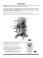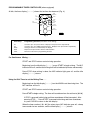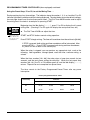
1
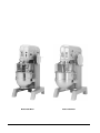
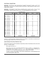
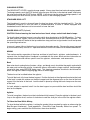
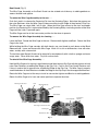
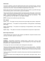
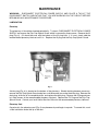
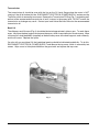
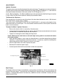
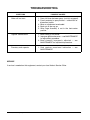
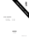
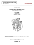
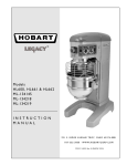
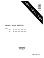
I
N
S
T
R
U
C
T
H600 MIXER
I
O
N
S
H600 & L800 MIXERS
MODELS
H600
ML - 104241, 104242, 104383, 104384
L800
ML - 104244, 104245, 104425, 104429
701 S. RIDGE AVENUE
TROY, OHIO 45374-0001
FORM 18812 Rev. B (12-99)
Model H600 Mixer
© HOBART CORPORATION, 1994
Model L800 Mixer
–2–
123456789012345678901234567890121234567890
123456789012345678901234567890121234567890
123456789012345678901234567890121234567890
123456789012345678901234567890121234567890
123456789012345678901234567890121234567890
123456789012345678901234567890121234567890
123456789012345678901234567890121234567890
123456789012345678901234567890121234567890
123456789012345678901234567890121234567890
123456789012345678901234567890121234567890
123456789012345678901234567890121234567890
123456789012345678901234567890121234567890
123456789012345678901234567890121234567890
123456789012345678901234567890121234567890
123456789012345678901234567890121234567890
123456789012345678901234567890121234567890
123456789012345678901234567890121234567890
123456789012345678901234567890121234567890
123456789012345678901234567890121234567890
123456789012345678901234567890121234567890
123456789012345678901234567890121234567890
123456789012345678901234567890121234567890
123456789012345678901234567890121234567890
1234567890123456789012345678901212345678901234567890123456789012123456789012
123456789012345678901234567890121234567890
1234567890123456789012345678901212345678901234567890123456789012123456789012
123456789012345678901234567890121234567890
1234567890123456789012345678901212345678901234567890123456789012123456789012
123456789012345678901234567890121234567890
1234567890123456789012345678901212345678901234567890123456789012123456789012
123456789012345678901234567890121234567890
1234567890123456789012345678901212345678901234567890123456789012123456789012
123456789012345678901234567890121234567890
1234567890123456789012345678901212345678901234567890123456789012123456789012
123456789012345678901234567890121234567890
1234567890123456789012345678901212345678901234567890123456789012123456789012
123456789012345678901234567890121234567890
1234567890123456789012345678901212345678901234567890123456789012123456789012
123456789012345678901234567890121234567890
1234567890123456789012345678901212345678901234567890123456789012123456789012
123456789012345678901234567890121234567890
1234567890123456789012345678901212345678901234567890123456789012123456789012
123456789012345678901234567890121234567890
1234567890123456789012345678901212345678901234567890123456789012123456789012
123456789012345678901234567890121234567890
1234567890123456789012345678901212345678901234567890123456789012123456789012
The H600 model
mixer is a heavy duty 60 quart mixer which features a 2 horsepower motor, a timer,
123456789012345678901234567890121234567890
1234567890123456789012345678901212345678901234567890123456789012123456789012
1234567890123456789012345678901212345678901234567890123456789012123456789012
1234567890123456789012345678901212345678901234567890123456789012123456789012
and a #12 attachment
hub as standard equipment. With the use of bowl adapters and special agitators,
1234567890123456789012345678901212345678901234567890123456789012123456789012
1234567890123456789012345678901212345678901234567890123456789012123456789012
30 or 40 quart
bowls
may
be used on the H600.
1234567890123456789012345678901212345678901234567890123456789012123456789012
1234567890123456789012345678901212345678901234567890123456789012123456789012
1234567890123456789012345678901212345678901234567890123456789012123456789012
1234567890123456789012345678901212345678901234567890123456789012123456789012
1234567890123456789012345678901212345678901234567890123456789012123456789012
The L800 model
mixer is a medium duty 80 quart mixer designed primarily for use in general kitchen
1234567890123456789012345678901212345678901234567890123456789012123456789012
1234567890123456789012345678901212345678901234567890123456789012123456789012
1234567890123456789012345678901212345678901234567890123456789012123456789012
applications.
This
mixer features a timer and #12 attachment hub as standard equipment and is
1234567890123456789012345678901212345678901234567890123456789012123456789012
powered by1234567890123456789012345678901212345678901234567890123456789012123456789012
a
2
horsepower
motor. With the use of bowl adapters and special agitators, 30, 40, or 60
1234567890123456789012345678901212345678901234567890123456789012123456789012
quart bowls may be used on the L800.
Installation, Operation, and Care of
H600 and L800 MIXERS
SAVE THESE INSTRUCTIONS
GENERAL
Bowl Guard is standard equipment on all H600 and L800 models.
Programmable Timer Controller is optional on H600 and L800 models.
These mixers can be ordered with deluxe finish, which includes a chrome plated transmission case,
base, bowl support, and pedestal.
A variety of attachments and accessories are available for all mixers. These are described in a
separate Use and Applications Handbook which is furnished with each mixer.
–3–
INSTALLATION
UNPACKING
Immediately after unpacking the mixer, check for possible shipping damage. If this machine is found
to be damaged after unpacking, save the packaging material and contact the carrier within 15 days of
delivery.
Prior to installation, test the electrical service to assure that it agrees with the specifications on the
machine data plate.
LOCATION
Place the mixer in its operating location. There should be adequate space around the mixer for the user
to operate the controls and install and remove bowls. The area above the mixer should allow the top
cover to be removed for routine maintenance and servicing.
Holes are provided in the base for permanent bolting to the floor, although this is not necessary in
normal installations. Four plastic plugs are supplied with the mixer to plug these holes if they are not
used.
Once located, the mixer must be leveled.
Remove the top cover screws and the top cover.
Place a level on the machined surface of the transmission case (Fig. 1) and slide shims under
the legs (base) of the mixer as required to level it front-to-back and side-to-side.
Do not replace the top cover until installation is completed.
Fig. 1
Check Lubrication Before Use
This mixer is shipped with oil in the transmission and planetary. Check oil levels before starting mixer.
Refer to LUBRICATION, pages 13 – 14, for applicable lubrication procedures.
–4–
ELECTRICAL CONNECTIONS
WARNING: ELECTRICAL AND GROUNDING CONNECTIONS MUST COMPLY WITH THE
APPLICABLE PORTION OF THE NATIONAL ELECTRICAL CODE AND/OR OTHER LOCAL
ELECTRICAL CODES.
WARNING: DISCONNECT ELECTRICAL POWER SUPPLY AND PLACE A TAG AT THE
DISCONNECT SWITCH INDICATING THAT YOU ARE WORKING ON THE CIRCUIT.
ELECTRICAL DATA
Model Volts / Hz / Ph
Rated
Amps
Circuit Size
(Amps)
Fuse Size *
(Amps)
60°C Copper
Wire Size
Circuit Size
(Amps)
Circuit Breaker **
(Amps)
60°C Copper
Wire Size
H600
115 / 60 / 1
19.0
25
25
10
30
30
10
H600
200 / 60 / 1
10.9
15
15
14
20
20
12
H600
230 / 60 / 1
9.5
15
15
14
15
15
14
H600
200 / 60 / 3
5.8
15
10
14
15
10
14
H600
230 / 60 / 3
5.0
15
6
14
15
10
14
H600
460 / 60 / 3
2.5
15
3
14
15
6
14
H600 ‡
200 / 60 / 1
14.3
20
20
12
20
20
12
H600 ‡
230 / 60 / 1
12.9
20
20
12
20
20
12
H600 ‡
200 / 60 / 3
9.2
15
15
14
20
20
12
H600 ‡
230 / 60 / 3
8.4
15
10
14
20
20
12
L800
200 / 60 / 1
12.7
20
20
12
20
20
12
L800
230 / 60 / 1
11.0
15
15
14
20
20
12
L800
200 / 60 / 3
6.5
15
10
14
15
15
14
L800
230 / 60 / 3
5.6
15
6
14
15
10
14
L800
460 / 60 / 3
2.8
15
3
14
15
6
14
L800 ‡
200 / 60 / 1
16.1
25
25
10
30
30
10
L800 ‡
230 / 60 / 1
14.4
20
20
12
25
25
10
L800 ‡
200 / 60 / 3
9.9
15
15
14
20
20
12
L800 ‡
230 / 60 / 3
9.0
15
15
14
20
20
12
‡ Power Bowl Lift
* Dual Element
Time-Delay Fuse
** Inverse Time
Circuit Breaker
Circuit Size (Minimum) & Fuse / Circuit Breaker Size (Maximum) compiled in accordance with the National Electrical Code (ANSI/NFPA 70), 1993 Edition.
A hole for 3⁄4" trade size conduit is located at the top of the pedestal. Make electrical connections per
the wiring diagram located on the inside of the Top Cover.
Check Rotation (Three-Phase Machines Only)
Three-phase machines must be connected so the planetary rotates in the direction of the arrow on the
Drip Cup. To check rotation:
Set the gear shift lever on 1.
Apply power to the mixer, set the Electro-Mechanical Timer on HOLD; or, if equipped with a
Programmable Timer Controller, set it on [ -- : -- ]. With the Bowl Support all the way up,
momentarily run the machine by pushing the START and then STOP buttons.
If rotation is incorrect, DISCONNECT ELECTRICAL POWER SUPPLY and interchange any two
of the incoming power supply leads.
–5–
OPERATION
WARNING: MOVING BEATER IN BOWL, KEEP HANDS, CLOTHING, AND UTENSILS OUT WHILE
IN OPERATION, DO NOT USE WITHOUT INTERLOCKED GUARD.
Every H600 and L800 mixer is equipped with either an Electro-Mechanical Timer Control (described
at the bottom of this page) or a Programmable Timer Controller (described on pages 7 – 9). Also,
become familiar with the other operating parts (Fig. 2) and their functions, which are referenced
throughout the OPERATION section (pages 6 – 12).
The Bowl Guard must be in position or the mixer will not operate. Refer to page 11.
If the Bowl Support is not all the way up, the mixer will not operate unless the START button is held
in.
Contols
Gear Shift Lever
Attachment Hub
Handwheel
Drip Cup
Apron
Bowl Guard
Bowl Scraper
Attachment (optional)
Agitator
Bowl Handle
Alignment Pin
Bowl Clamp
Bowl
Bowl Support
PL-40067-1
Fig. 2
ELECTRO-MECHANICAL TIMER CONTROLS (when equipped)
9
10 11
8
TIMER
12
13
7
The START button is used to start the mixer.
14
6
15
5
4
The STOP button is used to stop the mixer.
3
2
The TIMER is used in conjunction with the START
button for timed mixing operations and will stop the
mixer when a preset time has elapsed.
For non-timed mixing — Set the timer on HOLD
and use the STOP button to stop the mixer.
1 0
HOLD
START
STOP
BUTTON
STOP
Fig. 3
–6–
START
BUTTON
PL-51306
PROGRAMMABLE TIMER CONTROLLER (when equipped)
At Idle, the timer display [ – – : – – ] shows that no time has been set (Fig. 4).
P1
KEY
P2
KEY
M/C
INDICATOR
TIMER
CONTROL
KNOB
P1
1
P2
TIME
DISPLAY
2
3
4
TIME
M/C
SAVE
SAVE
KEY
CLEAR
CLEAR
KEY
START
BUTTON
START
STOP
BUTTON
STOP
PL-51307
Fig. 4
Timer Keys
Programming Function (if the mixer is not mixing).
P1
P2
Knob
Save
Clear
Contains up to four preset times. Displays each preset time sequentially.
Contains up to four additional preset times. Displays each preset time sequentially.
Changes the time as indicated by the display.
Replaces the preset time with the indicated time.
Returns to Idle from a programming function.
For Continuous Mixing . . .
START and STOP buttons control mixing operation.
Beginning from the Idle display [ – – : – – ], press START to begin mixing. The M/C
indicator will be lit, and the total mixing time will be indicated (minutes and seconds).
Press STOP when mixing is done; the M/C indicator light goes off; and the Idle
display [ – – : – – ] returns.
Using the Dial Timer to set the Mixing Time . . .
Beginning from the Idle display [ – – : – – ], turn the KNOB to set the mixing time. The
M/C indicator will be lit.
START and STOP buttons control mixing operation.
Press START to begin mixing: The timer will countdown from the set time to [00 : 00].
If STOP is pressed, both mixing and timer countdown will be interrupted. After
pressing STOP . . . Press START to resume both mixing and timer countdown;
or, press CLEAR to return to the Idle display.
When the timer reaches [ 00 : 00 ] the mixer stops; M/C indicator goes off; a beep
tone sounds for two seconds; and the Idle display [ – – : – – ] returns.
–7–
PROGRAMMABLE TIMER CONTROLLER (when equipped) continued
Using the Preset Keys, P1 or P2, to set the Mixing Time . . .
Each preset key has four time settings. The indicator above the number 1, 2, 3, or 4 and the P1 or P2
indicator light identify which preset time is being displayed. The chart below shows the default settings;
the next page shows how to revise these preset times. The Dial Timer KNOB can be used to adjust
the mixing time if the knob is turned prior to pressing START.
Beginning from the Idle display [ – – : – – ], press P1 or P2 to display the #1 preset
mixing time. ( Pressing P1 or P2 again will display the next preset time, etc.)
P1
-
P2
01:00
-1 -2 3- 4-
Indicators above P1
and 1 indicate the
first preset time
contained in P1.
☛ The Dial Timer KNOB can adjust the time.
START and STOP buttons control mixing operation.
Press START to begin mixing: The timer will countdown from the set time to [00 : 00].
If STOP is pressed, both mixing and timer countdown will be interrupted. After
pressing STOP . . . Press START to resume both mixing and timer countdown;
or, press CLEAR to return to the Idle display.
When the mixer is stopped, you may perform any appropriate task, such as the
following: Add ingredients, change speed, reset the timer, continue mixing, or
unload.
When the timer reaches [ 00 : 00 ] the mixer stops; a beep tone sounds for two
seconds; and the next preset mixing time displays. When the last preset time
reaches [ 00 : 00 ], the P1 or P2 indicator goes off; and the Idle display [ – – : – – ]
returns. Repeat from ☛ to complete four preset times.
The timer reverts to the Factory Programmed Preset Times after any power
interruption:
Factory Programmed Preset Times
Preset Key
Indicator
1
2
3
4
P1
01:00
02:00
10:00
00:00
P2
02:00
01:00
05:00
03:00
–8–
PROGRAMMABLE TIMER CONTROLLER (when equipped) continued
To Revise the Preset Mixing Times contained in P1 or P2 . . .
Each preset key has four preset time settings. The indicator above the number 1, 2, 3, or 4 and the
P1 or P2 indicator light identify which preset time is being displayed.
Beginning from the Idle display [ – – : – – ], press P1 or P2 to display the #1 preset
mixing time. ( Pressing P1 or P2 again will display the next preset time, etc.)
P1
-
P2
01:00
---1 2 3 4
☞ Turn the KNOB to change the time for the indicated preset.
• Press SAVE to retain the revised time and move to the next preset time.
Indicators above P1
and 1 indicate the
first preset time
contained in P1.
Repeat from ☞ for each preset time (1, 2, 3, and 4 contained in P1 or P2).
Pressing CLEAR will retain the saved times and return to the Idle display [– – : – –].
The timer reverts to the Factory Programmed Preset Times after any power
interruption:
Factory Programmed Preset Times
Preset Key
Indicator
1
2
3
4
P1
01:00
02:00
10:00
00:00
P2
02:00
01:00
05:00
03:00
–9–
CHANGING SPEEDS
The GEAR SHIFT LEVER is used to change speeds. Always stop the mixer before changing speeds.
To change speeds, push the STOP button, move the gear shift lever to the desired speed, and restart
the mixer by pushing the START button. NOTE: If you do not stop the mixer to change speeds, it will
automatically shut itself off and you will have to restart it after changing speeds.
STANDARD BOWL LIFT
The Handwheel is used to raise and lower the bowl on mixers with the standard bowl lift. Turn the
Handwheel clockwise to raise the bowl or counterclockwise to lower it. Mixers equipped with
Handwheel bowl lift device must be turned off to lower the bowl.
POWER BOWL LIFT (Optional)
CAUTION: Before lowering the bowl onto a bowl truck, always unlock both bowl clamps.
To raise the bowl and bowl support, move the switch lever clockwise to the RAISE position. To lower
the bowl and bowl support, move the switch lever counterclockwise to the LOWER position. An
overload slip clutch will ratchet at the top and bottom stop positions to signal end of travel and protect
the operating mechanism.
In case of a power failure, the bowl may be raised or lowered manually. Remove the apron (secured
by four thumb screws) and use a 1" open-end wrench to turn the lift screw hex in the desired direction.
MIXING
This section explains operation of the mixer and how to install bowls, agitators, and attachments. A
separate Use and Applications Handbook is provided with the mixer which contains information on
mixing procedures and outlines specific uses for agitators, attachments, and accessories.
Bowl
New mixer bowls and agitators (beaters, whips, and dough arms) should be thoroughly washed with
hot water and a mild soap solution, rinsed with either a mild soda or vinegar solution, and thoroughly
rinsed with clear water BEFORE being used. This cleaning procedure should also be followed for
bowls and agitators before whipping egg whites or whole eggs.
The bowl must be installed before the agitator.
To install the bowl, fully lower the bowl support. Position the bowl so the alignment bracket on the back
of the bowl is under the retainer on the bowl support and the alignment pins on the front of the bowl
support fit in the holes in the bowl. Lock the bowl in place by rotating the bowl clamps over the ears
of the bowl.
If a bowl adapter is required, install it on the bowl support as you would the bowl and then install the
bowl on the adapter.
Agitator
To install an agitator, the bowl must be installed and fully lowered. Place the agitator in the bowl, push
it up on the agitator shaft, and turn it clockwise to seat the shaft pin in the slot of the agitator shank.
To Raise the Bowl While Mixing
To raise the bowl while the agitator is mixing the product (when required by recipe or when using the
Bowl Scraper Attachment): Load ingredients. Close Wire Cage Assembly. Select Low speed. To
begin mixing, press and hold the Start button; then raise the bowl.
– 10 –
Bowl Guard (Fig. 5)
The Wire Cage Assembly on the Bowl Guard can be rotated out-of-the-way to add ingredients or
access the bowl and agitator.
To rotate the Wire Cage Assembly to the rear . . .
Push the Latch in to release the Centering Pin from the Centering Ramp. Note how the grooves on
the nylon Retainers allow the Wire Cage to ride around the circular Ridge of the planetary Drip Cup.
The Wire Cage can rotate 360°; left or right. When the Wire Cage returns to the front and center
position, the Centering Pin is captured and held by the Centering Ramp, restricting rotation of the Wire
Cage until the Latch is pressed again.
The Wire Cage must be in the front-center position for the mixer to operate.
To remove the Wire Cage Assembly for cleaning . . .
Lower the Bowl. Rotate the Wire Cage to the rear. Remove both Agitator and Bowl. Return the Wire
Cage to the front.
While holding the Wire Cage securely with both hands, use your thumb to push down on the Black
Release Knob. Lower and remove the Wire Cage. Wash it in a sink or dishwasher; rinse with clear
water; and dry with a clean cloth.
The stainless steel Splash Guard can be wiped-off or washed easily with a cloth or sponge and warm
soapy water. Rinse with clear water. Dry with a clean cloth.
To reinstall the Wire Cage Assembly . . .
Hold the Wire Cage so its top ring is positioned around the planetary Drip Cup with the grooves in both
nylon Rear Retainers straddling the Ridge on the Drip Cup. Push-in the Front-Center Retainer until
it stays in and so that its grooves also straddle the Ridge on the Drip Cup. The Wire Cage is properly
assembled when all three Retainers straddle the Ridge on the Drip Cup in the three opposed locations.
Rotate the Wire Cage out-of-the-way to install or remove the Agitator and Bowl or to add ingredients.
Return the Wire Cage to its front and center position to operate the mixer.
Wire Cage Rotated Left
Latch
Ridge On Drip Cup
Rear Retainer
Splash Guard
Centering Ramp
Front-Center
Retainer
Wire Cage Front-Center Position
Centering Pin
Black Release Knob
PL-40071-1
Fig. 5
– 11 –
Attachments
To install an attachment, loosen the attachment hub thumb screw and remove the plug. Insert the
attachment into the attachment hub, making certain that the square shank of the attachment is in the
square driver of the mixer. Secure the attachment by tightening the thumb screw.
Move the gear shift lever to the desired speed. With the bowl support all the way up and the wire cage
in the front-center position, start the mixer to operate the attachment.
The meat and food chopper attachment should be operated in second or third speed. If material in the
cylinder stalls the mixer, push the STOP button at once. DO NOT attempt to restart the mixer in a lower
speed — remove the adjusting ring, knife, plate, and worm and clear any obstruction. THIS
ATTACHMENT MUST NOT BE USED TO CHOP BREAD CRUMBS.
NOTE: Attachment hub should not be used while mixing.
Mixer Speeds
Speed 1 (Low) — This speed is for heavy mixtures such as pizza dough, heavy batters, and potatoes.
Speed 2 (Medium-low) — This speed is for mixing cake batters, mashing potatoes, and developing
bread dough.
Speed 3 (Medium-high) — This speed is for incorporating air into light batches, as well as finishing
whipped items.
Speed 4 (High) — This speed is for maximum and accelerated air incorporation into light batches.
Bowl Scraper Attachment
The Mixer Bowl Scraper Attachment (when ordered) is provided with a separate instruction manual
covering its installation, operation, use and care.
CLEANING
WARNING: DISCONNECT ELECTRICAL POWER SUPPLY AND PLACE A TAG AT THE
DISCONNECT SWITCH INDICATING THAT YOU ARE WORKING ON THE CIRCUIT BEFORE
BEGINNING ANY CLEANING PROCEDURE.
A flat scraper and a brush are furnished to aid in cleaning bowls and agitators.
The mixer should be thoroughly cleaned daily. DO NOT use a hose to clean the mixer — it should be
washed with a clean damp cloth. The base allows ample room for cleaning under the mixer. The apron
may be removed by loosening the thumb screws. Behind this apron is an access cover which may be
removed for cleaning.
The Drip Cup-Splash Guard (which is secured by three screws) should be removed periodically and
wiped clean.
For cleaning the Bowl Guard (including both Wire Cage Assembly and Splash Guard), refer to
page 11.
– 12 –
MAINTENANCE
WARNING: DISCONNECT ELECTRICAL POWER SUPPLY AND PLACE A TAG AT THE
DISCONNECT SWITCH INDICATING THAT YOU ARE WORKING ON THE CIRCUIT BEFORE
BEGINNING ANY MAINTENANCE PROCEDURE.
LUBRICATION
Planetary
The planetary oil should be checked periodically. To check, DISCONNECT ELECTRICAL POWER
SUPPLY and remove the Drip Cup-Splash Guard, which is secured by three screws. Remove the fill
plug (Fig. 6). Oil should be even with the bottom of the fill plug hole. If it is not, slowly add the
recommended planetary lubricant until it is. Replace the fill plug and the Drip Cup-Splash Guard.
Fig. 6
A drain plug (Fig. 6) is located on the bottom of the planetary. Should draining become necessary,
remove the Drip Cup-Splash Guard and place a suitable catch pan under the drain plug. Remove the
drain plug, allow the oil to completely drain, and replace the drain plug. Remove the fill plug and pour
in 6 fluid ounces of the recommended planetary lubricant. Replace the Fill Plug and the Drip CupSplash Guard. Contact your local Hobart Service Office for the recommended planetary lubricant.
Planetary Seal
Occasionally, the planetary seal (Fig. 6) may become dry and begin to squeak. To correct this, work
a little lubrication under the lip of the seal.
– 13 –
Transmission
The transmission oil should be even with the line on the Oil Level Gauge when the motor is NOT
running. If the oil falls below this line, DISCONNECT ELECTRICAL POWER SUPPLY and remove the
Top Cover, which is secured by two screws. Remove the Transmission Fill Plug (Fig. 7) and add a small
amount of the recommended transmission oil until it returns to the proper level. DO NOT overfill the
transmission as leakage may result. Contact your local Hobart Service Office for the recommended
transmission oil.
Bowl Lift
The slideways and lift screw (Fig. 6) should be lubricated approximately twice a year. To reach these
areas, fully lower the bowl support and remove the apron, which is secured by four thumb screws. Wipe
a thin coat of Lubriplate 630AA (supplied) on the bowl clamp area of the bowl supports, each slideway,
and the lift screw. Replace the apron.
On units with a manual bowl lift, the handwheel gearing should be lubricated periodically. To do this,
DISCONNECT ELECTRICAL POWER SUPPLY and remove the top cover, which is secured by two
screws. Wipe a coat of Lubriplate 630AA on the gear teeth and replace the top cover.
Fig. 7
– 14 –
ADJUSTMENTS
Agitator Clearance
The agitator clearance should be checked with each bowl change. The agitator must not touch the bowl
and the maximum clearance between the bottom of the bowl and the B Flat Beater is 1 ⁄ 8 "; the maximum
clearance between the bottom of the bowl and the E or ED Dough Arm is 5⁄16".
Install a Bowl and Agitator. If the Bowl and Beater come into contact before the Bowl Support reaches
its stop, adjust the Stop Screw upwards following the procedure below.
To Measure the Clearance . . .
Pour enough flour in the bowl to cover the bottom of the bowl where the beater travels. With the bowl
fully raised, briefly run the mixer in speed 1.
Turn off the mixer, DISCONNECT ELECTRICAL POWER SUPPLY, and measure the depth of flour
where the beater has traced a path. This measurement should be taken at several points around the
bowl to assure accuracy.
To Adjust the Bowl / Agitator Clearance . . .
•
Remove the Apron (which is secured by 4 thumbscrews).
•
Loosen the bottom Locking Nut (Fig. 8), and turn the Stop Screw counterclockwise to increase
the clearance or clockwise to decrease the clearance.
•
Tighten the Locking Nut while holding the Stop Screw.
Caution: Make sure the switch button on the bowl height sensing switch is never below the bottom
of the nylon actuator.
•
When the Bowl Support is fully raised, the Switch Button on the Bowl Height Sensing Switch
should be 1⁄8" above the bottom of the Nylon Actuator. If necessary, adjust the Locking Nuts
above and below the Nylon Actuator to move it up or down.
•
After the adjustments are made, replace the Apron.
•
Reconnect the electrical power supply.
•
Carefully operate the bowl lift several times to check the adjustment.
Switch Button
Stop Screw
Bowl Height Sensing Switch
Locking Nuts
Bottom Locking Nut
Nylon Actuator
PL-40081-1
Fig. 8
Bowl Clamps
The height of the bowl clamp is controlled by a spring washer and lock nut, which are located on the
bottom of the bowl support. Turning the lock nut clockwise will loosen the clamp, counterclockwise will
tighten it. If repeated adjustments are necessary, additional service is indicated. Contact your local
Hobart Service Office.
– 15 –
TROUBLESHOOTING
SYMPTOMS
POSSIBLE CAUSES
Mixer will not start.
1. Gear shift lever between gears (not fully engaged).
2. Circuit protector in open position — check fuse or
disconnect switch.
3. Mixer or attachment overloaded.
4. Bowl not all the way up.
5. Wire Cage Assembly is not in the front-center
position.
Agitator touches bowl.
1. Bowl clamp(s) not closed.
2. Improper agitator clearance — see MAINTENANCE
for adjustment procedure.
3. Bowl clamp(s) improperly adjusted — see
MAINTENANCE for adjustment procedure.
Planetary seal squeaks.
1. Seal requires occasional lubrication — see
MAINTENANCE.
SERVICE
If service is needed on this equipment, contact your local Hobart Service Office.
FORM 18812 Rev. B (12-99)
– 16 –
PRINTED IN U.S.A.