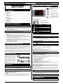
1
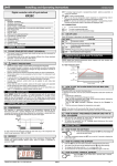
OWZA
FROZEN FOOD CASE
Installation & Operation Handbook
Table of Contents
Energy Data & Dimensions ...........................2-3
General Information ......................................... 4
Installation......................................................5-6
Refrigeration Piping ......................................... 7
Plumbing ........................................................... 8
Electrical Connections ..................................... 9
Air Flow, Defrost & Temp Control.................. 10
Use & Maintenance ........................................ 11
Parts Ordering ................................................ 12
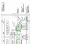
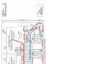
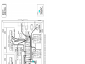
Appendix A: Domestic Wiring Diagrams
Appendix B: Export Wiring Diagrams
Appendix C: Controller Information
Appendix D: User Set Points
P074749F
Rev. 2 07/09
ii
Important
At Hill PHOENIX , the safety of our customers and employees, as well as the ongoing performance of our products, are top
®
priorities. To that end, we include important warning messages in all Hill PHOENIX installation and operation handbooks, accompanied by an alert symbol paired with the word "DANGER", "WARNING", or "CAUTION".
All warning messages will inform you of what the potential hazard is; how to reduce the risk of death, injury, or damage; and
what may happen if the instructions are not properly followed.
▲ DANGER
"DANGER" indicates an immediate threat of death or
serious injury if all instructions are not followed carefully.
▲W A R N I N G
"WARNING" indicates a possible threat of death or serious injury if all instructions are not followed carefully.
▲C A U T I O N
"CAUTION" indicates that failure to properly follow
instructions may result in case damage.
iii
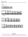
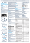
ENERGY DATA
OWZA
System Requirements
Model
Volts
Phase
Hz
Plug
Style
Cord
Length
OWZA - 8'
230
1
60
L14-30P
10'
1 For export cases, a NEMA L6-30 electrical plug is used.
Condensing Unit Data (2 units/case)
2
Condenser
Fans
3
Model
Volts
Phase
Frequency
(Hz)
HP
RLA
(amps)
LRA
(amps)
Refrig.
Amps4
Watts
Lbs. of
Refrig.
OWZA - 8’ (med temp)
208-230
1
60
3/4
7.7
37.0
R404A
1.4
70
5
OWZA - 8’ (low temp)
208-230
1
60
1-1/2
15.4
74.0
R404A
2.8
140
10
2 RLA = Running Load Amps
3 LRA = Locked Rotor Amps
4 Amps shown are included in RLA rating.
Guidelines & Control Settings
Model
24hr Energy
Usage
(kWh)
Suction Pressure
@ Case Outlet
(psig)
Superheat Set
Point @ bulb
(Fo)
Discharge
Air
(Fo)
Return
Air
(Fo)
Discharge
5
Air Velocity
(FPM)
OWZA - 8’ (med temp)
9.3
60.8
6-8
25.7
33.3
200
OWZA - 8’ (low temp)
13.5
16.3
6-8
-17
3
200
5 Average discharge air velocity at peak of defrost.
Defrost Controls
6
Electric Defrost
7
Timed Off Defrost
Hot Gas Defrost
Model
Defrosts
Per Day
Fail-Safe
(min)
Termination
Temp (°F)
Fail-Safe
(min)
Termination
Temp (°F)
Fail-Safe
(min)
OWZA - 8'
2
50
46
50
46
---
6 Low temperature defrost
7 Medium temperature defrost
8 "- - -" not an option on this case model.
All measurements are taken per ARI 1200 - 2002 specifications.
COMPONENT
2
8
Reverse Air Defrost
Termination
Temp (°F)
Fail-Safe
(min)
Termination
Temp (°F)
---
---
---
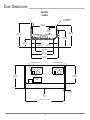
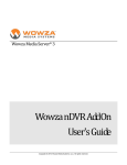
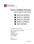
CASE DIMENSIONS
MODEL
OWZA
6" THERMOPANE
GLASS FRONT
43-1/4 in
[109.9 cm]
12-7/8 in
[32.7 cm]
38-1/2 in
[97.8 cm]
43 in
[109.2 cm]
COIL
PLENUM
29-5/8 in
[75.3 cm]
13-1/8 in
[33.3 cm]
8-7/8 in
[22.6 cm]
7-7/8 in
[20.0 cm]
33-11/16 in
[85.6 cm]
42-9/16 in
[108.1 cm]
51-5/16 in
[130.3 cm]
CONDENSING UNIT
CONDENSING UNIT
53-1/4 in
[135.3 cm]
42-5/8 in
[108.2 cm]
DRAIN
PAN
JUNCTION
BOX
1-1/2 in
[3.8 cm]
C
L
96 in [243.8 cm] {8’ CASE}
3
GENERAL INFORMATION
Thank you for choosing Hill PHOENIX for your food merchandising needs.
This handbook contains important technical information and will assist you with the installation and operation of your new Hill PHOENIX display cases. By closely following
the instructions, you can expect peak performance; attractive fits and finish; and long case life.
We are always interested in your suggestions for improvements (e.g. case design, technical documents, etc.). Please feel free to
contact our Marketing Services group at the toll-free number listed below. Thank you for choosing Hill PHOENIX, and we wish
you the very best in outstanding food merchandising.
*
*
*
CASE DESCRIPTION
LOST/MISSING ITEMS
This manual specifically covers the OWZA frozen food merchandiser.
Equipment has been carefully inspected to insure the highest
level of quality. Any claim for lost/missing items must be
made to Hill PHOENIX within 48 hours of receipt of the
equipment.
STORE CONDITIONS
Hill PHOENIX cases are designed to operate in an air-conditioned store that maintains a 75°F (24°C) store temperature and
55% (max) relative humidity (CRMA conditions). Case operation will be adversely affected by exposure to excessively high
ambient temperatures and/or humidity.
TECHNICAL SUPPORT
For technical questions regarding display cases, please contact
our Case Division Customer Service Department at the tollfree number listed below. For questions regarding our refrigeration systems or electrical distribution centers, please contact
our Systems Division Customer Service Department at 1-770388-0706.
RECEIVING CASES
Examine fixtures carefully for shipping damage and shortages.
For information on shortages, contact the Service Parts
Department at the toll-free number listed below.
CONTACTING THE FACTORY
If you need to contact Hill PHOENIX regarding a specific fixture, be certain that you have both the case model number and
serial number – this information is on the serial plate located
on the lower rear baffle of the case. When you have this information, call the toll-free number below and ask for a Service
Parts Representative.
CASE DAMAGE
Claims for obvious damage must be 1) noted on either the
freight bill or the express receipt and 2) signed by the carrier's
agent; otherwise, the carrier may refuse the claim. If damage
becomes apparent after the equipment is unpacked, retain all
packing materials and submit a written request to the carrier for
inspection within 14 days of receipt of the equipment.
HILL PHOENIX
1925 Ruffin Mill Rd.
Colonial Heights, VA 23834
Tel: 1-800-283-1109 / Fax: 804-526-7450
Web site: www.hillphoenix.com
4
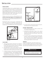
INSTALLATION
MOVING CASES
Hill PHOENIX display cases are generally shipped to stores
with casters installed on the base frame. The casters make the
job of moving cases easier for everyone involved in the shipping and installation process, as well as reducing the chance of
damage from raising and lowering cases with ”J” bars to place
them on dollies, skates or rollers. In most situations, one or two
persons can easily move the case into position.
FRONT
KICK PLATE
SCREW
CONNECTOR
TAB
When the cases arrive at the store, simply roll them on to the
store floor to the proper staging area. Occasionally, cases are
shipped with skid boards attached to help with stabilization. In
these instances, the casters should be attached after the case is
removed from the truck.
SLOT
Fig. 2 Attaching the front and end kick plates
Removing the casters is an easy process. Simply flatten and
remove the cotter pins that are holding the casters in place (see
Fig. 1). Then lift the case with a “J” bar and slide the caster
assemblies out. The dismantled casters can now be discarded.
4. Locate the position of the base frame and spot properly leveled shim packs at the appropriate locations.
LINE-UP & INSTALLATION
1. Remove anything from the cases that may interfere with
case joining (eg. shipping braces).
2. Roll the first case into position. Using a “J” bar , raise the
end of the case (under cross support), remove the casters,
and place the base frame on the shim packs. Repeat on the
other end of the case.
3. Once the base frame is properly placed on the shim packs,
check the vertical level by placing a bubble level plumb to
the rear edge of the case; then add/remove shim levels as
needed. To check the horizontal level, repeat this process
after placing the bubble level on the rear sill.
COTTER PIN
Fig. 1 Cotter pin attaches the caster
to the case
TRIM OUT
FLOOR PREP
Attach the front kick plate to the retainer using the screws
1. Ask the general contractor if there have been changes in provided. To attach the end kick plates, slide them under the
the building dimensions since the print you are using was
issued. Also, ask for the points of reference from which
you should take dimensions to locate the cases.
case ends, thread the hanging connector tabs into the provided
slots, then drop the kick plates down into place (see Fig. 2).
2. Using chalk lines or a laser transit, mark the floor where
the cases are to be located for the entire lineup. The lines
should coincide with the outside edges of the base frame.
▲W A R N I N G
3. Leveling is necessary to ensure proper case alignment and
Be certain that your hands and feet are out of the way
before lowering the case after the removal of the casters. Failure to do so may result in serious injury.
to avoid potential damage. Locate the highest point on the
positioning line as a reference for determining the proper
height of the shim-pack levelers. A laser transit is recommended for precision and requires just one person.
5
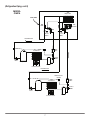
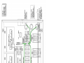
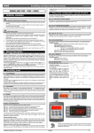
REFRIGERATION PIPING
Refrigeration components for OWZA cases are easily accessible in the tank and beneath the case.
The diagram on page 7 illustrates all of the refrigeration
components in the case – the box-shaped dotted line indicates
those components that are located within the case tank.
The expansion valve and suction line 1/4” access valve are
both located on the front-left side of the tank and are accessible without lifting the fan plenum. These components may
be reached by lifting only the left-hand deck pan which minimizes the need to remove product.
*
Basic definitions of these components are listed below.
*
*
Filter Drier
A device installed on the liquid line of a refrigeration system
that removes water and other impurities from the refrigerant in
the lines during initial start-up.
Access Valve
Access port on the evaporator that allows service personnel to
check system pressure.
Accumulator
A device installed on the suction line that is used to boil off
small amounts of liquid refrigerant so liquid does not reach the
compressor.
Receiver
The component in a refrigeration system that stores liquid refrigerant that is not being used by the system in low load conditions or when the system is shut down.
Compressor
An electrically driven piston pump that pumps vapor refrigerant from a low pressure level to a higher pressure level.
Service Valve
A manually operated valve in the refrigeration system that is
used for various service operations such as isolating the high or
low sides of the system.
Condenser
The component in a refrigeration system that transfers the heat
that was absorbed by the refrigerant in the evaporator and the
heat of compression from the system by condensing the refrigerant.
Suction Line Solenoid
A device that prevents liquid from entering the compressor.
Thermostatic Expansion Valve (TXV)
A valve that controls the flow of liquid refrigerant to the evaporator coil and also separates the high pressure side of the system
from low pressure side of the system.
Condenser Fan
Fan that forces air through the air cooled condenser to aid heat
transfer.
Thermostatic Expansion Valve (TXV) Bulb
A bulb that is attached to the suction line of the evaporator that
controls the TXV. Inside the bulb is a charge that reacts to
temperature and regulates the flow of refrigerant through the
expansion valve.
Dual Pressure Control
A device that protects the compressor from low charge and high
pressure.
Split Evaporator
The component of the refrigeration system that absorbs heat
from the air by boiling liquid refrigerant to vapor.
Evaporator Fans
Fans that circulate air through the case and force air through the
evaporator to aid heat transfer.
6
(Refrigeration Piping, cont'd)
MODEL
OWZA
Split
Evaporator
TANK AREA
TVX
Bulb
Fan
Plenum
TVX
TVX
1/4"
Access
Valve
1/4"
Access
Valve
Flow Direction
Filter
Drier
Condenser
Service
Valve
Service
Valve
Compressor
Receiver
Condenser Fan
Flow Direction
Dual Pressure
Control
Filter
Drier
Condenser
Service
Valve
Service
Valve
Compressor
Receiver
Condenser Fan
7
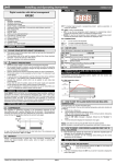
PLUMBING
The “P” trap assembly – attached to the case at the factory so
no assembly is required – directs the case drainage to the drain
pan.
outlet is specially molded with PVC material and the “P” trap
is constructed of PVC. Care should be given to make certain
that all connections are water tight and are sealed with appropriate PVC primer and PVC cement.
The case drain is located front-and-center in the case for convenient access – simply remove the front kick plate. Should
any future maintenance issues arise, it is important to note the
Be certain that the case is properly leveled to ensure proper
drainage.
MODEL
OWZA
"P"
TRAP
DRAIN
VALVE
EVAPORATOR
PAN
8
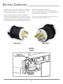
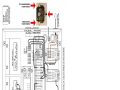
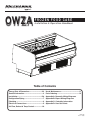
ELECTRICAL CONNECTIONS
The OWZA comes pre-wired with a NEMA L14-30P twistlock plug (250 volt, 4-prong). For export models, a NEMA
L6-30 twist-lock plug (250 volt, 3-prong) is used.
tion utilizes on the right-hand controller.
The case is turned ON/OFF via an electric breaker that is
located on the electrical junction box, in the left-hand side of
the case behind the front kick plate.
Dual Dixell XR03CX digital controllers are provided for
case operation and programming. The controllers are located
inside the electrical junction box and are utilized according to
your temperature preference: low-temperature operation only
uses the left-hand controller while medium-temperature opera-
NOTE: Dixell controller information and user setpoints can
be found in this manual's Appendix section.
NEMA L6-30 PLUG
(TWIST LOCK)
NEMA L14-30P PLUG
(TWIST LOCK)
MODEL
OWZA
DIGITAL
CONTROLLERS
BREAKER
SWITCH
9
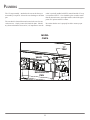
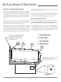
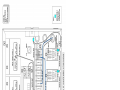
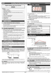
AIR FLOW, DEFROST & TEMP CONTROL
DEFROST & TEMPERATURE CONTROLS
OWZA cases are equipped with both Electric (low-temp) and
Timed-Off (medium-temp) defrost and can be run in either lowor medium-temperature defrost modes. Switching between the
two different temperature modes is easily done by using a special key switch located on the left-bottom-front of the case (see
Fig. 3).
ing the front kick plate and lower front panel, see the trim out
section of this manual on page 5.
It is important to consult the control setting guidelines shown
on page 2 before setting the defrost schedule. Further adjustments may be required depending on store conditions.
AIR FLOW & PRODUCT LOAD
The rear baffle (see diagram below) contains the sensor bulb
and probe for electric defrost termination; the sensor bulb for
temperature control; and the discharge air probe.
Cases have been designed to provide maximum product capacity within the refrigerated air envelope. Please keep products
within the load limit line shown on the diagram below.
The defrost termination control thermostat and the temperature
control thermostat are located in the junction box underneath
the case on the bottom-left side (see diagram below). To access the thermostats, you must first remove the front kick plate,
then remove the junction box cover. For instructions on remov-
It is important that you do not overload the food product display
so that it impinges on the air flow pattern. Overloading will
cause malfunction and the loss of proper temperature levels,
particularly when discharge and return air sections are covered.
1. DISCHARGE AIR
Electric defrost termination sensor bulb
Electric defrost termination probe
2. LOAD LIMIT
Temperature control sensor bulb
Discharge air probe
3. AIR CURTAIN
1
2
3
4. RETURN AIR
4
Defrost termination control thermostat
Temperature control thermostat
JUNCTION
BOX
LOW
TEM
P
MED TEMP
Fig. 3 Low/Med Temp
keyed switch
10
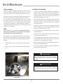
USE & MAINTENANCE
CASE CLEANING
Cases are designed to facilitate cleaning. All surfaces pitch to
a deep-drawn drain trough that angles toward the front-center
of the case where the waste outlet is located for easy access.
The coil is covered to prevent waste fluids from entering, but
it is easily accessible for cleaning: simply remove the two
coil-cover fasteners, then lift and remove the coil cover. With
the coil cover removed, be certain to exercise extreme caution
when working in the case - the coil has many sharp edges that
can result in serious injuries. When cleaning is complete, be
certain that both the plenum and coil cover are properly closed
in order to avoid air leaks.
FANS
The fan blades are 8” in diameter. It is important that the
blade pitch be maintained as specified. Do not attempt a
field modification by altering the blades.
Fan motors may be changed with an easy two-step process
that does not require lifting up the plenum, thereby, avoiding
the necessity to unload the entire product display to make a
change:
1. Unplug the fan motor, easily accessible outside the plenum.
2. Remove the six fasteners, then lift out the entire fan bas-
CLEANING PROCEDURES
•
A periodic cleaning schedule should be established to
maintain proper sanitation, insure maximum operating efficiency, and avoid the corrosive action of food fluids on
metal parts that are left on for long periods of time. We
recommend cleaning once a week.
•
To avoid shock hazard, be sure all electrical power is turned
off before cleaning. In some installations, more than one
disconnect switch may have to be turned off to completely
de-energize the case.
•
Check waste outlet to insure it is not clogged before starting the cleaning process and avoid introducing water faster
than the case drain can carry it away.
•
Avoid spraying cleaning solutions directly on fans or electrical connections.
•
Allow cases to be turned off long enough to clean any frost
or ice from coil and flue areas.
•
Use mild detergent and warm water. When necessary, water and baking soda solution will help remove case odors.
Avoid abrasive scouring powders or pads.
•
Remove front panels and clean underneath the case with a
broom and a long handled mop.
•
Use warm water and a disinfecting cleaning solution when
cleaning underneath the cases.
ket.
▲ DANGER
SHOCK HAZARD
Always disconnect power to case when servicing or
cleaning. Failure to do so may result in serious injury
or death.
COVER
SCREW
▲W A R N I N G
FAN
BASKET
FAN
MOTOR
PLUG
Exercise extreme caution when working in a case with
the coil cover removed. The coil contains many sharp
edges that can result in severe cuts to the hands and
arms.
FAN ASSEMBLY
11
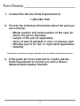
PARTS ORDERING
1. Contact the Service Parts Department at:
1-800-283-1109
2. Provide the following information about the part you
are ordering:
• Model number and serial number of the case for
which the part is intended.
• Length of the part (if applicable).
• Color of part (if painted) or color of polymer part.
• Whether part is for left- or right-hand application.
• Quantity
*Serial plate is located on the right-hand side of the rear baffle, inside the product area.
3. If the parts are to be returned for credit, ask the
Parts Department to furnish you with a Return
Material Authorization Number.
12
APPENDIX A:
DOMESTIC WIRING DIAGRAM
APPENDIX B:
EXPORT WIRING DIAGRAM
APPENDIX C:
CONTROLLER INFORMATION
dIXEL
Operating Manual
DIGITAL CONTROLLER
1592020130
6. FRONT PANEL COMMANDS
XR03CX – XR04CX
To display target set point, in
programming mode it selects a
parameter or confirm an
operation
1. CONTENTS
1.
2.
3.
4.
5.
6.
7.
8.
9.
10.
11.
12.
13.
14.
15.
Contents __________________________________________________________________________ 1
General warnings ___________________________________________________________________ 1
General description __________________________________________________________________ 1
Regulation_________________________________________________________________________ 1
Defrost ___________________________________________________________________________ 1
Front panel commands _______________________________________________________________ 1
Parameters ________________________________________________________________________ 1
Digital inputs _______________________________________________________________________ 2
Installation and mounting _____________________________________________________________ 2
Electrical connections ________________________________________________________________ 2
How to use the hot key _______________________________________________________________ 2
Alarm signalling_____________________________________________________________________ 2
Technical data______________________________________________________________________ 2
Connections _______________________________________________________________________ 3
Default setting values ________________________________________________________________ 3
2. GENERAL WARNINGS
To start a manual defrost
AUX
KEYS COMBINATION
+
LED
PLEASE READ BEFORE USING THIS MANUAL
1. This manual is part of the product and should be kept near the instrument for easy and quick
reference.
2. The instrument shall not be used for purposes different from those described hereunder. It
cannot be used as a safety device.
3. Check the application limits before proceeding.
SAFETY PRECAUTIONS
•
Check the supply voltage is correct before connecting the instrument.
•
Do not expose to water or moisture: use the controller only within the operating limits avoiding
sudden temperature changes with high atmospheric humidity to prevent formation of
condensation
•
Warning: disconnect all electrical connections before any kind of maintenance.
•
Fit the probe where it is not accessible by the End User. The instrument must not be opened.
•
In case of failure or faulty operation send the instrument back to the distributor or to “Dixell
S.p.A.” (see address) with a detailed description of the fault.
•
Consider the maximum current which can be applied to each relay (see Technical Data).
•
Ensure that the wires for probes, loads and the power supply are separated and far enough from
each other, without crossing or intertwining.
•
In case of applications in industrial environments, the use of mains filters (our mod. FT1) in
parallel with inductive loads could be useful.
3. GENERAL DESCRIPTION
To lock or unlock the keyboard
+
+
To enter in programming mode
To return to room temperature display
MODO
On
Flashing
On
Flashing
On
Flashing
On
Flashing
SIGNIFICATO
Compressore enabled
Anti short cycle delay enabled (AC parameter)
Defrost in progress
Dripping in progress
Measurement unit
Programming mode
Measurement unit
Programming mode
HOW TO SEE THE SET POINT
1.
2.
Push and immediately release the SET key, the set point will be showed;
Push and immediately release the SET key or wait about 5s to return to normal visualisation.
HOW TO CHANGE THE SETPOINT
1.
2.
3.
4.
Push the SET key for more than 2 seconds to change the Set point value;
The value of the set point will be displayed and the “°C” or “°F” LED starts blinking;
To change the Set value push the o or n arrows within 10s.
To memorise the new set point value push the SET key again or wait 10s.
HOW TO START A MANUAL DEFROST
Push the DEF
key for more than 2 seconds and a manual defrost will start
HOW TO CHANGE A PARAMETER VALUE
The XR03CX, in 32×74x50mm short format, is microprocessor based controller suitable for applications on
normal temperature refrigerating units. It provides two relay output: one for compressor and the other one for
alarm signalling or as auxiliary output. It provides an NTC probe input and a digital input for alarm signalling,
for switching the auxiliary output or for start defrost. The instrument is fully configurable through special
parameters that can be easily programmed through the keyboard or the by HOTKEY.
The XR04CX, in 32×74x50mm short format, is microprocessor based controller suitable for applications on
normal or low temperature refrigerating units. It provides two relay output: one for compressor and the other
one for defrost. It provides two NTC probe inputs, one for room temperature and other one to control defrost
termination. The instrument is fully configurable through special parameters that can be easily programmed
through the keyboard or the by HOTKEY.
4. REGULATION
The regulation is performed according to
the temperature measured by the
thermostat probe with a positive
differential from the set point: if the
temperature increases and reaches set
point plus differential the compressor is
started and then turned off when the
temperature reaches the set point value
again.
In case of fault in the thermostat probe the start and stop of the compressor are timed through
parameters “Cy” and “Cn”.
5. DEFROST
XR03CX
Defrost is performed through a simple stop of the compressor. Parameter “id” controls the interval
between defrost cycles, while its length is controlled by parameter “Md”.
XR04CX
Two defrost modes are available through the “td” parameter:
• td=EL → defrost through electrical heater (compressor OFF)
• td=in → hot gas defrost (compressor ON).
Other parameters are used to control the interval between defrost cycles (id) ), its maximum length
(Md) and two defrost modes: timed or controlled by the evaporator’s probe. At the end of defrost
dripping time is started, its length is set in the dt parameter. With dt=0 the dripping time is disabled.
To change the parameter’s value operate as follows:
keys for 3s (“°C” or “°F” LED starts
1. Enter the Programming mode by pressing the SET+
blinking).
2. Select the required parameter. Press the “SET” key to display its value
or
to change its value.
3. Use
4. Press “SET” to store the new value and move to the following parameter.
or wait 15s without pressing a key.
To exit: Press SET+
NOTE: the set value is stored even when the procedure is exited by waiting the time-out to expire.
HIDDEN MENU
The hidden menu includes all the parameters of the instrument.
HOW TO ENTER THE HIDDEN MENU
keys for 3s (“°C” or “°F” LED starts
1. Enter the Programming mode by pressing the SET+
blinking).
keys for more than 7s. The L2 label will be
2. Released the keys, then push again the SET+
displayed immediately followed from the Hy parameter.
NOW YOU ARE IN THE HIDDEN MENU.
3. Select the required parameter.
4. Press the “SET” key to display its value
or
to change its value.
5. Use
6. Press “SET” to store the new value and move to the following parameter.
or wait 15s without pressing a key.
To exit: Press SET+
NOTE1: if none parameter is present in L1, after 3s the “nP” message is displayed. Keep the keys
pushed till the L2 message is displayed.
NOTE2: the set value is stored even when the procedure is exited by waiting the time-out to expire.
HOW TO MOVE A PARAMETER FROM THE HIDDEN MENU TO THE FIRST
LEVEL AND VICEVERSA.
Each parameter present in the HIDDEN MENU can be removed or put into “THE FIRST LEVEL” (user
level) by pressing SET+ . In HIDDEN MENU when a parameter is present in First Level the decimal
point is on.
TO LOCK THE KEYBOARD
•
•
Keep pressed for more than 3s the
and
keys.
The “OF” message will be displayed and the keyboard will be locked. If a key is pressed more
than 3s the “OF” message will be displayed.
TO UNLOCK THE KEYBOARD
Keep pressed together for more than 3s the
7. PARAMETERS
REGULATION
1592020130 XR03_04CX GB 16.01.07.doc
In programming mode it
browses the parameter codes
or increases the displayed
value
In programming mode it
browses the parameter codes
or decreases the displayed
value
XR03CX – XR04CX
and
keys till the “on” message will be displayed.
dIXEL
Operating Manual
Hy Differential: (0,1°C ÷ 25°C) Intervention differential for set point. Compressor Cut IN is SET
POINT + differential (Hy). Compressor Cut OUT is when the temperature reaches the set point.
LS Minimum SET POINT: (-55°C÷SET/-58°F÷SET): Sets the minimum value for the set point..
US Maximum SET POINT: (SET÷99°C/ SET÷99°F). Set the maximum value for set point.
ot First probe calibration: (-9.9÷9.9°C) allows to adjust possible offset of the first probe.
P2 Evaporator probe presence: n= not present; y= the defrost stops by temperature. (Only
XR04CX)
oE Second probe calibration: (-9.9÷9.9°C) allows to adjust possible offset of the second probe.
(Only XR04CX)
od Outputs activation delay at start up: (0÷99min) This function is enabled at the initial start up of
the instrument and inhibits any output activation for the period of time set in the parameter.
AC Anti-short cycle delay: (0÷50 min) minimum interval between the compressor stop and the
following restart.
Cy Compressor ON time with faulty probe: (0÷99 min) time during which the compressor is active
in case of faulty thermostat probe. With Cy=0 compressor is always OFF.
Cn Compressor OFF time with faulty probe: (0÷99 min) time during which the compressor is OFF
in case of faulty thermostat probe. With Cn=0 compressor is always active.
CH Kind of Action (Only XR03CX): cL= cooling action; Ht = heating action;
DISPLAY
CF Measurement unit: (°C÷°F) °C =Celsius; °F =Fahrenheit. WARNING: When the measurement
unit is changed the SET point and the values of the parameters Hy, LS, US, oE, o1, AU, AL
have to be checked and modified if necessary).
rE Resolution (only for °C):(dE ÷ in) dE= decimal between -9.9 and 9.9°C; in= integer
Ld Default display: (P1 ÷ P2) P1= thermostat probe; P2= evaporator probe. SP=Set point (Only
XR04CX)
dy Display delay: (0÷15 min.) when the temperature increases, the display is updated of 1 °C/1°F
after this time.
1592020130
as the external digital input is disabled again. With the door open, the high and low temperature alarms
are disabled.
EXTERNAL ALARM (iF=EA)
As soon as the digital input is activated the unit will wait for “di” time delay before signalling the “EA”
alarm message. The outputs status don’t change. The alarm stops just after the digital input is deactivated.
SERIOUS ALARM (iF=bA)
When the digital input is activated, the unit will wait for “di” delay before signalling the “CA” alarm
message. The relay outputs are switched OFF. The alarm will stop as soon as the digital input is deactivated.
SWITCHING SECOND RELAY ON (iF=Au)
When o1=Au it switches on and off the second relay.
START DEFROST (iF=dF)
It starts a defrost if there are the right conditions. After the defrost is finished, the normal regulation will
restart only if the digital input is disabled otherwise the instrument will wait until the “dd” safety time is
expired.
INVERSION OF THE KIND OF ACTION: HEATING - COOLING (iF=Hc)
This function allows to invert the regulation of the controller: from cooling to heating and viceversa.
9. INSTALLATION AND MOUNTING
Instrument XR03CX and XR04CX shall be mounted on vertical
panel, in a 29x71 mm hole, and fixed using the special bracket
supplied.
The temperature range allowed for correct operation is 0÷60 °C.
Avoid places subject to strong vibrations, corrosive gases,
excessive dirt or humidity. The same recommendations apply to
probes. Let air circulate by the cooling holes.
DEFROST
td Defrost type: (EL – in) EL= electrical heater, compressor OFF; in= hot gas, compressor ON;
dE Defrost termination temperature (Only XR04CX): (-50÷50°C) if P2=Y it sets the temperature
measured by the evaporator probe, which causes the end of defrost.
id Interval between defrost cycles: (0÷99 ore) Determines the time interval between the
beginning of two defrost cycles.
Md Maximum length for defrost: (0÷99 min. with 0 no defrost) when P2=n, (not evaporator probe:
timed defrost) it sets the defrost duration, when P2 = y (defrost end based on temperature) it sets
the maximum length for defrost.
dd Start defrost delay: ( 0÷99min) This is useful when different defrost start times are necessary to
avoid overloading the plant.
dF Display during defrost: (rt / it / St / dF) rt= real temperature; it= start defrost temperature; SP=
SET-POINT; dF= label dF.
dt Drip time: (0÷99 min) time interval between reaching defrost termination temperature and the
restoring of the control’s normal operation. This time allows the evaporator to eliminate water
drops that might have formed due to defrost.
dP Defrost at power –on: (y÷n) y= at power on defrost starts; n= defrost doesn’t start at power-on
ALARMS
AU Maximum temperature alarm: (AL÷99°C) when this temperature is reached the alarm is
enabled, after the “Ad” delay time.
AL Minimum temperature alarm: (-55÷AU°C) when this temperature is reached the alarm is
enabled, after the “Ad” delay time.
Ad Temperature alarm delay: (0÷99 min) time interval between the detection of an alarm condition
and alarm signalling.
dA Exclusion of temperature alarm at startup: (0÷99 min) time interval between the detection of
the temperature alarm condition after instrument power on and alarm signalling.
tb Silencing buzzer (n-y):(Only XR03CX) n= silencing disabled, alarm relay stays on till alarm
conditions lasts; y= silencing enabled: alarm relay is switched OFF by pressing a key during an
alarm;
o1 Auxiliary relay configuration (dF/Fn/AL/AU/db): (Only XR03CX) dF= defrost; Fn= Fans; AL=
Alarm; AU= auxiliary; db= neutral zone;
AP Alarm relay polarity (cL-OP): (Only XR03CX) cL= when active is closed; OP= when active is
opened
DIGITAL INPUT (Only XR03CX)
iP
Digital input polarity: (oP ÷ cL) oP= activated by closing the contact; cL= activated by opening
the contact;
Digital input configuration: (EA/bA/do/dF/Au/Hc) EA= external alarm: “EA” message is
displayed; bA= serious alarm “CA” message is displayed; do= door switch function; dF= defrost
activation; Au =not used; Hc= inversion of the kind of action;
di Digital input delay: (0÷99 min) with iF=EA or bA delay between the detection of the external
alarm condition and its signalling. . With iF=do it represents the delay to activate the door open
alarm.
dC Compressor and fan status when open door: (no/Fn/cP/Fc): no= normal; Fn = Fans OFF; cP
=Compressor OFF; Fc = Compressor and fans OFF;
rd Regulation with door open: (n÷y) n = no regulation if door is opened; Y= when di is elapsed
regulation restarts even if door open alarm is present;
OTHER
iF
d1
d2
Pt
rL
Thermostat probe display (read only)
Evaporator probe display (read only) (Only XR03CX)
Parameter code table
Software release
ELECTRICAL CONNECTIONS
The instrument is provided with screw terminal block to connect cables with a cross section up to 2,5
mm2. Before connecting cables make sure the power supply complies with the instrument’s
requirements. Separate the probe cables from the power supply cables, from the outputs and the
power connections. Do not exceed the maximum current allowed on each relay, in case of heavier
loads use a suitable external relay.
1.1
PROBES
The probes shall be mounted with the bulb upwards to prevent damages due to casual liquid
infiltration. It is recommended to place the thermostat probe away from air streams to correctly
measure the average room temperature. Place the defrost termination probe among the evaporator
fins in the coldest place, where most ice is formed, far from heaters or from the warmest place during
defrost, to prevent premature defrost termination.
11.
HOW TO USE THE HOT KEY
1.2 HOW TO PROGRAM THE HOT KEY FROM THE INSTRUMENT (UPLOAD)
1. Program one controller with the front keypad.
key; the "uP" message appears
2. When the controller is ON, insert the “Hot key” and push
followed a by flashing “Ed”
3. Push “SET” key and the “Ed” will stop flashing.
4. Turn OFF the instrument remove the “Hot Key”, then turn it ON again.
NOTE: the “Er” message is displayed for failed programming. In this case push again o key if you want
to restart the upload again or remove the “Hot key” to abort the operation.
1.3 HOW TO PROGRAM AN INSTRUMENT USING HOT KEY (DOWNLOAD)
1. Turn OFF the instrument.
2. Insert a programmed “Hot Key” into the 5 PIN receptacle and then turn the Controller ON.
3. Automatically the parameter list of the “Hot Key” is downloaded into the Controller memory, the
“do” message is blinking followed a by flashing “Ed”.
4. After 10 seconds the instrument will restart working with the new parameters.
5. Remove the “Hot Key”..
NOTE: the “Er” message is displayed for failed programming. In this case push again o key if you want
to restart the upload again or remove the “Hot key” to abort the operation.
12.
Mess.
"P1"
"P2"
"HA"
"LA"
“EA”
“CA”
“dA”
ALARM SIGNALLING
Cause
Room probe failure
Evaporator probe failure
Maximum temperature alarm
Minimum temperature alarm
External alarm
Serious external alarm
Door Open
Outputs
Compressor output according to “Cy” e “Cn”
Defrost end is timed (Only XR04CX)
Outputs unchanged
Outputs unchanged
Outputs unchanged
All outputs OFF.
Compressor and fans restarts
1.4 ALARM RECOVERY
Probe alarms P1” and “P2” start some seconds after the fault in the related probe; they automatically
stop some seconds after the probe restarts normal operation. Check connections before replacing the
probe. Temperature alarms “HA” and “LA” automatically stop as soon as the temperature returns to
normal values.
Alarms “EA” and “CA” (with iF=bA) recover as soon as the digital input is disabled.
8. DIGITAL INPUTS
The free voltage digital input is programmable in different configurations by the “iF” parameter.
DOOR SWITCH (iF=do)
It signals the door status and the corresponding relay output status through the “dC” parameter: no =
normal (any change); Fn = Fan OFF; CP = Compressor OFF; FC = Compressor and fan OFF.
Since the door is opened, after the delay time set through parameter “di”, the door alarm is enabled,
the display shows the message “dA” and the regulation restarts if rd = y. The alarm stops as soon
1592020130 XR03_04CX GB 16.01.07.doc
10.
13.
TECHNICAL DATA
Housing: self extinguishing ABS.
Case: frontal 32x74 mm; depth 60mm;
Mounting: panel mounting in a 71x29mm panel cut-out
XR03CX – XR04CX
dIXEL
Operating Manual
Protection: IP20; Frontal protection: IP65
Connections: Screw terminal block ≤ 2,5 mm2 wiring.
Power supply: according to the model: 12Vac/dc, ±10%; 24Vac/dc, ±10%; 230Vac ±10%, 50/60Hz,
110Vac ±10%, 50/60Hz
Power absorption: 3VA max
Display: 2 digits, red LED, 14,2 mm high; Inputs: Up to 2 NTC or PTC probes.
Digital input: free voltage contact
Relay outputs: compressor SPST 8(3) A, 250Vac; or 20(8)A 250Vac
defrost or Aux: SPDT 8(3) A, 250Vac
Data storing: on the non-volatile memory (EEPROM).
Kind of action: 1B; Pollution grade: 2;Software class: A.;
Rated impulsive voltage: 2500V; Overvoltage Category: II
Operating temperature: 0÷60 °C; Storage temperature: -30÷85 °C.
Relative humidity: 20÷85% (no condensing)
Measuring and regulation range: NTC probe: -40÷110°C (-40÷230°F);
Resolution: 0,1 °C or 1°C or 1 °F (selectable); Accuracy (ambient temp. 25°C): ±0,7 °C ±1 digit
14.
1592020130
dd
Start defrost delay
dF
Display during defrost
dt
Drip time
dP
Defrost at power-on
0 ÷ 99 min.
0
rt – in – SP – dF
it
0 ÷ 99 min
0
y-n
n
ALARMS
99 °C / 99
°F
-55 °C / -55
°F
AU
Maximum temperature alarm
ALL÷99°C / ALL÷210°F
AL
Minimum temperature alarm
-55°C÷ALU/-67°F÷ALU
Ad
Temperature alarm delay
0 ÷ 99 min
15
dA
Exclusion of temperature alarm at
startup
0 ÷ 99 min
90
cL – oP
cL
EA – bA – do – dF –
Au– db
EA
DIGITAL INPUT (Only XR03CX)
CONNECTIONS
iP
XR03CX –20A o 8A Compressor
Digital input polarity
iF
Digital input configuration
di
Digital input delay
dC
Compressor and fan status when open
door
rd
Regulation with door open
0 ÷ 99 min
5
no /Fn / cP / Fc
FC
n-Y
y
OTHER
NOTE: The compressor relay is 20(8)A or 16(6)A depending on the model.
NOTE: 120Vac or 24Vac/dc or 12Vac/dc connect to 6-7
XR04CX –20A o 8A Compressor
d1
Thermostat probe display
Read Only
---
d2
Evaporator probe display
Read Only
---
Pt
Parameter code table
Read Only
---
rL
Firmware release
Read Only
---
NOTE: The compressor relay is 20(8)A or 16(6)A depending on the model.
NOTA: 120Vac o 24Vac/dc o 12Vac/dc connect to 6 and 7
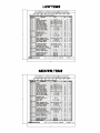
15.
DEFAULT SETTING VALUES
LAB
EL
DESCRIPTION
RANGE
DEFAULT
0.1 ÷ 25°C/1 ÷ 45°F
2.0°C / 4 °F
REGULATION
Hy
Differential
LS
Minimum Set Point
-55°C÷SET/-67°F÷SET
US
Maximum Set Point
SET÷99°C/ SET÷210°F
ot
First probe calibration
P2
oE
Second
probe
XR04CX)
Second
probe
XR04CX)
-9.9÷9.9°C/-18÷18°F
presence
(Only
calibration
(Only
-55 °C /55°F
99 °C /
99°F
0.0
n–Y
y
-9.9÷9.9°C/-18÷18°F
0.0
0
od
Outputs activation delay at start up
0 ÷ 99 min
AC
Anti-short cycle delay
0 ÷ 50 min
1
Cy
Compressor ON time faulty probe
0 ÷ 99 min
15
Cn
Compressor OFF time faulty probe
0 ÷ 99 min
30
CH
Kind of Action (Only XR03CX)
cL ÷ Ht
cL
DISPLAY
CF
Measurement units
°C - °F
°C / °F
rE
Resolution (only for °C)
dE – in
dE
Ld
Default Display (Only XR04CX)
P1-P2 - SP
P1
dy
Display delay
0 ÷ 15 min
0
DEFROST
td
Defrost type
EL – in
EL
8.0 °C / 46
°F
dE
Defrost termination temperature
-50÷50°C/-58÷122°F
id
Interval between defrost cycles
0 ÷ 99 hours
6
Md
Maximum length for defrost
0 ÷ 99 min.
30
1592020130 XR03_04CX GB 16.01.07.doc
XR03CX – XR04CX
dIXEL S.p.a.
Z.I. Via dell’Industria, 27 - 32010 Pieve d’Alpago (BL) ITALY
tel. +39 - 0437 - 98 33 - fax +39 - 0437 - 98 93 13
http://www.dixell.com E-mail: [email protected]
APPENDIX D:
USER SET POINTS
WARRANTY
HEREINAFTER REFERRED TO AS MANUFACTURER
FOURTEEN MONTH WARRANTY. MANUFACTURER’S PRODUCT IS WARRANTED TO BE FREE FROM DEFECTS
IN MATERIAL AND WORKMANSHIP UNDER NORMAL USE AND MAINTENANCE FOR A PERIOD OF FOURTEEN
MONTHS FROM THE DATE OF ORIGINAL SHIPMENT. A NEW OR REBUILT PART TO REPLACE ANY
DEFECTIVE PART WILL BE PROVIDED WITHOUT CHARGE, PROVIDED THE DEFECTIVE PART IS RETURNED TO
MANUFACTURER. THE REPLACEMENT PART ASSUMES THE UNUSED PORTION OF THE WARRANTY.
This warranty does not include labor or other costs incurred for repairing, removing, installing, shipping, servicing, or
handling of either defective parts or replacement parts.
The fourteen month warranty shall not apply:
1. To any unit or any part thereof which has been subject to accident, alteration, negligence, misuse or
abuse, operation on improper voltage, or which has not been operated in accordance with the
manufacturer’s recommendation, or if the serial number of the unit has been altered, defaced, or removed.
2. When the unit, or any part thereof, is damaged by fire, flood, or other act of God.
3. Outside the continental United States.
4. To labor cost for replacement of parts, or for freight, shipping expenses, sales tax or upgrading.
5. When the operation is impaired due to improper installation.
6. When installation and startup forms are not properly complete or returned within two weeks after startup.
THIS PLAN DOES NOT COVER CONSEQUENTIAL DAMAGES. Manufacturer shall not be liable under any circumstances for any consequential damages, including loss of profit, additional labor cost, loss of refrigerant or food products,
or injury to personnel or property caused by defective material or parts or for any delay in its performance hereunder
due to causes beyond its control. The foregoing shall constitute the sole and exclusive remedy of any purchases
and the sole and exclusive liability of Manufacturer in connection with this product.
The Warranties are Expressly in Lieu of All Other Warranties, Express of Implied and All Other Obligations or
Liabilities on Our Part. The Obligation to Repair or Replace Parts or Components Judged to be Defective in
Material or Workmanship States Our Entire Liability Whether Based on Tort, Contract or Warranty. We Neither
Assume Nor Authorize Any Other Person to Assume for Us Any Other Liability in Connection with Our Product.
MAIL CLAIM TO:
Hill PHOENIX
Hill PHOENIX
Display Merchandisers
1925 Ruffin Mill Road
Colonial Heights, VA 23834
1-800-283-1109
Refrigeration Systems &
Electrical Distribution Products
709 Sigman Road
Conyers, GA 30013
770-285-3200
07/09
Warning
Maintenance & Case Care
When cleaning cases the following must be performed
PRIOR to cleaning:
To avoid electrical shock, be sure all electric power is
turned off before cleaning. In some installations, more
than one switch may have to be turned off to completely de-energize the case.
Do not spray cleaning solution or water directly on fan
motors or any electrical connections.
All lighting receptacles must be dried off prior to insertion and re-energizing the lighting circuit.
Please refer to the Use and Maintenance section of this installation manual.
Tel: 1-800-283-1109
1925 Ruffin Mill Road, Colonial Heights, VA 23834
Due to our commitment to continuous improvement all specifications are subject to change without notice.
Hill PHOENIX is a Sustaining Member of the American Society of Quality.
Visit our web site at www.hillphoenix.com
BDM0714