1
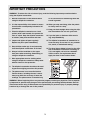
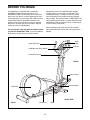
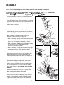
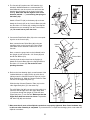
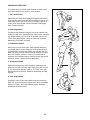
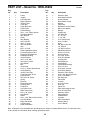
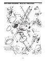
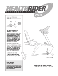
¨
Model No. HREL05982
Serial No.
USERÕS MANUAL
Serial Number Decal
QUESTIONS?
As a manufacturer, we are committed to providing complete
customer satisfaction. If you
have questions, or if there are
missing or damaged parts, we
will guarantee complete satisfaction through direct assistance
from our factory.
TO AVOID UNNECESSARY
DELAYS, PLEASE CALL DIRECT
TO OUR TOLL-FREE CUSTOMER
HOT LINE. The trained technicians on our customer hot line
will provide immediate assistance, free of charge to you.
CUSTOMER HOT LINE:
1-800-999-3756
Mon.ÐFri., 6 a.m.Ð6 p.m. MST
CAUTION
Read all precautions and instructions in this manual before using
this equipment. Keep this manual
for future reference.
Visit our website at
www.healthrider.com
new products, prizes,
fitness tips, and much more!
¨
TABLE OF CONTENTS
IMPORTANT PRECAUTIONS . . . . . . . . . . . . . . . . . . . . . . . . . . . . . . . . . . . . . . . . . . . . . . . . . . . . . . . . . . . . .3
BEFORE YOU BEGIN . . . . . . . . . . . . . . . . . . . . . . . . . . . . . . . . . . . . . . . . . . . . . . . . . . . . . . . . . . . . . . . . . . .4
ASSEMBLY . . . . . . . . . . . . . . . . . . . . . . . . . . . . . . . . . . . . . . . . . . . . . . . . . . . . . . . . . . . . . . . . . . . . . . . . . . .5
HOW TO USE THE ELLIPTICAL CROSSTRAINER . . . . . . . . . . . . . . . . . . . . . . . . . . . . . . . . . . . . . . . . . . . . .7
MAINTENANCE AND TROUBLESHOOTING . . . . . . . . . . . . . . . . . . . . . . . . . . . . . . . . . . . . . . . . . . . . . . . . .11
CONDITIONING GUIDELINES . . . . . . . . . . . . . . . . . . . . . . . . . . . . . . . . . . . . . . . . . . . . . . . . . . . . . . . . . . . .12
PART LIST . . . . . . . . . . . . . . . . . . . . . . . . . . . . . . . . . . . . . . . . . . . . . . . . . . . . . . . . . . . . . . . . . . . . . . . . . . .14
EXPLODED DRAWING . . . . . . . . . . . . . . . . . . . . . . . . . . . . . . . . . . . . . . . . . . . . . . . . . . . . . . . . . . . . . . . . .15
HOW TO ORDER REPLACEMENT PARTS . . . . . . . . . . . . . . . . . . . . . . . . . . . . . . . . . . . . . . . . . . .Back Cover
LIMITED WARRANTY . . . . . . . . . . . . . . . . . . . . . . . . . . . . . . . . . . . . . . . . . . . . . . . . . . . . . . . . . . .Back Cover
2
IMPORTANT PRECAUTIONS
WARNING: To reduce the risk of serious injury, read the following important precautions before
using the elliptical crosstrainer.
1. Read all instructions in this manual before
using the elliptical crosstrainer.
as an exercise aid in determining heart rate
trends in general.
2. It is the responsibility of the owner to ensure
that all users are adequately informed of all
precautions.
10. When you stop exercising, allow the pedals
to slowly come to a stop.
11. Keep your back straight when using the elliptical crosstrainer. Do not arch your back.
3. Place the elliptical crosstrainer on a level
surface, with a mat beneath it to protect the
floor or carpet. Keep the elliptical crosstrainer indoors, away from moisture and dust.
12. If you feel pain or dizziness while exercising, stop immediately.
4. Inspect and tighten all parts regularly.
Replace any worn parts immediately.
13. The elliptical crosstrainer is intended for inhome use only. Do not use it in any commercial, rental, or institutional setting.
5. Keep children under age 12 and pets away
from the elliptical crosstrainer at all times.
14. The decal shown below is found on the elliptical crosstrainer. If the decal is missing, or
if it is not legible, call toll-free 1-800-9993756 to order a free replacement decal.
Apply the decal in the location shown.
6. Always hold the handlebar or the upper
body arms when mounting, dismounting, or
using the elliptical crosstrainer.
7. Wear appropriate exercise clothing when
using the elliptical crosstrainer. Always wear
athletic shoes for foot protection.
8. The elliptical crosstrainer should not be used
by persons weighing more than 250 pounds.
9. The pulse sensor is not a medical device.
Various factors, including the userÕs movement, may affect the accuracy of heart rate
readings. The pulse sensor is intended only
WARNING: Before beginning this or any exercise program, consult your physician. This is especially important for persons over the age of 35 or persons with pre-existing health problems. Read all
instructions before using. ICON assumes no responsibility for personal injury or property damage
sustained by or through the use of this product.
3
BEFORE YOU BEGIN
Congratulations for selecting the revolutionary
HealthRider¨ E330 Elliptical Crosstrainer. The
HealthRider¨ E330 is an incredibly smooth exerciser
that moves your feet in a natural elliptical path, minimizing the impact on your knees and ankles. And the
unique E330 features adjustable resistance and
incline to help you get the most from your exercise.
Welcome to a whole new world of natural, ellipticalmotion exercise from HealthRider.
Department toll-free at 1-800-999-3756, Monday
through Friday, 6 a.m. until 6 p.m. Mountain Time
(excluding holidays). To help us assist you, please
note the product model number and serial number
before calling. The model number is HREL05982. The
serial number can be found on a decal attached to the
HealthRider¨ E330 (see the front cover of this manual
for the location of the decal).
Before reading further, please look at the drawing
below and familiarize yourself with the parts that are
labeled.
For your benefit, read this manual carefully before
you use the HealthRider¨ E330. If you have additional questions, please call our Customer Service
Book
Rack
Upper Body Arm
Console
Handlebar with Pulse Sensor
Resistance Control
FRONT
Incline Frame
Incline Bracket
Pedal Disk
RIGHT SIDE
BACK
Pedal Arm
4
Pedal
ASSEMBLY
Assembly requires two persons. Place all parts of the elliptical crosstrainer in a cleared area and remove the
packing materials. Do not dispose of the packing materials until assembly is completed.
The following tools are required for assembly: a phillips screwdriver
wrench
, a rubber mallet
, and pliers
1. Turn the Resistance Control (57) counterclockwise to
the minimum setting.
, an adjustable
.
1
If the Resistance Control (57) is attached to the Upright
(2), remove the Housing Screw (33). Pull the bottom of
the Resistance Control away from the Upright and then
slide it down to remove it.
Tab
57
33
2
2. Lay a cloth over the front of the Frame (1) to protect it.
Lay the Upright (2) in the position shown. Connect the
Extension Wire (51) to the Reed Switch Wire (50).
2
57
2
93
51
Next, connect the Resistance Cable (57) to the
Extension Cable (93) in the following way:
50
¥ Refer to drawing A. Pull up on the metal bracket, and
insert the tip of the Resistance Cable (57) into the
wire clip on the Extension Cable (93) as shown.
¥ Refer to drawing B. Firmly pull the Resistance Cable
(57) and slide it into the metal bracket on the
Extension Cable (93) as shown.
¥ Refer to drawing C. Using pliers, squeeze the prongs
on the upper end of the metal bracket together.
1
B
A
Metal
Bracket
C
57
57
3. Align the two holes in the front of the Upright (2) with
the two welded bolts in the front of the Frame (1).
Carefully push the Reed Switch Wire (not shown) into
the Upright until there is no slack.
57
93
93
3
Next, pivot the Upright (2) about halfway to the vertical
position while guiding the Split Plastic Sleeve (not
shown) into the Upright. Once the top edge of the Split
Plastic Sleeve is inside the Upright, pivot the Upright
to the vertical position so it rests on the four welded
bolts on the Frame (1). Be careful to avoid pinching
the wires.
26
Refer to assembly step 1. Insert the tab on the Resistance Control (57) into the Upright (2). Next, press the
bottom of the Resistance Control against the Upright.
Tighten the Housing Screw (33) into the Resistance
Control and the Upright.
5
2
26
5
Lift the front of the Incline Frame (5). Tighten a 3/8Ó
Nylon Locknut (26) onto each welded bolt.
93
1
4. The Console (87) requires two ÒAAÓ batteries (not
included). Alkaline batteries are recommended. To
install batteries, turn the console over and insert two
batteries into the battery clip as shown in the inset
drawing. Make sure that the negative ends of the
batteries (marked ÒÑÓ) are touching the springs in
the battery clip.
4
Batteries
87
90
Battery
Clip
Attach a Plastic Tie (90) to the battery clip as shown.
Attach the Console (87) to the Console Base (49) with
four Zinc #8 x 1/2Ó Screws (35), making sure that the
indicated wires are extending from the Console Base
(49). Be careful not to pinch the wires.
49
Wires
35
5. Connect the Reed Switch Wire (50) to the corresponding wire on the Console (87).
5
87
Next, connect the two Pulse Wires (86) to the two
remaining wires on the Console (87). Note: Either
Pulse Wire can be attached to either wire on the
Console.
Console
Wires
49
Next, connect the ground wire to the indicated hole in
the Upright (2) with a Zinc #8 x 1/2Ó Screw (35) and
the #8 Star Washer (53).
35
86
50
Carefully feed the wires down into the Upright (2).
Attach the Console Base (49) to the Upright with four
Zinc #8 x 1/2Ó Screws (35). Be careful to avoid
pinching the wires.
35
35
6. Refer to the inset drawing. Apply a small amount of the
included lubricant to a paper towel; rub a thin film of
lubricant onto the Chrome Extension Tube (21) on the
Right Pedal Arm (4). Slide the Chrome Extension Tube
into one of the Upper Body Arms (7).
Ground Wire
53
2
6
7
85
Slide the other Chrome Extension Tube (21) into the
other Upper Body Arm (7) in the same way.
21
Lube
Tap a 5/8Ó Axle Cap (85) onto one end of the Axle (19).
Insert the Axle through one of the Upper Body Arms
(7) and then through the Upright (2). Slide the other
Upper Body Arm (7) onto the Axle. Make sure that the
Upper Body Arms are turned as shown. Tap another
5/8Ó Axle Cap (85) onto the Axle.
19
4
7
85
7
2
7. Make sure that all parts of the elliptical crosstrainer are properly tightened. Note: Some hardware may
be left over after assembly is completed. To protect the floor or carpet from damage, place a mat under the
elliptical crosstrainer.
6
HOW TO USE THE ELLIPTICAL CROSSTRAINER
EXERCISING ON THE ELLIPTICAL CROSSTRAINER
INCLINE ADJUSTMENT
To mount the elliptical crosstrainer, hold the handlebar
and step onto the pedal that is in the lowest position.
Next, step onto the other pedal. Push the pedals until
they begin to move with a continuous motion. Note:
The pedal disks can turn in either direction. It is
recommended that you move the pedal disks in
the direction shown below; however, to give variety to your exercise, you may choose to turn the
pedal disks in the opposite direction.
The incline frame can be raised or lowered to vary the
intensity of your exercise. To raise the incline frame,
lift the end of the incline frame until the crossbar is on
top of the incline bracket. Make sure that the incline
frame is resting securely on top of the incline
bracket. To lower the incline frame, first lift the incline
frame slightly. Next, push the incline bracket toward
the upright and lower the incline frame onto the stabilizer.
To dismount the elliptical crosstrainer, wait until the
pedals come to a complete stop. CAUTION: The
elliptical crosstrainer does not have a freewheel;
the pedals will continue to move until the flywheel
stops. When the pedals are stationary, step off the
highest pedal first. Then, step off the lowest pedal.
Upright
Incline
Bracket
Crossbar
Pedal Disk
Pedal
Stabilizer
Incline
Frame
USING THE UPPER BODY ARMS
The upper body arms are designed to give you a total
body workout. As you exercise, hold the upper body
arms and move your arms forward and back in order
to work your arms, back, and shoulders.
If you want to exercise only your lower body, hold the
handlebar as you exercise.
HOW TO ADJUST THE RESISTANCE
To adjust the
intensity of
your exercise,
the resistance
of the pedals
can be adjusted. To increase
the resistance,
turn the resistance control
clockwise; to
decrease the
resistance, turn
the control
counterclockwise.
Upper
Body
Arms
Handlebar
Control
7
DESCRIPTION OF THE CONSOLE
HOW THE PACER PROGRAMS OPERATE
The innovative
console offers a
manual mode and
three pacer programs. The pacer
programs are
designed to help
you reach specific
exercise goals by
pacing your exercise. You can
choose from a stamina- building
Interval program,
an Aerobic program, and a special Fat Burn program. As you
exercise, seven
monitor modes will
provide continuous exercise feedback. The monitor
modes are described below:
When you use a
pacer program, two
Actual
columns of bars will
appear in the display. The left column represents a
target pace and the
Target
right column shows
your actual exercising pace. The target pace will change periodically during the program; as the target pace changes, simply
adjust your exercising pace to keep both columns at
the same height. Important: The target pace is a
goal pace. Your actual pace may be slower than
the target pace, especially during the first few
months of your exercise program. Be sure to exercise at a pace that is comfortable for you.
The three graphs
on the console
show how the
target pace will
change during the
programs. During
the Aerobic
program (P2), for example, the target pace will gradually increase during the first half of the program, and
gradually decrease during the last half of the program.
Each program will last for twenty minutes.
SpeedÑThis mode shows your exercising pace,
in kilometers or miles per hour (see HOW TO
SELECT KILOMETERS OR MILES on page 10).
TimeÑIf you select the manual mode, this mode
will show the elapsed time. If you select one of
the three pacer programs, this mode will count
down the time remaining in the program.
STEP-BY-STEP CONSOLE OPERATION
DistanceÑThis mode shows the distance you
have strided, in kilometers or miles.
Before the console can be operated, two batteries
must be installed. (See assembly step 4 on page 6.)
LapÑThis mode shows the number of laps you
have completed. One lap equals 0.25 kilometers
or miles.
Follow the steps below to operate the console.
1
CalorieÑThis mode shows the approximate
number of calories you have burned.
Turn on the power
To turn on the
power, press the
On/Reset
on/reset button
Button
or simply begin
exercising. The
entire display
will appear for
two seconds; the console will then be ready for
use. Note: If batteries were just installed, the
power will already be on.
ScanÑThis mode displays the above five
modes, for 5 seconds each, in a repeating cycle.
PulseÑThis mode shows your heart rate when
the pulse monitor is used. (See step 5 on page
9.)
8
2
The scan
modeÑ
Repeatedly
Mode
press the
Arrow
mode button
until an arrow
appears under
Mode
the scan symButton
bol. When the
scan mode is
selected, the
console will display the speed, time, distance, lap
and calorie modes, for 5 seconds each, in a
repeating cycle.
Select one of the three pacer programs or the
manual mode
To select one
of the pacer
Program Indicator
programs,
repeatedly
press the program button.
The program
indicator will
Program Button
show which
program you
have selected. To select
the manual mode, press the program button until
the program indicator disappears. The programs
will be selected in the following order: program 1
(Interval), program 2 (Aerobic), program 3 (Fat
Burn), manual mode.
3
The speed,
time, distance, lap,
or calorie
modeÑ
Repeatedly
press the
mode button
until an arrow appears below or above the
desired mode symbol. Make sure that there is not
an arrow under the scan symbol.
Begin your workout
If you selected the manuActual
al mode, go
to step 4. If
you selected
one of the
Target
pacer programs, two
columns of
bars will appear in the display. The left column
will show one bar, indicating a relatively slow
pace. The right column will show your actual
exercising pace. Adjust your exercising pace until
only one bar appears in the right column. Each
time the target pace changes during the program,
adjust your exercising pace to keep both columns
at the same height.
4
The pulse modeÑTo use the pulse mode, see
step 5.
To reset the display, press the on/reset button.
5
Measure your heart rate if desired
To use the
pulse sensor,
Metal
place your
Contacts
hands on the
metal contacts. Your
palms must be
resting on the
upper contacts
and your fingers must be
touching the lower contacts. Avoid moving your
hands. After a moment, the heart-shaped indicator in the display will begin to flash and your heart
rate will be shown. For the most accurate heart
rate reading, continue to hold the contacts for
about 15 seconds.
Follow your progress with the LED track and
the seven monitor modes
The LED
trackÑThe LED
track represents
a distance of
0.25 kilometers
or miles. As you
pedal, the indicators around
the track will light one at a time until you have completed one lap. A new lap will then begin.
Make sure that your hands are positioned as
described above, and that you are not moving
your hands excessively or squeezing the metal
contacts too tightly.
9
6
Turn off the power
To turn off the power, simply wait for about
six minutes. If the pedals are not moved and the
console buttons are not pressed for six minutes,
the power will turn off automatically.
HOW TO SELECT KILOMETERS OR MILES
The console can
display distance
and speed in
either kilometers
or miles. If a
ÒKPHÓ appears in
the display, distance and speed
will be shown in kilometers; if a ÒKPHÓ does not
appear, distance and speed will be shown in miles.
To change the
unit of measurement, first remove
the four indicated
screws from the
console. Lift the
console a few
inches and turn it
over; be careful
not to pull on the
wires.
Switch
Next, locate the
small switch on
Screws
the back of the
console. Slide the
switch up or down to change the unit of measurement.
Reattach the console with the four screws; be careful
not to pinch any of the wires.
10
MAINTENANCE AND TROUBLESHOOTING
Inspect and tighten all parts of the elliptical crosstrainer
regularly. Replace any worn parts immediately.
HOW TO LEVEL THE ELLIPTICAL CROSSTRAINER
For smooth
Incline
operation of
Frame
the elliptical
crosstrainer,
the incline
frame should
be kept clean.
Using a soft
cloth and mild
Wheel
detergent,
clean dust and
other residue
from the incline
frame where the wheels make contact with it. Other
parts of the elliptical crosstrainer can also be cleaned
in this manner. Never use abrasives or solvents.
If the elliptical
crosstrainer
does not sit
flat on the
floor, one or
Jam
both of the
Nut
Pad
leveling pads
should be
adjusted.
First, loosen
the jam nut on
each leveling
pad. Next,
turn the leveling pads as needed until the elliptical
crosstrainer is level. When the leveling pads are properly adjusted, firmly retighten the jam nuts.
LUBRICATING THE INCLINE BRACKET
PULSE SENSOR TROUBLE-SHOOTING
The incline
bracket and the
bolt on which it
pivots should be
regularly lubricated. Apply a small
amount of the
included lubricant
to the bolt and
between the
bracket and the
upright.
¥ Avoid moving your hands while using the pulse sensor. Excessive movement may interfere with heart
rate readings.
Upright
Bolt
Incline
Bracket
¥ Do not hold the metal contacts too tightly; doing so
may interfere with heart rate readings.
¥ For the most accurate heart rate reading, hold the
metal contacts for about 15 seconds.
¥ For optimal performance of the pulse sensor, keep
the metal contacts clean. The contacts can be
cleaned with a soft clothÑnever use alcohol,
abrasives, or chemicals.
11
CONDITIONING GUIDELINES
Burning Fat
The following guidelines will help you to plan your
exercise program. Remember that a proper diet and
adequate rest are essential for successful results.
To burn fat, you must exercise at a low intensity level
for a sustained period of time. During the first few
minutes of exercise, your body uses easily accessible
carbohydrate calories for energy. Only after the first few
minutes of exercise does your body begin to use stored
fat calories for energy. If your goal is to burn fat, adjust
the intensity of your exercise until your heart rate is
near the low end of your training zone as you exercise.
WARNING: Before beginning this or any exercise program, consult your physician. This is
especially important for persons over the age
of 35 or persons with pre-existing health
problems.
Aerobic Exercise
EXERCISE INTENSITY
If your goal is to strengthen your cardiovascular system, your exercise must be Òaerobic.Ó Aerobic exercise
is activity that requires large amounts of oxygen for
prolonged periods of time. This increases the demand
on the heart to pump blood to the muscles, and on the
lungs to oxygenate the blood. For aerobic exercise,
adjust the intensity of your exercise until your heart
rate is near the middle of your training zone.
Whether your goal is to burn fat or strengthen your
cardiovascular system, the key to achieving the
desired results is to exercise with the proper intensity.
The proper intensity level can be found by using your
heart rate as a guide. For effective exercise, your heart
rate should be maintained at a level between 70% and
85% of your maximum heart rate as you exercise. This
is known as your training zone.
WORKOUT GUIDELINES
You can find your training zone in the table below.
Training zones are listed according to age and physical condition.
AGE
UNCONDITIONED
TRAINING ZONE
(BEATS/MIN)
CONDITIONED
TRAINING ZONE
(BEATS/MIN)
20
138-167
133-162
25
136-166
132-160
30
135-164
130-158
35
134-162
129-156
40
132-161
127-155
45
131-159
125-153
50
129-156
124-150
55
127-155
122-149
60
126-153
121-147
65
125-151
119-145
70
123-150
118-144
75
122-147
117-142
80
120-146
115-140
85
118-144
114-139
Each workout should include three important parts:
(1) a warm-up, (2) training zone exercise, and (3) a
cool-down.
Warming up
Warming up prepares the body for exercise by
increasing circulation, delivering more oxygen to the
muscles, and raising the body temperature. Begin
each workout with 5 to 10 minutes of stretching and
light exercise to warm up.
Training Zone Exercise
After warming up, increase the intensity of your exercise until your heart rate is in your training zone for 20
to 30 minutes.
Cooling Down
Finish each workout with 5 to 10 minutes of stretching.
Stretching after exercise develops flexibility and helps
prevent post-exercise problems.
EXERCISE FREQUENCY
To maintain or improve your condition, plan three
workouts each week, with at least one day of rest
between workouts. After a few months of regular exercise, you may complete up to five workouts each
week, if desired.
12
SUGGESTED STRETCHES
The correct form for several basic stretches is shown at the
right. Move slowly as you stretchÑnever bounce.
1
1. Toe Touch Stretch
Stand with your knees bent slightly and slowly bend forward
from your hips. Allow your back and shoulders to relax as you
reach down toward your toes as far as possible. Hold for 15
counts, then relax. Repeat 3 times. Stretches: Hamstrings,
back of knees and back.
2
2. Hamstring Stretch
Sit with one leg extended. Bring the sole of the opposite foot
toward you and rest it against the inner thigh of your extended
leg. Reach toward your toes as far as possible. Hold for 15
counts, then relax. Repeat 3 times for each leg. Stretches:
Hamstrings, lower back and groin.
3. Calf/Achilles Stretch
With one leg in front of the other, reach forward and place
your hands against a wall. Keep your back leg straight and
your back foot flat on the floor. Bend your front leg, lean forward and move your hips toward the wall. Hold for 15 counts,
then relax. Repeat 3 times for each leg. To cause further
stretching of the achilles tendons, bend your back leg as well.
Stretches: Calves, achilles tendons and ankles.
3
4
4. Quadriceps Stretch
With one hand against a wall for balance, reach back and
grasp one foot with your other hand. Bring your heel as close
to your buttocks as possible. Hold for 15 counts, then relax.
Repeat 3 times for each leg. Stretches: Quadriceps and hip
muscles.
5
5. Inner Thigh Stretch
Sit with the soles of your feet together and your knees outward. Pull your feet toward your groin area as far as possible.
Hold for 15 counts, then relax. Repeat 3 times. Stretches:
Quadriceps and hip muscles.
13
PART LISTÑModel No. HREL05982
Key
No.
Qty.
1
2
3
4
5
6
7
8
9
10
11
12
13
14
15
16
17
18
19
20
21
22
23
24
25
26
27
28
29
30
31
32
33
34
35
36
37
38
39
40
41
42
43
44
45
46
47
48
49
50
1
1
1
1
1
2
2
1
2
1
1
1
1
2
1
1
6
2
1
2
2
4
6
1
1
5
2
1
1
3
6
4
1
1
9
1
1
2
1
2
1
1
6
6
2
2
1
1
1
1
Description
Key
No.
Qty.
51
52
53
54
55
56
57
58
59
60
61
62
63
64
65
66
67
68
69
70
71
72
73
74
75
76
77
78
79
80
81
82
83
84
85
86
87
88
89
90
91
92
93
94
95
#
#
#
#
1
1
1
1
1
2
1
2
2
1
2
2
4
2
1
1
3
1
1
1
1
8
14
3
2
4
2
4
2
3
10
2
2
2
2
2
1
1
1
6
1
1
1
1
1
1
2
1
1
Frame
Upright
Left Pedal Arm
Right Pedal Arm
Incline Frame
Crank Arm
Upper Body Arm
Large Pulley
Frame Bearing
3/4Ó x 1 1/4Ó Plastic Spacer
Flat Delrin Washer
Idler Bracket
Pulley
Idler Bearing
3/8Ó Push Nut
3/8Ó x 1Ó Screw
3/8Ó Flat Washer
Grip
5/8Ó x 10Ó Rod
Plastic Handlebar Sleeve
Chrome Extension Tube
Extension Tube Bushing
Handlebar Bushing
Incline Bracket
3/8Ó x 3 1/2Ó Bolt
3/8Ó Nylon Locknut
3/8Ó Washer
Belt
Incline Axle
5/16Ó x 1Ó Button Head Screw
Incline Bushing
Incline Frame Cap
Control Housing Screw
Eddy Bracket
Zinc #8 x 1/2Ó Screw
Spring
Flywheel
Flywheel Bearing
Flywheel Axle
Pedal Disk
Left Pedal Cover
Right Pedal Cover
#8 x 1 1/2Ó Screw
#10 Washer
Wheel
3/8Ó x 1 3/4Ó Button Head Screw
Left Side Shield
Right Side Shield
Console Base
Reed Switch/Wire
R1099A
Description
Extension Wire
Reed Switch Bracket
#8 Star Washer
Reed Switch Clamp
Magnet
Pulse Grip
Resistance Control/Cable
Black Lock Washer
Bumper
Upright Cap
3/4Ó Axle Cap
2Ó x 3Ó Cap
1Ó x 2Ó Cap
3 1/2Ó Round Cap
5/16Ó Jam Nut
Hook
3/8Ó Nylon Jam Nut
1/4Ó Eyebolt
1/4Ó Nylon Locknut
Adjustment Bracket
#8 x 2 1/2Ó Screw
#8 x 3/4Ó Screw
#10 x 3/4Ó Screw
5/16Ó Zinc Washer
Leveling Pad
Pedal Bushing
Pedal Wheel
Pedal Wheel Bearing
5/16Ó x 4Ó Bolt
5/16Ó Nylon Locknut
5/16Ó Black Washer
Extension Tube Spacer
5/16Ó x 3/4Ó Nylon Lock Bolt
5/16Ó Lock Washer
5/8Ó Axle Cap
Pulse Wire
Console
#8 x 1/2Ó Screw
5/16Ó Nut
Plastic Tie
Side Shield Support Strip
5/16Ó Shoulder Bolt
Extension Cable
Spring Bracket
Cable Bracket
Lubricant
Side Shield Decal
Warning Decal
UserÕs Manual
Note: # indicates a non-illustrated part. Specifications are subject to change without notice. See the back cover
of this manual for information about ordering replacement parts.
14
32
58
30
63
79
77
56
29
82
78
44
81
41
86
81
81
78
81
31
21
22
43
5
46
81
35
51
53
23
58 30
81
75
46
35
2
73
35
59
52
83
63
76
60
87
35
49
35
23
57
33
62
21
74
22
81
80
90
66
1
64
9
65
12
16
82
63
42
81
14
15
74
10
6
79
40
84
83
78
78 43
77 81
17
73
13
81
9
67 14
17
94
91
30 89 73
8
11
26 73
95
31
6
28
27
26
54
74
84
27
31
25
88
50
31
45
31
24
32 4559
62
76
80 40
73
44 3
61
72
64
44
73
43
67
73
47
48
4
76
17
76
55
63
39
7
85
71
38
93
61
68
72
67
17
7
38
92
69 70
37
18
23
72
20
73
73
72
80
34
36
85
19
15
R1099A
EXPLODED DRAWINGÑModel No. HREL05982
HOW TO ORDER REPLACEMENT PARTS
To order replacement parts, simply call our Customer Service Department toll-free at 1-800-999-3756, Monday
through Friday, 6 a.m. until 6 p.m. Mountain Time (excluding holidays). To help us assist you, please be
prepared to give the following information when calling:
¥ The MODEL NUMBER of the product (HREL05982).
¥ The NAME of the product (HealthRider¨ E330 Elliptical Crosstrainer).
¥ The SERIAL NUMBER of the product (see the front cover of this manual).
¥ The KEY NUMBER and DESCRIPTION of the part(s) from page 14 of this manual.
HealthRider¨ is a registered trademark of ICON Health & Fitness, Inc.
LIMITED WARRANTY
ICON Health & Fitness, Inc. (ICON), warrants this product to be free from defects in workmanship and
material, under normal use and service conditions, for a period of ninety (90) days from the date of purchase. This warranty extends only to the original purchaser. ICON's obligation under this warranty is limited to replacing or repairing, at ICON's option, the product through one of its authorized service centers.
All repairs for which warranty claims are made must be pre-authorized by ICON. This warranty does not
extend to any product or damage to a product caused by or attributable to freight damage, abuse, misuse,
improper or abnormal usage or repairs not provided by an ICON authorized service center, products used
for commercial or rental purposes, or products used as store display models. No other warranty beyond
that specifically set forth above is authorized by ICON.
ICON is not responsible or liable for indirect, special or consequential damages arising out of or in connection with the use or performance of the product or damages with respect to any economic loss, loss of
property, loss of revenues or profits, loss of enjoyment or use, costs of removal, installation or other consequential damages of whatsoever nature. Some states do not allow the exclusion or limitation of incidental or consequential damages. Accordingly, the above limitation may not apply to you.
The warranty extended hereunder is in lieu of any and all other warranties and any implied warranties of
merchantability or fitness for a particular purpose is limited in its scope and duration to the terms set forth
herein. Some states do not allow limitations on how long an implied warranty lasts. Accordingly, the above
limitation may not apply to you.
This warranty gives you specific legal rights. You may also have other rights which vary from state to state.
ICON HEALTH & FITNESS, INC., 1500 S. 1000 W., LOGAN, UT 84321-9813
Part No. 157826 R1099A
Printed in USA © 1999 ICON Health & Fitness, Inc.