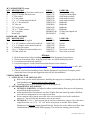
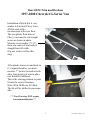
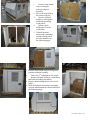
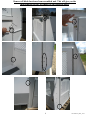
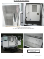
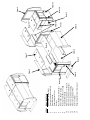
1
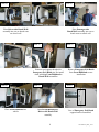
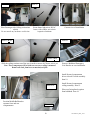
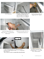
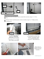
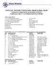
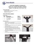
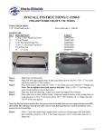
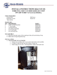
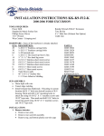
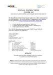
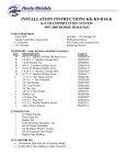
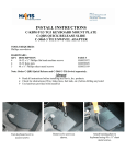
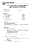
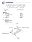
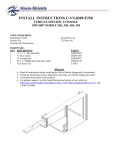
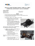
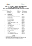
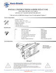
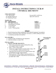
INSTALL INSTRUCTIONS KK-100-03 & KK-120-03
KWIK-KIT PRISONER TRANSPORT INSERT
FORD and CHEVY VAN PRISONER TRANSPORT
TOOLS REQUIRED:
¼” & 3/8” Ratcheting Wrenches
¼” & 3/8”Air Ratchets (recommended)
3/8” Impact Guns (recommended)
¼” & 3/8” Standard Socket Sets
Powered Drill
Powered Screwdriver (recommended)
Drill Bit Set
Tape Measure
Screwdriver Set
Awe or Scribe
Pry-bar
Wire Crimping tool
Wire Stripping tool
Wire Cutter
Circular Saw (for plywood)
Utility knife
Caulking gun
HARDWARE - 60” or 80” COMPARTMENT: Some hardware not used in all application:
PART #
USED FOR:
QTY DESCRIPTION
80
¼” Serrated nut
GSM30023
60
¼” x ¾” Carriage bolt
GSM32000
50
#10 x 1” Phillips pan head sheet metal screw
GSM33196
Floor/wall to ceiling
8
#8 x 3/8” Phillips flat head screw
GSM33179
Vent plates/dome lights
32
¼” x ¾” Phillips flat head machine screw
GSM33078
Wall/Bench extension
25
¼” x ¾” Hex head bolt
GSM33001
3rd divider, 3rd ceiling
25
¼” Flat washer
GSM31005
3rd divider, 3rd ceiling
15
½” Flat washer
GSM31009
Grab straps/seat belts
15
½” Lock washer
GSM31030
Grab straps/seat belts
15
½” x 1 ¼” Socket button head bolt
GSM33310
Grab straps/seat belts
4
3/8” x 2” Hex head bolt
GSM33032-1
Bulkheads
4
3/8” Hex nut
GSM30008
Bulkheads
4
3/8” Lock washer
GSM31028
Bulkheads
4
3/8” x 2” Fender washer
GSM31022
Bulkheads
2
White Silicone tube
PRM97343
Seams & Gaps
4
Lock key
PRM97660-1
Doors
4
Vent block off plate
KKM0403-004 Ceiling (vent adapter kit)
2
A/C vent plate
KKM0403-001 Ceiling (vent adapter kit)
2
Dome light
KK-DOME-2
Ceiling
HARDWARE - 40” COMPARTMENT:
QTY DESCRIPTION
90
¼” x ¾” Carriage bolt
90
¼” Serrated nut
PART #
GSM32000
GSM30023
USED FOR:
40” COMPARTMENT (cont):
QTY DESCRIPTION
40
#10 x 1” Phillips pan head sheet metal screw
25
#8 x 3/8” Phillips flat head screw
5
½” Flat washer
5
½” Lock washer
5
½” x 1 ¼” Socket button head bolt
5
3/8” x 2” Hex head bolt
5
3/8” Hex nut
5
3/8” Lock washer
5
3/8” x 2” Fender washer
2
A/C Vent plate
1
Dome light
PART #
GSM33196
GSM33179
GSM31009
GSM31030
GSM33310
GSM33032-1
GSM30008
GSM31028
GSM31022
KKM0403-001
KK-DOME-2
USED FOR:
Floor, wall to ceiling
Vent plates/dome lights
Grab straps/seat belts
Grab straps/seat belts
Grab straps/seat belts
Bulkheads
Bulkheads
Bulkheads
Bulkheads
Ceiling (vent adapter kit)
Ceiling
HARDWARE – DIVIDER:
QTY DESCRIPTION
28
¼” x 1 ½” Hex head lag bolt
14
¼” x 5/8” Stainless socket button head bolt
7
¼” x ¾” Stainless socket button head bolt
14
¼” Stainless flat washer
10
#10 x ½” Phillips flat head machine screw
10
#10 Thin nylock nut
PART #
GSM33062
GSM33308
GSM33309
GSM31048
GSM33072
GSM330015-1
USED FOR:
Divider to floor
Divider
Divider
Divider
Door frame to divider
Door frame to divider
Always!
Read all instructions before installing any Havis-Shields Equipment Corp products.
Check for obstructions (Wire, brake lines, fuel tank, etc.) before drilling any holes!
Use hardware provided with install kit
For product support, visit the Install Instructions Section of our website at
http://havis.com/Installation/Installation.html, email [email protected] or call 1-800524-9900.
If this is your first time installing a Havis Shields Equipment Corp Prisoner Transport, please
contact the factory for tips and suggestions that will ease the installation.
VEHICLE PREPERATION:
1. STEPS, HVAC, VAK, OPTIONS, ETC:
• Refer to the specific install instructions. Installing the steps prior to installing the Kwik Kit will
ease installation and must be done on Chevy side step.
•
Installing options may be necessary prior to installing the kit.
2. SOUND DEADENING & FLOORING:
• OPTION #1: KK-RFM A self-adhesive rubber sound deadening floor mat is sold separately
and will help deaden road noise.
• Install optional rubber flooring onto van floor. Rubber floor mat should go under OEM floor
mat in drivers compartment to cover sheet metal floor.
• Excess material can be placed onto walls of the van, around the wheel wells, inside door
panels, etc. This will also help deaden the echo in the vehicle.
• OPTION #2: 3/8” to ½” plywood can also be used as an alternative solution. Cover the entire
cargo floor of the van. (1 ½) – 48” x 96” sheets of plywood are needed. Havis Shields
Equipment Corp does not supply plywood floor kit. Draw a line on the rubber/wood floor from
rear doorframe as shown on the following page. This will be the starting point of the kit.
2
KK-XXX-03_INST_10-07
Rear OEM Trim modifications
1997-2008 Chevrolet G-Series Van
Installation of Kwik Kit is very
similar in Ford and Chevy Vans.
All kits start with a
measurement at the rear floor.
The rear plastic floor trim on
Chevy vans must be cut straight
across as shown in photo.
Measure seven inches (7 1/4”)
from rear center of trim and cut
straight-line full width.
(Jig saw works well for this
step)
After plastic trim is cut and back in
it’s original location, you must
measure 7” inches forward on both
sides from newly cut trim to place
rear Kwik Kit bulkhead.
This is the starting position so parts
fit into the correct locations.
Note: With OEM rear AC/Heat,
The kit will be shifted to passenger
side.
. *** Ford Van does NOT require
rear trim modification***
3
KK-XXX-03_INST_10-07
Ford Driver-Side rear
Ford Passenger-Side rear
8” inches
8”inches
3. PASSENGER WINDOW VAN PREPARATIONS:
***Kwik kits are designed for cargo vans with no rear OEM trim, however they can be installed
into passenger window vans. Some rear trim removal or modification is required. Do not remove
all rear trim and headliner as this will aid in sound deadening & insulation
Note: Kwik Kits are recommended for Cargo Vans. The installer must determine modifications
to the interior of a window van.
1. Remove all rear bench seats from the vehicle.
2. Modify / remove interior parts as needed.
3. Remove floor mat/carpet and replace with ½” plywood or sound deadening material.
(Recommended).
4. If installing KK-F-VAK, (OEM air conditioning adapter) cut or remove all plastic trim around
the rear OEM system.
UNPACKING AND INSTALLATION:
***Refer to exploded view drawing on page 22 to identify parts ***
4
KK-XXX-03_INST_10-07
1.
2.
3.
4.
5.
Remove clear shrinkwrap covering the
prisoner transport
assembly.
This is the rear 40/60/or
80 section of the kit.
Remove all black
hardware, wood panels
and brackets holding
wood panels.
Remove bolts
holding the kit to the
wood pallet.
With all hardware
removed the remaining
sections should match
the sub-assemblies on
the following pages
1. Remove clear shrink-wrap covering from
prisoner transport assembly.
2.
This is the 3rd compartment, 40 section
3.
Remove all black hardware, wood fillers,
and brackets holding assemblies.
4. Remove bolts holding the kit to the wood
pallet.
5. With all hardware removed the remaining
sections should match the sub-assemblies on
the following pages
5
KK-XXX-03_INST_10-07
Remove all black hardware from assembled unit. This will give you the
subassemblies as they are shown on the following pages.
6
KK-XXX-03_INST_10-07
VERY IMPORTANT:
Be sure that all Auxiliary lighting, video systems, Kwik kit options, and
wiring are complete. Access is severely limited after kit is installed.
Notch trim
for wiring
“B” Pillar
1 ½” Hole
If optional rear load light(s)
(KK-RLL) was ordered, install at
this time.
See KK-RLL install instructions
Run all wiring for dome lights, power
vents, video system, HVAC, etc. at
this time. Tie to existing OEM harness
For neatness of wiring, route all
cables down driver-side “B” pillar.
If going under hood for power to
console, drill hole at location above.
Be sure to tape harnesses to roof in
approximate locations that
accessories are being installed in
Kwik kit. This will vary between
the different model kits.
At this time go to the KK- (x)-VAK
install instructions. This must be
installed prior to Kwik Kit.
If optional Power Vent(s)
(KK-PVENT) was ordered, see
those instructions at this time for
necessary prep work that must be
done prior to installing Kwik Kit
7
KK-XXX-03_INST_10-07
Item #1
Item #2
Place Driver-side Bench/Wall
assembly into van so bench rests
on wheel well
Place Passenger-side
Bench/Wall assembly into van so
bench rests on wheel well
Item #3
Item #3
Remove steel support bracket for
Emergency Exit Hatch pin. Re-install
when attaching Front Bulkhead to
Bench/Wall assemblies
Item #3
Place Front Bulkhead into
vehicle
Item #3
Remove Emergency Exit Hatch
from Front Bulkhead to ease
installation
Item #3
Attach Front Bulkhead to
Driver-side Bench/Wall
assembly
8
View of Emergency Exit Hatch
support bracket assembled.
KK-XXX-03_INST_10-07
Item #4 & #13
Be careful that exposed wires are not touching metal and optional KKx-VAK hoses are not completely crushed
Note: Vent hose will be tight in spots. If hose are crushed to an oval
shape the airflow will still be good. Avoid completely crushing hoses.
Place (2) Diamond Plate Floors
between Bench/Wall assemblies and
Front bulkhead. Place cardboard
along side of bench while positioning
the floor to avoid scratching the bench.
Item #5
Item #5
Item #3
Item #4
The floor(s) will square the benches
and bulkheads to the kit.
Place Center Divider into vehicle.
Item #5 to #3
Loosely bolt Center Divider to
Front Bulkhead
NOTE: Some installers
prefer to install ceiling
prior to divider.
Item #7
Current view of installation
9
Carefully place Driver-side
Ceiling section into vehicle.
KK-XXX-03_INST_10-07
Item #8
Place Passenger-side Ceiling section into
vehicle
Do not attach any hardware at this time
Item #8
Route dome light wires, HVAC
hoses, video cables, etc to their
respective locations
Item #7 & #8
Current view of installation
Item #9
Item #7 & #8
Slide the ceiling sections out of the way in order to access A/C hoses, wires, etc.
Note: These components will be hard to access once ceiling is mounted.
Remove all slack from hoses to maximize airflow.
Item #12
Item #9
Item # 10
Remove Bulkhead Emergency
Exit Hatches to ease installation.
Install forward compartment
driver sidewall / bench assembly.
Item 10.
Install forward compartment
ceiling assembly. Item 12.
Place rear facing bench against
front bulkhead. Item 16.
Position Middle Bulkhead to
separate front and rear
compartments
Item # 16
10
KK-XXX-03_INST_10-07
Rear Facing bench
Attach floor flange and side seat
flange with # 10 x ¾” pan head sheet
metal screws.
Use under seat flange holes to mark
and Drill through front bulkhead
with ¼” bit. Use ¼” x ¾” bolts and
serrated to attach seat to bulkhead.
Drill floor flange and side seat
flange with a 5/32” drill bit.
Attach seat cover plate with # 10 x
½” flat head sheet metal screws.
Item #9 to #2
Loosely bolt Passenger-side rear ceilings, Bench/Wall
assembly to Middle Bulkhead using ¼” x ¾” Carriage bolts
and serrated nuts
Note: An awe or scribe is recommended to help align holes.
11
Bolt side door and door-frame
assembly using ¼” x ¾” carriage
bolts, washers and nuts.
KK-XXX-03_INST_10-07
Item #6
to #5
Item #6
Item #6
Place Rear Bulkhead
Doorframe into vehicle
Position between Driver and
Passenger-side Bench/Wall
assemblies
Loosely attach Doorframe to Center
divider using #10 x 3/8” flat head
machine screws and nylock nuts
Item #6 to #2
Item #11
Loosely bolt Rear Bulkhead
Doorframe (at the door hinge) to
Bench/Wall assemblies using ¼”
x ¾” carriage bolts, washers and
serrated nuts
Note: It is recommended to put
edge molding on the OEM door
opening on the passenger side to
avoid damaging the Kwik kit
door.
Item #11
to #9
Place the 3rd Compartment
Doorframe assembly.
Item #12 to #11
Align 3rd Compartment Doorframe to
3rd Compartment Ceiling and loosely
attach ¼” x ¾” hex head bolts, washers
and serrated nuts.
Press doorframe to align with holes in
Passenger-side Bench/Wall
assembly.
12
KK-XXX-03_INST_10-07
Item #6
to #5
Item #7, #8, #12 to #3, & #6
Continue around the entire kit bolting
all Ceiling pieces to Bulkheads and
Doorframes using ¼ x ¾” carriage
bolts, washers, and serrated nuts
An awe or scribe will help
align the holes
Tighten screws holding Rear
Doorframe to Center Divider
Pry bar
Cut door gasket with utility knife. Cut gasket to the length
of door acceptor frame. Attach as shown above.
Position the entire unit according to the
measurements on the following page.
Note: Maneuver the kit into position.
THE FOLLOWING STEPS ARE EXTREMLY CRITICAL FOR A SUCCESFULL
INSTALLATION! PLEASE FOLLOW THESE INSTRUCTIONS CAREFULLY.
Lower Driver-Side rear
Lower Passenger-Side rear
Item #1
Rear driver-side
doorframe wing
¼”
8”inches
Position of driver-side Rear
Doorframe when installing with
factory rear air There should be at
least ¼” of space between the
A/C blower motor and wing
Measurement from driver-side
Rear Doorframe to vehicle
doorframe shown above
13
8” inches
Measurement from passenger-side
Rear Doorframe to vehicle
doorframe shown above
KK-XXX-03_INST_10-07
Top Driver-Side rear
Top Passenger-Side rear
Item #6
Approximately 3”inches
Item #6
3” inches
Item #7 to #1
Item #6
With unit positioned according to measurements on previous page, predrill and attach a #10 x 1” sheet metal screw to hold the rear Bulkhead in
place while assembling the remainder of the unit.
14
Position Driver-side Ceiling section to
mate with Bench/Wall assembly. Predrill 5/32” holes into Ceiling, using
Bench/Wall assembly holes as a guide.
KK-XXX-03_INST_10-07
Be careful when predrilling not to hit
hoses, wires, etc…
Note: Ceiling is behind wall
Item #8 to #2
Item #5 & #4 to van floor
Pre-drill ceiling with 5/32” drill bit and attach #10 x
1” Phillips pan head sheet metal screws to hold
Ceiling to Bench/Wall assembly. Repeat these steps
on the Passenger-side Ceiling section
Item #5 through #8 into #7
Pre-drill through Ceiling sections, (using
Divider as a template), with 3/16” drill
bit and attach using ¼” x 1 ½” hex head
lag bolts
Be Sure Floor Is Square To Benches & Bulkheads.
Attach Divider to vehicle. Pre-drill through floor(s)
using 3/16” drill bit and attach using ¼” x 1 ½” hex
head lag bolts
Item #4 through #1 into van floor
Item 4 through #1 into van floor
Attach remainder of Diamond plate floor. Pre-drill
diamond floor (only) w/ 3/16” hole and 1/8” hole through
floor of vehicle
Through Item #4, #1, & van floor
Attach to wood floor or rubber
floor mat using #10 x 1” Phillips
pan head sheet metal screws
Begin to tighten ALL loose hardware on the remainder of the unit,
being sure to align edges and bends of materials being tightened. This
will square the unit to itself.
15
KK-XXX-03_INST_10-07
On the Rear doorframe, remove the
sheet metal screws installed earlier. Drill
3/8” holes through the doorframe, floor,
and vehicle. Attach using 3/8” x 2” hex
head bolts, washers, fender washers, lock
washers, and hex nuts.
Item #6 to van floor
Item #11 to van floor
3/8” x 2” Hex head
bolt, washers, and nut
Item #11 to van floor
On 3rd Compartment Doorframe repeat the same steps done on Rear Doorframe. Only one bolt
is used and must be located just to the left of the doors hinge as shown above.
3/8” x 2” hex head bolt, flat washer,
fender washer, lock washer, and nut
Item #3 to van floor
Item #11
Secure the Front Bulkhead. Drill (2- one
per-side) 3/8” holes through the frame, ½”
plywood, and floor of vehicle Attach using
3/8” x 2” hex head bolt, flat washer, fender
washer, and nut.
Attach the doorframe to the vehicle
using #10 x 1” Phillips pan head sheet
metal screws
16
KK-XXX-03_INST_10-07
Socket
Pin
Item #14 to doors and frames
Attach Ball & Socket Style Doorstop.
1st Attach “Pin” portion of assembly. Attach to threaded hole on the door using a ¼” x 1” Hex
head bolt.
2nd Attach the “Socket” and bracket portion. Attach to doorframe using #8 x ¾” Phillips machine
screws and keps nuts.
Item #11
Item #15
In the upper corner of each side
of the 3rd Compartment
Doorframe are small filler
panels that need to be installed.
Attach using ¼” x ¾” carriage
bolts, washers, and serrated
nuts.
Place trim panels as shown above
Pre-drill through trim panel (only)
with 3/16”. Pre-drill the vehicle
w/ 1/8” hole and attach panels
using #10 x 1” sheet metal screws
Silicone all seems
and joints. This will
allow the unit to be
hosed out.
17
KK-XXX-03_INST_10-07
FINAL INSTALLATION PHOTOS
Forward Compartment for models
KK-100-03, KK-100-04, KK-120-03 and KK-120-04
Optional Storage Compartment
(Sold Separately)
18
KK-XXX-03_INST_10-07
PRISONER TRANSPORT OPTIONS – (All SOLD SEPERATLEY)
KR-CCL-1
KR-DL
KK-PVENT
KK-RLL
C-VS-1800-ECO w/
C-TCB-7 & C-3090-7
PT-VIDEO-X
19
KK-XXX-03_INST_10-07
ITEM
1
2
3
4
5
6
7
8
9
10
11
12
13
14
15
DESCRIPTION
Driver-side Bench/Wall
Passenger-side Bench/Wall
Front Bulkhead
Diamond-plate Floor
Divider
Rear Bulkhead/ Doorframe Item 14
Driver-side Rear Ceiling
Passenger-side Rear Ceiling
Separator Bulkhead
Front Compartment “L” Bench
Front Compartment Doorframe
Front Compartment Ceiling
Front Compartment Floor
(2) Door Stops
Item 6
Diamond-plate floor filler panel
Item 1
Item 15
Item 4
Item 7
Item 8
Item 2
Item 9
Item 10
Item 12
Item 13
Item 14
Item 11
Item 3