1
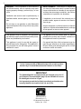
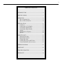
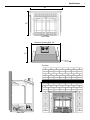
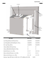
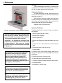
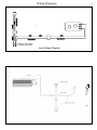
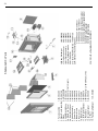
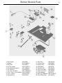
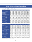
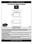
ShadowLight XL
Direct Vent Gas Fireplace Insert
Owners Manual
R2
8/06
WARNING: If the information in this manual is not followed
exactly, a fire or explosion may result causing property
damage, personal injury or loss of life.
Installation and service must be performed by a qualified
installer, service agency, or the gas supplier.
Do not store or use gasoline or other flammable vapors
and liquids in the vicinity of this or any other appliance.
FOR YOUR SAFETY:
WHAT TO DO IF YOU SMELL GAS
• Do not touch electrical switches.
• Do not try to light any appliance.
• Open windows.
• Extinguish any open flame.
• Do not use the phone in your building.
• Immediately call your gas supplier from a neighbor's
phone.
• Follow the gas supplier's instructions.
• If you cannot reach your gas supplier, call the fire
department.
ADVETISSEMENT: Quinconque ne respect pas à la
lettre les instructions dans le présent manuel risque de
déclencher un incendie ou une explosion entraíant des
dommages matérials, des lésions corporelles ou la perte
de vies humaines.
L’installation et service doit être exécuté par un qualifié
installer, agence de service ou le fourmisseur de gaz.
Ne pas entreposer ni utiliser d'essence ni d'autres vapeurs
ou liquides inflammables dans le voisinage de cet appareil
ou de tout autre appareil.
POUR VOTRE SÉCURITÉ: Que faire si vous sentez une
odeur de gaz:
• Ne pas tenter d'allumer d'appareil.
• Ne touchez à aucun interrupteur. Ne pas vous servir
des téléphones se trouvant dans le batiment où vous
trouvez.
• Evacuez la pièce, le bâtiment ou la zone.
• Appelez immédiatement votre fournisseur de gaz depuis
un voisin. Suivez les instructions du fournisseur.
• Si vous ne pouvez rejoindre le fournisseur de gaz, appelez le service dos incendies.
Tested by Intertek Testing Services/Warnock Hersey; 8431 Murphy Drive, Middleton, WI 53562
Part #3-90-00395
2
WARNING: If the information in this manual is
not followed exactly, a fire or explosion may result
causing property damage, personal injury or loss
of life.
Installation and service must be performed by a
qualified installer, service agency, or the gas supplier.
Do not store or use gasoline or other flammable
vapors and liquids in the vicinity of this or any other
appliance.
ADVETISSEMENT: Quinconque ne respect pas
à la lettre les instructions dans le présent manuel
risque de déclencher un incendie ou une explosion
entraíant des dommages matérials, des lésions
corporelles ou la perte de vies humaines.
L’installation et service doit être exécuté par un
qualifié installer, agence de service ou le fourmisseur de gaz.
Ne pas entreposer ni utiliser d'essence ni d'autres
vapeurs ou liquides inflammables dans le voisinage
de cet appareil ou de tout autre appareil.
This appliance may be installed in an aftermarket
permanently located, manufactured (mobile) home,
where not prohibited by local codes.
Cet appareil peut être installé dans un maison
préfabriquée (mobile) déjà installée à demeure si
les règlements locaux le permettent.
This appliance is only for use with the type(s) of
gas indicated on the rating plate. This appliance is
not convertible for use with other gases, unless a
certified kit is used.
Cet appareil doit être utilisé uniquement avec les
types de gas indiqués sur la plaque signalétique.
Ne pas l’utiliser avec d’autres gas sauf si un kitde
conversion cerifié est installé.
“In the Commonwealth of Massachusetts, this product must be
installed by a licensed Massachusetts Plumber or Gas Fitter”
IMPORTANT
The Shadowlight XL is manufactured and shipped set up for LP
gas (Propane). Conversion kits (page 14) are available to convert
to natural gas or back to LP gas.
It is important to mark the fuel label accordingly so that the value
is easily identified as to which fuel it is set up for.
Manufactured by:
Harman Stove Co.
352 Mountain House Road
Halifax, PA 17032
3
TABLE OF CONTENTS
INTRODUCTION ........................................................... 4
SPECIFICATIONS ......................................................... 5
OPERATION ................................................................... 8
How to Light the Fire ................................................ 9
How to Turn Off the Fire ......................................... 10
INSTALLATION ........................................................... 11
Clearances ............................................................... 12
Connecting to a Gas Supply .................................... 13
Converting to Natural Gas ....................................... 15
Converting to High Altitude .................................... 17
Venting..................................................................... 18
Installing into a Fireplace ........................................ 20
Options .................................................................... 24
MAINTENANCE .......................................................... 25
Removing the Glass................................................. 25
Replacing the Gasket ............................................... 25
Cleaning the Glass ................................................... 25
Cleaning the Log Set and Firebox ........................... 25
Convection Blower Service Access.................. ....... 26
WIRING DIAGRAM..................................................... 27
PARTS LIST ....................................... ......................... 28
TROUBLE SHOOTING................................................ 30
WARRANTY ................................................................. 34
4
Introduction
The installation of the ShadowLight XL Fireplace Insert
must conform with local codes, or in the absence of local
codes, with National Fuel Gas Code, ANSI Z233.1 (NFPA
54). Installer l'appareil selon les codes ou règlements
locaux, ou, en l'absence de tels règlements, selon les
Codes d'installation CAN/CGA-B149.
The ShadowLight XL Fireplace Insert may be installed
in mobile homes.
CAUTION: This appliance must be vented to the
outside.
Installation and repair of the ShadowLight XL Fireplace
Insert should be done by a qualified service person.
The appliance should be inspected before use and
at least annually by a qualified service person. More
frequent cleaning may be required due to excessive lint
from carpeting, bedding material, etc. It is imperative
that control compartments, burners, and circulating air
passageways of the appliance be kept clean. Any safety
screen or guard removed for servicing an appliance must
be replaced prior to operating the appliance.
S'ASSURER QUE LE BRÛLEUR ET LE COMPARTIMENT
DES COMMANDES SONT PROPRES. VOIR LES
INSTRUCTIONS D'INSTALLATION ET D'UTILISATION
QUI ACCOMPAGNENT L'APPAREIL.
When operating your Harman ShadowLight XL Fireplace
Insert, respect basic safety standards.
Read these instructions carefully before you attempt
to operate the heater. Failure to do so may result in
damage to property or personal injury and may void the
product warranty.
Consult with your local building code agency and insurance
representative before you begin your installation to
ensure compliance with local codes, including the need
for permits and follow-up inspections.
Observing required clearances to combustible materials,
proper connection to an approved venting system, and
the accessibility of the gas and electrical supply must
all be considered when planning the installation of a
ShadowLight XL Fireplace Insert.
Install the ShadowLight XL Fireplace Insert only in
a listed solid-fuel burning factory-built fireplace or
a masonry solid-fuel burning fireplace. The Fireplace
Insert and vent should be enclosed when installed in,
or when passing through, a living area where children
may come in contact with it.Z21.88-2002-CSA 2.332002,CAN/CGA2.17.
Listed Direct Vent Gas Fireplace Heater
Radiateur Ventile
Model: ShadowLight XL Gas Fireplace Insert
• Homologue Pour Le Canada
• Do not remove this label.
• Not for use with solid fuel. Not for use with air filters. Ne doit pas etre
utilise avec un combustible solide.
• Also for use in mobile (manufactured) homes after home is sited.
• Tested to ANSI Z21.88-2002 / CSA2.33-2002 / CAN-CGA-2.17-M91
• For use with natural gas or propane. A conversion kit, as supplied by the
manufacturer, shall be used to convert this room heater to the alternate
fuel. Pour utilisation, avec le gaz naturel et le propane. Une trousse de
conversion fournie par le fabricant doit etre utilisee pour passer d’un
combustible a l’autre.
• Keep burner and control compartment clean. See installation and
operating instructions accompanying appliance. S’assurer que le bruleur
et le compartiment des commandes sont propres. Voir les instructions
d’installation et d’utilisation qui accompagnent l’appareil.
• During repairs or maintenance of this unit, all sealing gaskets or high
temperature silicone seals on the heat exchanger module must be inspected for damage and replaced, if necessary, to prevent any leakage
of exhaust into the living areas.
• Electrical Rating: 115 VAC, 60 Hz, < 1.15 AMP
RATINGS
NATURAL PROPANE
Input Rating(Btu/hr)(0-2000 ft)(0-610m)
35,000
35,000
Input Rating(Btu/hr)(2000-4500ft)(610-1375m) 34,000
34,500
Min. Input Rating(Btu/hr)
21,600
20,900
Orifices (DMS)(0-2000 ft)(0-610m)
31
50
Orifices (DMS)(2000-4500ft)(610-1375m)
33
51
Manifold Pressure (in w.c./kPa)
3.5/.87
2.5
Min. Manifold Pressure (in w.c./kPa)
1.3/.32
3.6/.9
Min. Inlet Pressure (in w.c./kPa)
5.0/1.24 11.0/2.75
WHI #
MANTEL CLEARANCE: Combustible mantle up to 8” in depth must be
at least 43” above unit base.
CAUTION: Do not operate the appliance with glass removed, cracked
or broken. Replacement of panel(s) should be done by a licensed or
qualified service person.
CAUTIONNER: N’orére l’appareil avec le verre enlevé, craque ou casse.
Le remplacement du panneau(s) devrait être fait par une personne de
service qualifie ou autorise.
CAUTION: Hot while in operation. Do not touch. Severe burns may
result. Keep children, clothing, furniture, gasoline and other liquids
having flammable vapors away.
ATTENTION: Les surfaces sont chaudes en service. Ne touchez pas.
Risque de brulure grave. Tenez les enfants, les vatements, le mobilier,
l’essence et autres liquides produisant des vapeurs inflammables B
distance.
This appliance is only for use with the type of gas indicated on the rating plate and may be installed in an aftermarket, permanently located,
manufactured (mobile) home where not prohibited by local codes. See
owner’s manual for details. This appliance is not convertible for use
with other gases, unless a certified kit is used.
A LABEL (LOCATED NEAR THE BURNER SYSTEM MODULE) STATES THE FUEL FOR WHICH THE HEATER IS
EQUIPPED.
Manufactured by Harman Stove Company
352 Mountain House Road, Halifax, PA 17032
20 Airport Road, West Lebanon, NH 03784
SAFETY LABEL
Specifications
40”
30”
Front View
Minimum Opening Size: 29”
Inlet
Outlet
14”
Top View
13”
Side View
Front View
5
6
Specifications
On-Off- Thermostat
Switch
Glass Door
Face Bolt
Burner
Pilot
Burner Plate
Leveling Bolt
Hi-Low Knob
Lighting
Instructions
Igniter
Blower Speed
Switch
Leveling Bolt
Latch Handle
On-Off-Pilot
Knob
Safety Label
Face Bolt
Specifications
7
Air Intake
Vent
On-Off
Thermostat
Switch
On-Off
Thermostat
Switch
Connector
Leveling Bolt
RATINGS
NATURAL
PROPANE
Input Rating (Btu/hr)(0-2,000 ft)(0-610m)
35,000 BTU
35,000 BTU
Input Rating(Btu/hr)(2000-4500ft)(610-1375m)
34,000 BTU
34,500 BTU
Min. Input Rating (Btu/hr)
21,600 BTU
20,900 BTU
Orifices (DMS)(0-2000 ft)(0-610m)
31
50
Orifices (DMS)(2000-4500ft)(610-1375m)
33
51
Manifold Pressure (in w.c./kPa)
3.5 / .87
10.0 / 2.49
Minimum Manifold Pressure (in w.c./kPa)
1.3 / .32
3.6 / 0.9
Minimum Inlet Pressure (in w.c./kPa)
5.0 / 1.25
11.0 / 2.74
Maximum Output (BTU/hr)(0 to 4,500 ft.)(0 to 1,375 m)(Blower off) 27,600
28,600
8
Operation
Warning
Doors Are Hot While In Operation. Wear Gloves
and Only Touch Doors On The Handles.
PILOT
Pilot Location Shown Above
Door Handles
ON-OFF/
THERMOSTAT
Switch
Lift bottom grill with index
finger and fold down to
access controls
ON
OFF
THERMOSTAT
Blower Speed
Switch
Piezo Igniter
Button
● Pull
lighting instruction
plate out to view text.
● Push back in before
closing grills.
UP - ON
MIDDLE - OFF
DOWN - THERMOSTAT
9
Operation
Operation
HOW TO LIGHT THE FIRE
1. STOP! Read the safety information on the front
cover.
High-Low
2. If using the optional thermostat, set thermostat to
the lowest setting.
3. Turn off electric power to the appliance.
4. Turn the ON-OFF/THERMOSTAT switch to the OFF
position.
5. Push in the gas control knob slightly and turn it
clockwise to “OFF.” NOTE: THE KNOB CANNOT
BE TURNED FROM “PILOT” TO “OFF” UNLESS IT
IS PUSHED IN SLIGHTLY. DO NOT FORCE IT.
6. Wait five (5) minutes to clear out any gas. If you
then smell gas, STOP! Follow instructions on the front
cover. If you don’t smell gas, go to the next step.
7. Set the High-Low Regulator to High by turning it fully
counterclockwise.
8. Press in the gas control knob slightly and turn counterclockwise to “PILOT.”
9. Find the pilot by looking at the location shown in the
picture on page 8.
10. Push the control knob fully down and hold. Immediately push the red piezo ignitor button to light
the pilot. It is normal to have to push the red button
several times before the pilot ignites. Continue to hold
the control knob in for about one (1) minute after the
pilot is lit. Release the knob and it will pop back up.
Pilot should remain lit. If it goes out, repeat steps 5
through 9.
A LABEL ON THE BURNER SYSTEM MODULE STATES THE FUEL FOR WHICH THE
HEATER IS EQUIPPED. It is not marked at
the factory since it can be converted.
DURING INSTALLATION THIS LABEL MUST
BE MARKED FOR THE TYPE OF FUEL IT
WILL USE. (PROPANE OR NATURAL GAS)
Detailed lighting instructions can be located above the safety label. See picture
on page 16.
• If the knob does not pop up when released, stop
and immediately call your service technician or gas
supplier.
• If the pilot will not stay lit after several tries, turn the
gas control knob to “OFF” and call your service technician or gas supplier.
• Let the pilot burn for 5 to 10 minutes prior to turning
on the main burner.
11. Turn the gas control knob counterclockwise to
“ON.”
12. Place the ON-OFF/THERMOSTAT switch in the
ON position or in the THERMOSTAT position if the
optional thermostat is used.
13. Turn on the electric power to the heater.
14. Set the optional thermostat to the desired room
temperature.
10
Operation
15. Set the High-Low Regulator to desired setting: Turn
fully counterclockwise for High and fully clockwise
for Low.
NOTE: An odor, resulting from the initial heating of new
materials in your heater, is not unusual during the
first fire, and in most cases will disappear after an
hour or two.
HOW TO TURN OFF THE FIRE
Air Shutter
Adjustment
1. If using optional thermostat, set thermostat to the
lowest position.
2. Turn off the electric power to the appliance.
3. Turn the ON-OFF/THERMOSTAT switch to the OFF
position.
4. Push in the gas control knob slightly and turn it
clockwise to “OFF.”
NOTE: The knob cannot be turned from “PILOT” to
“OFF” unless it is pushed in slightly. Do not force it.
AIR SHUTTER ADJUSTMENT
The adjuster can be accessed with a phillips screw
driver just above the valve . Turn the adjuster clockwise
to increase flame height and counterclockwise to decrease. See above left. Adjusting the flames too high
will cause them to have black tips and cause sooting.
Sooting can cause the glass to get dirty.
Normal Flame pattern. Note: Flames will vary in height and
position depending on the placement and the amount of
ember wool.
Warning: The unit and adjuster may be hot. Wear
gloves and arm protection if making adjustments while
in operation.
PILOT FLAMES
If pilot flames are less than shown at left, have your
service technician increase the pilot flame height.
Spark
Pilot
Ignitor
Electrode
Pilot Flame Size
Pressing the ignitor button should produce a spark between
the ignitor electrode and the pilot where shown above.
Only For Qualified Installers
Packing List
Inside the Insert Box
Inside Face Box
ShadowLight XL Insert
ShadowLight XL Face
Log set
Right Door
Bag of rock wool
Left Door
Owners Manual
Hardware Pack
Restrictor Plates
Installation
11
12
Installation
Only For Qualified Installers
Installation
“In the Commonwealth of Massachusetts,
this product must be installed by a licensed
Massachusetts Plumber or Gas Fitter”
Due to high temperatures, the ShadowLight XL
Fireplace Insert should be located out of traffic
and away from furniture and draperies.
Children and adults should be alerted to the
hazards of high surface temperatures and should
stay away to avoid burns or clothing ignition.
Young children should be carefully supervised
when they are in the same room as the ShadowLight XL Gas Fireplace Insert.
Clothing or other flammable materials should
not be placed on or near the ShadowLight XL.
Surveiller les enfants. Garder les vêtements,
les meubles, l'essence ou autres liquides à
vapeur inflammables lin de l'appareil.
CLEARANCES
The following clearances to combustibles must be
observed:
13”
✦ Unit to mantel 8” or smaller or
combustible trim, unprotected ... 13" (305 mm)
In addition to these clearances, adequate accessibility clearance for servicing and proper operation
must be maintained.
Only use Authorized Harman Service
or Repair parts when working on your
Shadowlight XL gas fireplace insert.
Clearance from top of unit to
mantel and combustible trim,
unprotected
8”
13”
Only For Qualified Installers
Installation
13
Making The Connection
The gas inlet is located on the bottom right side
of the fireplace. The inlet fitting is 1/2” male flare fitting
designed for 1/2” stainless flex pipe. This fitting can be
removed to provide 3/8” female pipe thread.
A separate gas shut-off valve and a 1/8” N.P.T.
plugged tapping should be installed immediately upstream of the connection to the appliance.
The ShadowLight XL Direct Vent Gas Heater must
be disconnected from the gas supply piping during any
pressure testing of that system at pressures in excess
of 1/2 psig (3.5 kPa).
The ShadowLight XL gas control valve must be
in the OFF position during any pressure testing of the
gas supply system at pressures equal to or less than
1/2 psig (3.5 kPa).
WARNING: To avoid pipe compounds from entering into the gas train, apply compounds only to male
pipe threads and do not apply compound to the first
two threads.
CAUTION: TEST ALL JOINTS FOR LEAKS BEFORE OPERATING.
Test Class
Gas Pressure Requirements:
Correct gas pressure and the use of a properly
sized gas supply line are essential for the safe and efficient performance of this appliance. Make sure that
the plumber or gas supplier checks the gas supply line
and gas pressure at installation.
NOTE: Improper gas pressure can affect heater
performance, flame color, or cause pilot outage.
Natural Gas:
Maximum inlet pressure 7.0” w.c. (1.74 kPa)
Minimum inlet pressure 5.0” w.c. (1.25 kPa)
Gas manifold pressure 3.5” w.c. (0.87 kPa)
Gas Line
CONNECTING THE SHADOWLIGHT XL
FIREPLACE INSERT TO A GAS SUPPLY
Note: Stove is built for propane. A conversion
must be done to accomodate natural gas.
Do not connect the venting to the flue of a
chimney that serves a separate solid-fuel
burning appliance.
LP Gas:
Maximum inlet pressure 13” w.c. (3.24 kPa)
Minimum inlet pressure 11” w.c. (2.74 kPa)
Gas manifold pressure 10” w.c. (2.49 kPa)
DO NOT USE THIS HEATER IF ANY PART HAS
BEEN UNDER WATER, EXPOSED TO MOISTURE,
OR SHOWS SIGNS OF CORROSION. IMMEDIATELY
CALL A QUALlFlED SERVICE TECHNICIAN TO INSPECT THE HEATER AND REPLACE ANY PART OF
THE CONTROL SYSTEM AND ANY GAS CONTROL
WHICH HAS BEEN UNDER WATER.
14
Installation
Only For Qualified Installers
Converting to Natural Gas
“This conversion kit shall be installed by a qualified
service agency in accordance with the manufacturer’s
instructions and all applicable codes and requirements
of the authority having jurisdiction. If the information in
these instructions is not followed exactly, a fire, explosion
or production of carbon monoxide may result causing
property damage, personal injury or loss of life. The
qualified service agency is responsible for the proper
installation of this kit. The installation is not proper and
complete until the operation of the converted appliance
is checked as specified in the owner instructions supplied with the kit.”
Burn Only the Fuel for Which the Heater is
Equipped
This Conversion Kit Shall Be Installed By A
Qualified Service Agency.
The ShadowLight XL Fireplace Insert will burn either
natural gas or propane, but requires a change over
kit for converting to natural gas.
The label located on the inner stove base must be
marked for the type of fuel the unit will use at the time
of installation.
Cer equipenent de conversion sera installe par une
agence qualifiee de service conformement aux instructions du fabricant et toutes exigencies et codes applicables de l’autorises avoir la jurisdiction. Si l’information
dans cette Instruction n’est pas suivie exactement, un
feu, explosion ou production de protoxyde de carbone
peut resulter le dommages causer de propriete, perte
ou blessure personnelle de vie. L’agence qualifiee de
service est esponsable de l’installation proper de cet
equipement. L’installation n’est pas proper et complete
jusqu’a l’operation de l’appareil converti est cheque
suivant les criteres etablis dans les instructions de proprietaire provisionnees avec l’equipement.
Caution: Before proceeding with the conversion,
the gas supply must be shut off prior to
disconnecting the electrical power.
Note: The higher the orifice number the smaller the
hole in the tip. For example, a number 52 orifice has
a larger hole than a number 60 orifice.
Do not stike glass or close door with excessive
force. Breakage of glass and/or damage to door
may result.
LP and Natural Gas Conversion Kits
Pilot Orifice
Main Orifice #31 (Nat. Gas)
Main Orifice #50 (LP)
Conversion label
Valve Conversion Module
Conversion
Instructions
Natural Gas Kit
LP Kit
Part No. 1-00-00384
Part No. 1-00-00385
These kits are only for use in the
ShadowLight XL Insert.
Inside Diameter
Installation
Only For Qualified Installers
Converting to Natural Gas
1
Door Hooks
3
Door Latches
Remove door by pulling latches out as shown and
pulling the bottom of the door out from the unit about
3”. Then lift the door slightly up and off the hooks.
Remove air plate by lifting it up about 3 inches and
then out of firebox. Be careful not to damage side
brick panels
4
2
Remove the screws mounting the intake air deflector and
lift it from the firebox. Next locate the screw holding the
burner tube to the firebox floor and remove it. Now the #50
LPG burner orifice can be removed using a 1/2” deep well
socket and replaced with a # 31 natural gas orifice.
Remove screw holding pilot air deflectors, and the
deflectors, to allow access to the pilot tower. using a 7/16”
wrench, take out the LP orifice and replace it with the
natural gas orifice. Reassemble components adjusting
pilot air deflectors allowing burner tube to slide over
them and into place. Pilot orfices are marked NG and LP
appropriately.
Burner
Pilot
Remove log. Next, remove screw, washer and
spacer from the center of the rear brick panel. Using
one hand, gently push the side brick/relief door open
slightly and using the other pull the top of the rear
brick panel forward and remove it.
The pilot must be placed in accordance with the above
sketch for proper burner ignition.
15
16
Installation
Only For Qualified Installers
5
Remove three screws to change knob assembly. Install NG knob assembly in place of the LP assembly. Be
sure screws are tight.
6
Place conversion sticker (provided in Kit) on the valve. This
is to permanently mark the valve that it has been converted
to Natural Gas. This label is important in the event that
the valve is ever removed and mixed in with other valves.
Reassemble all components removed during the conversion
process.
7
Mark the proper box on the fuel label with a
permanent marker. Note: If no conversion is
made, the box for propane must still be marked.
Safety Label
8
When installation has been completed, verify the gas inlet
and manifold pressures are within specifications. The safety
label, located inside the bottom of the unit, will have the
information needed to verify correct operation. To read
the safety label, pull the label out away from the unit. Be
sure to use the information for the type of gas that it will
be using.
You must check the unit for any gas leaks using soapy
water or an electronic style leak detector.
Use soap and water and/or a gas detector to
check for leaks before lighting the pilot.
Specifications
Converting to High Altitude
1
Door Hooks
3
Door Latches
Remove door by pulling latches out as shown and
pulling the bottom of the door out from the unit about
3”. Then lift the door slightly up and off the hooks.
Remove air plate by lifting it up about 3 inches and
then out of firebox. Be careful not to damage side
brick panels
4
2
Remove the screws mounting the intake air deflector and lift
it from the firebox. Next locate the screw holding the burner
tube to the firebox floor and remove it. Now the burner
orifice can be removed using a 1/2” deep well socket and
replaced with orifice required for type of fuel being used.
Refer to safety label for orifice size.
If this is a new unit, the Natural Gas Conversion Kit must be
used when installing the Natural Gas High Altitude Kit.
Remove log. Next, remove screw, washer and
spacer from the center of the rear brick panel. Using
one hand, gently push the side brick/relief door open
slightly and using the other pull the top of the rear
brick panel forward and remove it.
17
18
Installation
Only For Qualified Installers
Venting
Preliminary steps to prepare for the installation of
the ShadowLight XL Fireplace Insert
Remove the chimney cap if one exists so that the flue
may be cleaned and the venting installed.
Remove any existing hearth accessories such as glass
doors, spark screens, andirons, and grates.
Clean the chimney thoroughly to remove ash, soot,
and any obstructions, and then clean ash, soot, dust,
and debris from the fireplace.
The damper must be locked open to allow the 3"
venting to pass through. If it is necessary to modify
the damper area to allow passage of the venting, the
modifications should be allowed under local codes.
Confirm any planned changes with local building
officials.
Use Only Approved Venting
Observe local codes when venting the ShadowLight
XL. If no local codes exist, follow ANSI Z21.88-2002
installation code.
Do not connect the venting to the flue of a chimney that
serves a separate solid-fuel burning appliance.
The venting manufacturer's installation instructions
must be followed exactly.
The most efficient venting systems are those that have
a minimum number of bends and minimal horizontal
runs.
WARNING: Operation of this heater when not
connected to a properly installed and maintained
venting system can result in carbon monoxide (CO)
poisoning and possible death.
Exhaust restrictor plates must be installed depending
on type of gas and chimney height. See page 20 to
determine restrictor.
“Warning: Failure to position parts in accordance
with these diagrams or failure to use only parts
specifically approved with this appliance may
result in property damage or personal injury.”
Installation
Only For Qualified Installers
Use Only Approved Venting
This appliance has been tested and is listed for
installation with Simpson Duravent GS and Duraflex
AL venting components. The warranty will be voided,
and serious fire, health, or other safety hazards may
result from any of the following actions:
A bead of silicone goes
between the top of
the tile liner and the
flashing to seal the cap
to the chimney
Flashing
Tile Liner
• Installation of any damaged Simpson Duravent
component.
Vent Pipe
• Unauthorized modification of the Simpson Duravent System.
Air Intake Pipe
• Installation of any component part not manufactured or approved by Simpson Duravent.
• Installation other than as instructed by Simpson
Duravent and the appliance manufacturer.
Consult your local building codes before beginning the installation, and follow the manufacturer’s
instructions exactly. The Simpson Duravent venting
components listed below are approved for use with
the ShadowLight XL Direct Vent Gas Insert.
Chimney Cap Components
High Wind Cap
Stock# 991
Typical Chimney
Figure__
Duraflex AL - Flexible Aluminum Pipe Lengths
Size
Length
Stock #
3”
3”
3”
25’
35’
50’
2270
2280
2290
Minimum vertical vent pipe length is 10 Feet.
Maximum horizontal distance is 36”.
Chimney Liner Termination
Kit. Includes flashing.
Stock # 923GK
Air Intake
Vent
Flashing
Uncoil the three inch aluminum chimney liners on the
ground and measure to make sure the pipes are long
enough. Mark one of the liners at both ends with paint
and use it for the exhaust side connection. Once they
are in the chimney it allows easier identification of
intake and exhaust connections.
19
Installation
20
Only For Qualified Installers
Venting and Installation
3
1
Feed chimney liners down the chimney and through
the damper.If the fireplace opening does not allow
enough room to connect the flue liners to the stove
it is necessary to separate the exhaust/ intake pipe
adapter from the stove body.
Approximately 4 inches clearance above the top of
the glass door is needed to allow connection of the
liners. This must be determined by the installer.
Remove the screw, washer and spacer from the
center of the rear brick panel. Using one hand,
gently push out on the side brick /relief door to allow
clearance for removing the rear brick panel.
4
2
Door Latches
Open the glass door by pulling out on the 2 latches
located on the bottom of the door frame. Pull the
bottom out a couple of inches and lift the door off
of the stove body and set safely out of the way.
Remove the bag of rock wool, packaging materials
and log set from inside the firebox.
Skip steps 3 thru 5 if intake / exhaust adapter does
not need removed for installation.
Remove 2 screws holding exhaust cover plate onto
the rear of the firebox and remove cover.
Only For Qualified Installers
5
7
Using a 1/2” deep well socket loosen the nut that
was under the exhaust cover plate until it is flush
with the end of the threads. Pull the exhaust clamp
down from notch in firebox top. Lift the clamp
assembly up and disconnect it from the intake /
exhaust adapter.
Remove exhaust adapter from the top of the stove
assembly being careful not to damage the sealing
gasket.
6
Lay cardboard or an old cloth onto the fireplace
hearth to keep from damaging it. If the pipe adapter
has been removed from the stove body connect the
flex pipes to the intake/exhaust adapter assembly,
be sure to use the correct pipe on the exhaust
connector, the one that was marked with paint
earlier. Tie a string to the exhaust adapter so you
can pull the adapter onto stove body.
21
Flue
Restrictor
The flue restrictor can be installed after flex pipes
are connected and stove is in fireplace opening.
To change or install restrictor remove glass door
then remove log . Next remove screw, washer and
spacer in the rear brick panel and remove the brick
panel while holding relief door open with one hand.
Remove the 2 screws holding the exhaust cover
onto the rear of the firebox.
To remove a restrictor push the front of the plate
upward and pull down on the rear side bringing it
into the firebox.
To install a restrictor, hold plate vertically and slide
up into exhaust connector through the back of the
firebox. Push bottom of plate back allowing it to set
onto lip inside the exhaust adapter.
8
Determine the flue restrictor needed for this
application and install into the exhaust pipe on the
stove adapter.
● Propane uses the 2” ID restrictor for 10’ to 16’ and
the 1.75” ID for the 16’ to 36’ chimneys.
● Natural gas uses no restrictor from 10’ to 16’ and
the 1.75” restrictor from 16’ to 36’.
Installation
Look through to connect “J” bolt.
Check stove to opening side clearance. If there is
not enough room to reach beside stove while it is
installed you may want to remove the gas line from
the valve assembly and connect it to your supply
line inside the fireplace first, then reconnect to the
gas valve.
Set stove into fireplace opening. Connect the pipe
adapter or flex liners to the stove. To reconnect
the pipe adapter use the string or reach through
the exhaust passage and pull the adapter onto
the stove body. While looking through the center
exhaust port located toward the front of the firebox,
connect the “J“ bolt to the adapter. Next slide the
clamping adapter into the notch in the firebox
top and tighten the nut. Remove the string when
completed.
Installation
22
Only For Qualified Installers
9
11
Connect the gas pipe to the stove unit. If the pipe
adapter was removed from the stove, replace all
components back onto the stove in the reverse
order from which they were removed.
10
Place log set in firebox. Center the logs right to left
and push back against the log stop.
The power cord comes out the right side of the unit
from the factory. The power cord may be changed
to the left side before installing the face. Start by
bringing the plug end of the cord back through the
side of the firebox, and lifting the strain relieved
cord section up from body notches. Keeping the
cord along the front of the stove bottom run the
plug end under the label holding brackets and
out the same area on the other side of the stove
body. Press the strain relieved cord section into
the notches on the left side of the stove body and
secure the cord to the front bottom section of the
stove using wire ties.
Place rock wool on burner as shown above. The
wool should be placed loosely and lightly. This
wool forms the glowing ember bed and will look
different depending on placement. Reinstall the
glass door assembly and close the latches.
Do not stike glass or close door with excessive
force. Breakage of glass and/or damage to door
may result.
12
Back out the 4 face clamping bolts far enough
to install the face. Slide the face onto the firebox
assembly until the slots are just fully under the
heads of the bolts and are all even, then tighten
the 4 bolts as shown above. Check to see if the
back of the stove face meets with the fireplace
opening as neatly as possible, some adjustment
may be necessary. If the face is slid too far back
under the bolts the glass door will not be able to
be removed without taking the face off first. Some
applications may be required to be installed that
way.
Installation
Only For Qualified Installers
Installation Check List
13
1. Verify unit is assembled for correct gas application. If
not, install conversion kit available from Harman Stove
Company.
2 Make sure gas line is installed in the fireplace to a
point that it can be reached during installation.
3. Install inlet and vent pipes into chimney.
4. Remove glass door by pulling out on the two latches
at the bottom of the door. Then lift up and out on the
door.
5. Remove flex pipe adapter from the stove body if
there is not enough clearance to do the connection assembled.
Install the face doors by hanging them on the hinges.
Note: a brass washer goes between the hinges. The
finished installation should look like this.
6. Protect hearth with drop cloth or cardboard.
7. Install flue restrictor if needed
8. Connect flex pipes to pipe adapter, and if removed,
connect adapter to stove body. Keep marked flex liner
to the exhaust side.
Brass Washer
9. Reinstall all components that were removed if the
pipe adapter was removed from the stove body.
10. Connect Gas line to the unit. Check for leaks using
an approved method.
11. Change power cord to opposite side of unit if desired.
14
Finish installing chimney cap. Secure flex pipes
to cap base using screws, be sure to connect the
painted flex pipe for exhaust to the proper side on the
base. Now secure base to the chimney using screws,
silicone, a combination of the two, or another approved
method.
The appliance must be electrically connected and
grounded in accordance with local codes or, in the
absence of local codes, with the current NFPA 70
National Electric Code or CSA C22.1-Canadian
Electrical Code.
“This appliance is equipped with a three prong
(grounded) plug for protection against shock hazard
and should be plugged directly into a properly
grounded three-prong receptacle. DO NOT CUT
OR REMOVE THE GROUNDING PRONG FROM
THE PLUG.”
12. Install log, rock wool and glass door
13. Install Face assembly and adjust to opening.
14. Install chimney cap and mounting adapter
15. Check for leaks, then verify correct operation of
stove.
23
24
Installation
Only For Qualified Installers
Connecting the
Optional Thermostat
If the optional thermostat is used, it must be plugged into
the terminal strip located in the lower left front corner
of the heater.
When installing a millivolt control system, use only a
special low resistance thermostat. DO NOT USE A
REGULAR HEATING THERMOSTAT.
Be sure that all electrical connections are clean, free from
corrosion, and tight. Inspect connections periodically to
confirm that no corrosion has built up over time.
Thermostat
Part # 3-20-12080
When properly installed and maintained, a millivolt
control system should give many years of trouble-free
service.
It is important to use the proper gauge wire for the
length used.
RECOMMENDED WIRE GAUGES
Maximum
Length
100’
60’
40’
25’
15’
Burner Button
Wire
Gauge
14
16
18
20
22
Remote Control
The button on the remote control can be used to turn
the burner on and off.
This remote uses an ultrasonic control method and does
not need to be pointed directly at the fireplace.
A hand held sending unit, receiving unit, mounting
bracket and all wiring are included when you order the
remote control.
Installation instructions are packed with remote kit.
Part # 1-00-7911
Maintenance 25
A qualified service technician recommended by your
Harman dealer should conduct an annual inspection
and maintenance of your fireplace, its venting, and
the installation to keep it running safely and efficiently.
The following procedures should be performed only
by a qualified service person. The gas supply should
be turned off whenever a maintenance procedure is
performed.
Replacing the Glass and Gasket
If the glass front, or front access door are removed for
servicing, they must be replaced prior to operating the
fireplace.
2. Bend the four tabs up far enough to remove the
glass.
The ShadowLight XL uses part no. 3-44-00539
fiberglass gasket in the front door. Should it ever need
replacement, use only the proper replacement gasket
that is available from your Harman dealer. To replace
the gasket, follow this procedure.
1. Lay glass front face down.
3. Remove glass from frame. Discard gasket.
4. Install new gasket around glass (thick side toward
stove).
5. Place glass in frame.
6. Bend tabs to secure glass. Not too tight.
7. Reinstall glass door by placing the door on the hooks
at the top of the opening as shown. swing the bottom of
the door in to the unit. Close the two latches to secure
the door.
Cleaning the Glass
The glass may be cleaned with ordinary household glass
cleaner and a soft cloth or paper towel.
WARNING: Never clean the glass when it is hot. Do not
use abrasive cleaners on the glass.
Inspecting the Venting
Removing the Glass Door
Remove door by pulling latches out as shown and pulling
the bottom of the door out from the unit about 3 inches.
Then lift the door slightly up and off the hooks.
DO NOT STRIKE OR SLAM GLASS.
WA R N I N G : D O N O T O P E R AT E T H I S
APPLIANCE WITH THE GLASS FRONT
REMOVED, CRACKED OR BROKEN.
REPLACEMENT OF GLASS SHOULD BE
DONE BY A LICENSED OR QUALIFIED
SERVICE PERSON. NEVER USE SUBSTITUTE
MATERIALS.
An inspection of both pipes of the venting system
should be made during the annual service appointment.
They must have no blockage and be in good condition.
The vent manufacturer’s instructions may provide
specific suggestions or details on vent inspection. Any
sections that are taken apart for the inspection must be
reassembled and sealed as required.
Cleaning the Log Set and Firebox
During the annual inspection and maintenance
appointment, the service person should clean dust, lint,
and any light accumulation from the logs and the firebox
area. An extra-soft brush should be used on the logs as
they are extremely fragile; a vacuum cleaner may be
used on the firebox. If at any time the logs cannot be
removed or installed without forcing, the cause must be
found. The logs must never be forced.
26 Maintenance
Air Flow
Air Out
To prevent damage to the heater, it is essential that
air flows freely into the bottom grill and out of the top
grill. Do not place objects in front of the grills.
Cleaning the Burners
To clean the burners, the face, glass front, and log
set must be removed. Remove the burner assembly as
described on page 15.
With the burner removed, inspect all of the holes
to make sure they are unobstructed. Use a small drill or
wire to clean any obstructed holes. Remove any rust or
other buildup that may have accumulated.
Air In
Replace burner in reverse order.
Replacing The Blower
The flow of convection air must not be obstructed.
To replace the blower the stove must be removed from
the fireplace.
CAUTION: Label all wires prior to disconnection
when servicing controls. Wiring errors can
cause improper and dangerous operation.
“Verify proper operation after servicing.”
1. Shut off power and gas to stove
“Attention: Au moment de l’entretien des
commandes, eriquetez tous les fils avant
le debranchement. Des erreurs de c>blage
peuvent entraTun fonctionnement inadequar
et dangereux.”
4. Remove log, Rear brick panel and firebox rear cover
plate.
2. Remove face assembly
3. Remove glass door
5. Loosen nut on “J” bolt under the cover and remove
“J” bolt
6. Disconnect power cord and gas line
7. Protect hearth
The appliance should be inspected before
use and at least annually by a qualified
service person. More frequent cleaning
may be required due to excessive lint
from carpeting, bedding material, etc. It
is imperative that control compartments,
burners and circulating air passageways of
the appliance be kept clean.
8. Remove stove from fireplace being careful not to
damage flex pipes while removing adapter from the top
of the stove.
9. Remove rear cover from stove body
10. Disconnect wires from blower motor
11. Remove screws mounting blower to blower mount
12. Replace blower.
13. Assemble in reverse order.
“If the vent/air intake system is disassembled
for any reason, reinstall per the instructions
provided for the initial installation.”
Only use Authorized Harman Service
or Repair parts when working on your
Shadowlight XL gas fireplace insert.
Wiring Diagrams
MAGENTA
MAGENTA
27
MAGENTA
MAGENTA
External Thermostat/
Remote Terminals
Low Voltage DIagram
Blower
Blower Switch
Power Cord
Variable Speed Switch
High Voltage DIagram
1. Face Assembly
1-00-384200
2. Glass Door Assembly 1-10-384148
3. Glass
3-40-18502900
4. Label Bracket Assy. 1-10-384136
5a. Side Brick Panel
3-40-384319 (1 left, 2 right)
5b. Rear Brick Panel
3-40-384318
6. Valve Assembly
1-10-384329
7. Power Cord
3-20-384328
8. Blower Mount
2-00-384315
9. Rear Cover
2-00-384317
10. Blower Motor
3-21-32080
11. Tail Pipe Weldment 1-00-384314
12. Restrictors
2-00-384321(2”) 2-00-384323 (1.75”)
13. Tail pipe Gasket
3-44-384328
14. “J” Bolt
15. Flue Clamp Weldment 1-10-384343
16. Body Weldment
1-89-384300
17. Flue Access Cover
2-00-384307
18. AIr Plate Assembly
1-10-384307
19. Low Voltage Harness 3-20-384329
20. Air Deflector
2-00-384311
21. Control Panel Assembly 1-10-384130
22. Relief Door Assembly(6parts)
2-00-384322-1 left relief door
2-00-384322-2 right relief door
2-00-384326-1 left relief dr gasket retainer
2-00-384326-2 right relief door gasket retainer
3-44-384327 relief door gasket
3-31-03291 relief door spring
23. HCS ¼-20 x 3 Relief Bolt: 3-30-1252030013
Shadowlight XL Parts
28
Burner Module Parts
1. Piezo Igniter
2. Spacers
3. Snap Disc
4. #10 Tek Screws
5. Valve Mounting Screws
6. 1/4” x 20 nuts
7. 1/4” x 20 x 1/2” bolts
8. 5/12” x 18 x 6” Pan Headbolt
9. 5/16” x 18 nuts
10. Adjuster Disc
3-40-08220
3-31-90309017
3-20-408412
3-30-511007517
3-30-10050081
3-30-80252013
3-30-1252005014
3-30-631186001
3-30-80311813
2-00-384142
11. Gas Tube
12. Control Valve
13. Burner Floor
14. OPS Elbow
15. Tube Box Top
16. Pilot Cover Rear
17. Pilot Cover Front
18. Pilot Assembly
19. #10 x 3/4” Tek Screws
20. Pilot SEaler Plate
29
2-00-384128
3-40-820653
2-00-384329
3-40-08779
2-00-384135
2-00-384346
2-00-384345
3-40-08715
3-30-511007517
2-00-384120
30 Trouble Shooting
Manifold Pressure
3.5 inches
Natural Gas
(High-Low Regulator turned fully counter-clockwise.)
Inlet Pressure 5
to 7 inches
To connect test gauges, insert
screwdriver into port and turn
counter-clockwise one to two
turns. Then install gauge
hose onto fitting.
If pressures are not according to
specification, contact your Authorized
Harman Dealer.
Pilot Adjuster
Propane
Manifold Pressure
10 inches
(High-Low Regulator turned fully counter-clockwise.)
Inlet Pressure 11
to 13 inches
To connect test gauges, insert
screwdriver into port and turn
counter-clockwise one to two
turns. Then install gauge
hose onto fitting.
If pressures are not according to
specification, contact your Authorized
Harman Dealer.
Pilot Adjuster
Trouble Shooting 31
Pilot does not light
after many tries
Look to see if a spark jumps
from the ignitor electrode to the
pilot when the ignitor button is
pushed.
No
Check igniter wire and
connections from piezo ignitor to
ignitor ceramic at pilot.
Bad
Reconnect or replace
Igniter wire.
OK
Yes
Check Igniter Ceramic for
cracks
Bad
Replace
OK
Check Piezo Igniter to make
sure the small wire on the
mounting flange is grounded.
OK
Replace Piezo Igniter
Is gas turned “on”?
Yes
Is there gas in tank (LP)
or line (NG)
Yes
Purge gas line to stove
OK
Check pilot orifice and
pilot line for blockage.
No
No
Turn on gas valve
Replenish supply
Bad
Clean paint or rust from
around mounting hole.
32 Trouble Shooting
Pilot does not stay lit
Check inlet pressure
Bad
Correct inlet pressure
Bad
Adjust pilot adjustment to
achieve proper flame.
Good
Check size of pilot flames
Good
Check Milivolt output of
thermocouple. Should be
10 or more MV.
Good
Replace Valve
Bad
Replace Thermocouple
Trouble Shooting 33
Main Burner will not
light (with valve in
“on” position)
Is Pilot lit
no
Light pilot
Yes
Check Thermopile voltage
at terminals marked
TP on valve. Should be
approximately 200 mv
with switch “on” and
approximately 400 mv with
switch “off”.
too low
Replace Thermopile
OK
Check switch, wires, and
wiring connectors.
OK
Replace valve
bad
Correct problem
34
HARMAN GOLD WARRANTY
6 YEAR TRANSFERABLE LIMITED
WARRANTY (Residential)
1 YEAR LIMITED WARRANTY (Commercial)
Harman Stove Company warrants its products to be free from defects in material or workmanship, in normal
use and service, for a period of 6 years from the date of sales invoice and for mechanical and electrical failures, in
normal use and service, for a period of 3 years from the date of sales invoice.
If defective in material or workmanship, during the warranty period, Harman Stove Company will, at its option,
repair or replace the product as described below.
The warranty above constitutes the entire warranty with respect to Harman Stove Company products. HARMAN STOVE COMPANY MAKES NO OTHER WARRANTY, EXPRESSED OR IMPLIED, INCLUDING “ANY”
WARRANTY OF MERCHANTABILITY, OR WARRANTY OF FITNESS FOR A PARTICULAR PURPOSE. No
employee, agent, dealer, or other person is authorized to give any warranty on behalf of Harman Stove Company.
This warranty does not apply if the product has been altered in any way after leaving the factory. Harman Stove
Company and its agents assume no liability for “resultant damages of any kind” arising from the use of its products.
In addition, the manufacturer and its warranty administrator shall be held free and harmless from liability from damage to property related to the operation, proper or improper, of the equipment.
THERE ARE NO WARRANTIES WHICH EXTEND BEYOND THE DESCRIPTION ON THE FACE
HEREOF.
THESE WARRANTIES APPLY only if the device is installed and operated as recommended in the user’s
manual.
THESE WARRANTIES WILL NOT APPLY if abuse, accident, improper installation, negligence, or use beyond
rated capacity causes damage.
HOW TO MAKE A CLAIM - Any claim under this warranty should be made to the dealer from whom this appliance was purchased. Then contact is made with manufacturer, giving the model and serial numbers, the date of
purchase, your dealer’s name and address, plus a simple explanation of the nature of the defect. Extra costs such
as mileage and overtime are not covered. Nuisance calls are not covered by these warranties.
THIS WARRANTY IS LIMITED TO DEFECTIVE PARTS - REPAIR AND/OR REPLACEMENT AT
HARMAN STOVE COMPANY’S OPTION AND EXCLUDES ANY INCIDENTAL AND CONSEQUENTIAL
DAMAGES CONNECTED THEREWITH.
WARRANTY EXCLUSIONS: Failure due, but not limited to, fire, lightning, acts of God, power failures and/or
surges, rust, corrosion and venting problems are not covered. Damage and/or repairs including but not limited to;
remote controls, filters, fuses, knobs, glass, ceramic brick panels, ceramic fiber afterburners, door packing, tile,
ceramic log sets, paint, batteries or battery back-up and related duct work are not covered. Also excluded from this
warranty are consumable or normal wear items including but not limited to; flame guides, grates, coal bars, afterburner hoods, fire brick, gaskets. Additional exclusions for corn stoves are burnpot housing weldment, burnpot grate
weldment (pellet or corn), burnpot front plate (pellet or corn), burnpot front plate lock, corn auger extension, ceramic
insert, and ceramic insert plate. Additional or unusual utility bills incurred due to any malfunction or defect in equipment and the labor cost of gaining access to or removal of a unit that requires special tools or equipment are not
covered. Maintenance needed to keep the stove in “good operating condition” is not covered. This includes, but is
not limited to, cleaning, adjustment of customer controls and customer education. Labor, materials, expenses and/or
equipment needed to comply with law and/or regulations set forth by any governmental agencies are not covered.
This Warranty provides specific legal rights and the consumer may have other rights that vary from state to
state.
In the event of change in ownership, the remaining portion of this warranty may be transferred to the new owner
by sending the new owner information and a transfer fee of $25.00 US to the Harman Stove Company.
PLEASE READ THE LITERATURE BY THE MANUFACTURER FOR THE VARIOUS ACCESSORY DEVICES. THE MANUFACTURER WARRANTS THESE ACCESSORY DEVICES, NOT HARMAN STOVE COMPANY OR THEIR WARRANTY ADMINISTRATOR. FURTHERMORE, THESE ACCESSORY DEVICES MUST
BE INSTALLED AND USED ACCORDING TO THE RECOMMENDATIONS OF THE MANUFACTURER.
REMEDIES - The remedies set forth herein are exclusive and the liability of seller with respect to any contract or
sale or anything done in connection therewith, whether in Contract, in tort, under any warranty, or otherwise, shall not,
except as herein expressly provided, exceed the price of the equipment or part of which such liability is based.
CLARIFY - The above represents the complete warranty, which is given in connection with stoves, manufactured by Harman Stove Company. No other commitments, verbal or otherwise, shall apply except by a written
addendum to this warranty.