1
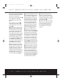
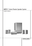
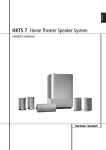
HKTS 7 OM
11/4/03
11:30 AM
Page 3
®
®
Power for the Digital Revolution.
HKTS 7
HOME THEATER SPEAKER SYSTEM
OWNER’S MANUAL
HKTS 7 OM
11/4/03
11:30 AM
Page 4
HKTS 7 HOME THEATER SPEAKER SYSTEM
3
4
4
5
7
7
8
9
9
10
11
12
13
13
13
14
15
Safety Information
Introduction
Included
SUB-TS7 Subwoofer Amplifier Panel Controls and Connections
Speaker Placement
Color-Coding System
Mounting Options
Speaker Connections
Speaker-Level Connection Guide
Dolby Digital or DTS (or Other Digital Surround Mode) Connection
Dolby Pro Logic (Non-Digital) – Line Level
Dolby Pro Logic (Non-Digital) – Speaker Level
Operation
Volume
Additional Bass Adjustments
Troubleshooting
Specifications
Typographical Conventions
In order to help you use this manual, certain conventions have been used.
EXAMPLE – (bold type) indicates a specific control or rear-panel connection on the SUB-TS7 subwoofer
EXAMPLE – (OCR type) indicates a control or switch position on the SUB-TS7 subwoofer
¡ – (number in a circle) indicates a rear-panel control or connection on the SUB-TS7 subwoofer
2
TABLE OF CONTENTS
HKTS 7 OM
11/4/03
11:30 AM
Page 5
SAFETY INFORMATION
Read First! Important Safety Precautions!
CAUTION
RISK OF ELECTRIC SHOCK
DO NOT OPEN
CAUTION: To prevent electric shock,
do not use this (polarized)
plug with an extension cord,
receptacle or other outlet
unless the blades can
be fully inserted to
prevent blade exposure.
The lightning flash with arrowhead symbol,
within an equilateral triangle, is intended to
alert the user to the presence of uninsulated
“dangerous voltage” within the product’s
enclosure that may be of sufficient magnitude to constitute a
risk of electric shock to persons.
The exclamation point within an equilateral
triangle is intended to alert the user to the
presence of important operating and
maintenance (servicing) instructions in the
literature accompanying the appliance.
1. Read these instructions.
2. Keep these instructions.
3. Heed all warnings.
4. Follow all instructions.
12. Use only with the cart, stand, tripod,
bracket or table specified by the manufacturer or sold with the apparatus.
When a cart is used, use caution when
moving the cart/apparatus combination to avoid injury
from tip-over.
13. Unplug this apparatus during lightning storms or
when unused for long periods of time.
14. Refer all servicing to qualified service personnel.
Servicing is required when the apparatus has been
damaged in any way, such as power-supply cord or
plug is damaged, liquid has been spilled or objects
have fallen into the apparatus, the apparatus has been
exposed to rain or moisture, does not operate normally, or has been dropped.
15. Do not use attachments not recommended by
the product manufacturer, as they may cause hazards.
16. This product should be operated only from the
type of power source indicated on the marking label.
If you are not sure of the type of power supply to
your home, consult your product dealer or local
power company. For products intended to operate
from battery power, or other sources, refer to the
operating instructions.
5. Do not use this apparatus near water.
6. Clean only with a dry cloth.
7. Do not block any ventilation openings. Install in
accordance with the manufacturer’s instructions.
8. Do not install near any heat sources such as radiators, heat registers, stoves or other apparatus (including amplifiers) that produce heat.
9. Do not defeat the safety purpose of the polarized
or grounding-type plug. A polarized plug has two
blades with one wider than the other. A groundingtype plug has two blades and a third grounding
prong. The wide blade or the third prong are provided
for your safety. If the provided plug does not fit into
your outlet, consult an electrician for replacement of
the obsolete outlet.
10. Protect the power cord from being walked on or
pinched, particularly at plugs, convenience receptacles
and the point where they exit from the apparatus.
11. Only use attachments/accessories specified by
the manufacturer.
17. If an outside antenna or cable system is connected
to the product, be sure the antenna or cable system
is grounded so as to provide some protection against
voltage surges and built-up static charges. Article 810
of the National Electrical Code, ANSI/NFPA 70, provides information with regard to proper grounding
of the mast and supporting structure, grounding of
the lead-in wire to an antenna discharge unit, size
of grounding conductors, location of antennadischarge unit, connection to grounding electrodes,
and requirements for the grounding electrode.
See Figure 1.
Figure 1.
Example of Antenna Grounding as per
National Electrical Code ANSI/NFPA 70
18. An outside antenna system should not be located
in the vicinity of overhead power lines or other electric
light or power circuits, or where it can fall into such
power lines or circuits. When installing an outside
antenna system, extreme care should be taken to
keep from touching such power lines or circuits, as
contact with them might be fatal.
19. Do not overload wall outlets, extension cords, or
integral convenience receptacles, as this can result in
a risk of fire or electric shock.
20. Never push objects of any kind into this product
through openings, as they may touch dangerous voltage points or short-out parts that could result in a fire
or electric shock. Never spill liquid of any kind on the
product.
21. Do not attempt to service this product yourself, as
opening or removing covers may expose you to dangerous voltage or other hazards. Refer all servicing to
qualified service personnel.
22. When replacement parts are required, be sure
the service technician has used replacement parts
specified by the manufacturer or that have the same
characteristics as the original part. Unauthorized substitutions may result in fire, electric shock or other
hazards.
23. Upon completion of any service or repairs to this
product, ask the service technician to perform safety
checks to determine that the product is in proper
operating condition.
24. The product should be mounted to a wall or
ceiling only as recommended by the manufacturer.
Antenna Lead-In Wire
Ground Clamp
Antenna Discharge Unit (NEC Section 810-20)
Grounding Conductors (NEC Section 810-21)
Electric Service Equipment
Ground Clamps
Power Service Grounding Electrode System
(NEC Art 250, Part H)
SAFETY INFORMATION
3
HKTS 7 OM
11/4/03
11:30 AM
Page 6
INTRODUCTION
Introduction
Thank you for purchasing the Harman Kardon
HKTS 7, with which you’re about to begin
many years of listening enjoyment. The
HKTS 7 has been custom-designed to
provide all the excitement and power of the
cinema experience in your own living room.
While sophisticated electronics and state-ofthe-art speaker components are hard at work
within the HKTS 7, hookup and operation
are simple. Color-keyed cables and connections, and simple controls make the HKTS 7
easy to use.
To obtain maximum enjoyment from your
new home theater speaker system, we urge
you to take a few minutes to read through
this manual. This will ensure that connections to your receiver or preamp/processor
and amplifier or other external devices are
made properly. In addition, a few minutes
spent learning the functions of the various
controls will enable you to take advantage
of all the power and refinement the HKTS 7
is able to deliver.
If you have any questions about this product, its installation or operation, please
contact your dealer, the best local source
of information.
Description and Features
The HKTS 7 is a six-piece home theater
speaker system that includes a 10-inch,
100-watt, bass-reflex powered subwoofer;
four identical, 2-way satellite speakers
for use in the left and right front and rear
speaker positions; a voice-matched,
dedicated, dual-driver center speaker; shelf
stands and wall-mount brackets for the
four satellites; and all of the speaker
cables you need to connect your speakers
to your receiver or preamp/processor and
amplifier. The speaker cables and speakers
all use a color-coding system to conform
to the CEA standard. The color-coding
system minimizes confusion, especially
when the HKTS 7 system is used with a
Harman Kardon receiver.
4
INTRODUCTION
The HKTS 7 subwoofer is easy to connect
to your system, since it’s equipped with a
special subwoofer input for use with equipment that has a dedicated subwoofer connection that carries a low-frequency output.
It also includes stereo speaker-level inputs
and outputs for connection to older
receivers and processors that do not have
a line-level subwoofer output. Other conveniences include a level control, high-cut
(low-pass) filter switch and phase switch for
fine-tuning bass response to suit your listening
environment and taste, and an efficient
switching system that senses the presence of
an audio signal and automatically switches
the unit from Standby mode to Active mode.
Shelf stands and wall-mount brackets are
included for the satellite speakers, and
optional HTFS 2 floor stands are available
separately from your Harman Kardon dealer.
Harman Kardon invented the high-fidelity
receiver fifty years ago. With state-of-the-art
features and time-honored circuit designs,
the HKTS 7 is a perfect complement to
a Harman Kardon receiver or any home
theater system.
■ Complete home theater speaker
system
■ Speakers are magnetically shielded
for placement near video monitors
■ Fully color-coded cables and
connections simplify setup
■ Both line- and speaker-level inputs
for use with most audio components
■ Subwoofer input offers superiorquality bass reproduction when used
with any digital audio system that
incorporates bass management or
programmable crossovers
One powered
subwoofer
Four satellites
for left, right
and surrounds,
with color-key
stickers (shown
with included shelf
stands attached)
Four wall-mount brackets
One 15' RCA cable for connection to subwoofer (purple)
Three 20' speaker cables for connection to front
satellites (red and white) and to center
speaker (green)
Included
One center channel speaker
Two 40' speaker cables for connection from
receiver to rear satellites (gray and blue)
HKTS 7 OM
11/4/03
11:30 AM
Page 7
SUB-TS7 SUBWOOFER AMPLIFIER PANEL CONTROLS AND CONNECTIONS
SUBWOOFER
LEVEL
SUB-TS7
For use with
HKTS 7 System
¡
FILTER
ON
™
MAX
MIN
OFF
C A U TIO N
£
R ISK OF ELEC TR IC SH O C K
D O NO T OPE N
ON
AUTO
PHASE
¢
∞
REVERSE
NORMAL
SUB
§
H
I
G
H
¶
•
ª
‚
L
R
LINE
LEVEL
IN
L
E
V
E
L
"WARNING: FOR CONTINUED PROTECTION AGAINST RISK OF FIRE,
REPLACE ONLY WITH SAME TYPE T 2.5A L/250 VOLT FUSE"
L
"AVERTISSEMENT: UTILISEZ UN FUSIBLE DE RECHANGE DE MEME
TYPE T 2.5A L/250V"
POWER
AC 120V~60Hz
R
OUT
IN
IMPORTANT: CONNECT STRIPED WIRE
TO RED ( ) SPEAKER TERMINAL.
¡ Subwoofer-Level Control
™ High-Cut (Low-Pass) Filter Switch
£ Music-Sense On/Off Switch
¢ Phase Switch
∞ Line-Level Subwoofer (SUB) Input
§ Line-Level Full-Range Inputs
¶ Speaker-Level Outputs
• Speaker-Level Inputs
ª Master Power Switch
‚ AC Power Cord
¡ Subwoofer-Level Control: Volume
may be adjusted using the SubwooferLevel Control. Turn the control clockwise
to increase the SUB-TS7’s volume, or
counterclockwise to decrease it.
inefficiency and distortion. Engage this filter
when using the Speaker-Level Inputs •,
or when using the Line-Level Full-Range
Inputs §, unless your receiver or processor
processes its line-level output using a lowpass filter. The filter has no effect when the
SUB Input ∞ is used.
place itself in the Standby mode, depending on
whether it is receiving an audio signal. When
this switch is placed in the ON position, the
SUB-TS7 will remain on, whether or not it is
receiving an audio signal.
™ High-Cut (Low-Pass) Filter Switch:
Placing this switch in the ON position activates circuitry that cuts out all audio input
signals above 120Hz. This allows the SUBTS7 to focus its power on reproducing the
low-frequency portion of the signal, avoiding
£ Music-Sense On/Off Switch: When
placed in the AUTO position, and when the
Master Power Switch ª is turned on, the
SUB-TS7 will automatically turn itself on or
An LED located on top of the SUB-TS7 indicates whether the SUB-TS7 is in the ON or
STANDBY state when used with the MusicSense On/Off Switch £ in the AUTO
position. The LED is lit blue to indicate that
the SUB-TS7 is receiving an audio signal
SUB-TS7 SUBWOOFER AMPLIFIER PANEL CONTROLS AND CONNECTIONS
5
HKTS 7 OM
11/4/03
11:30 AM
Page 8
SUB-TS7 SUBWOOFER AMPLIFIER PANEL CONTROLS AND CONNECTIONS
and is turned on, and the LED is lit amber to
indicate that no signal is being received and
the SUB-TS7 is in Standby mode.
When the Music-Sense On/Off Switch £
is in the ON position, the LED will be
lit blue, whether or not an audio signal is
present.
When the Master Power Switch ª is
turned off, the LED goes dark, no matter
which position the Music-Sense On/Off
Switch £ is in.
¢ Phase Switch: This switch determines
whether the SUB-TS7 subwoofer’s pistonlike action moves in and out in phase with
the main speakers. If the speakers were to
play out of phase, the sound waves produced by the subwoofer would be cancelled
out, reducing bass response. This phenomenon depends in part on the relative placement of the speakers in the room. In most
cases, the Phase Switch ¢ should be left
in the NORMAL position. However, it
does no harm to experiment with the Phase
Switch ¢, and you may leave it in the
position that maximizes bass response.
∞ Line-Level Subwoofer (SUB) Input:
Connect the subwoofer output of a receiver
with digital surround sound decoding, such
as Dolby* Digital or DTS®, to this input. This
input bypasses the SUB-TS7’s internal
crossover circuitry, and should only be used
with a filtered signal. If your receiver does not
have digital decoding, you should use the
Line-Level Full-Range Inputs § instead.
6
§ Line-Level Full-Range Inputs: Connect
the line-level subwoofer output or preamp output(s) of your receiver or amplifier to these
inputs. If your receiver does not have a separate subwoofer output, use a Y-adapter (not
supplied) to bridge the receiver’s preamp output to the main amp input for that channel,
and connect the long end of the adapter
to the corresponding line-level input on the
SUB-TS7. If your receiver has only a single
subwoofer output, you may connect it to
either the left or right line-level input on the
SUB-TS7, and no Y-adapter is needed.
ª Master Power Switch: Place this
switch in the “•” position to power-on the
SUB-TS7 subwoofer. The SUB-TS7 will then
be either in the Standby mode or completely
on, depending on the position of the MusicSense On/Off Switch £.
‚ AC Power Cord: Make sure to plug this
cord into an active, unswitched electrical outlet for proper operation of the SUB-TS7.
The cord should not be plugged into the
accessory outlets found on some audio
components.
¶ Speaker-Level Outputs: If you are
using the Speaker-Level Inputs • on the
SUB-TS7, you should connect these bindingpost terminals to your front left and right
speakers, remembering to maintain polarity
by connecting the (+) terminal on the SUBTS7 subwoofer to the (+) terminal on the
speaker, and the (–) terminal on the SUBTS7 subwoofer to the (–) terminal on the
speaker. If you are not using the SpeakerLevel Inputs •, then connect your front
left and right speakers directly to your receiver
or amplifier. See pages 9 through 12 for
further information on speaker connections.
• Speaker-Level Inputs: Connect these
binding-post terminals to the main left and
right speaker terminals of your receiver or
amplifier, if your receiver or amplifier does
not have a line-level subwoofer output.
Remember to maintain polarity by connecting
the (+) terminal on the receiver/amplifier to the
(+) terminal on the SUB-TS7 subwoofer, and
the (–) terminal on the receiver/amplifier to the
(–) terminal on the SUB-TS7 subwoofer.
SUB-TS7 SUBWOOFER AMPLIFIER PANEL CONTROLS AND CONNECTIONS
HKTS 7 OM
11/4/03
11:30 AM
Page 9
SPEAKER PLACEMENT
Color-Coding System
The HKTS 7 uses the channel color-coding
system established by the Consumer
Electronics Association to make setting up
your home theater speaker system as easy
as possible. Your system includes a set of
colored stickers that may be placed near
the speaker terminals of each of the four
satellite speakers according to the key below.
It doesn’t matter which satellite speaker is
used for any of the front or rear positions.
(The center speaker and powered subwoofer are already color-coded for you.)
Speaker
Position
Front Left
Front Right
Center
Surround Left
Surround Right
Subwoofer (LFE)
Sticker (or Terminal)
and Cable Color
White
Red
Green
Blue
Gray
Purple
Surround Speakers
Center Channel Speaker
Green
White
White
Green
Blue
The center channel speaker should be
placed slightly behind the front left and right
speakers, and no more than two feet above
or below the tweeters of the left and right
speakers. It is often convenient to set the
center speaker on top of the television set,
as shown in the drawing.
Subwoofer
White
Red Purple
Front Speakers
White
Red
The front speakers should be placed the
same distance from each other as they are
from the listening position. They should be
placed at about the same height from the
floor as the listeners’ ears will be.
Red
Red 0-2 ft.
The low-frequency material reproduced by
the subwoofer is mostly omnidirectional,
and this speaker may be placed in a convenient location in the room. However, the
maximum reproduction of bass will be
heard when the subwoofer is placed in a
corner along the same wall as the front
speakers. Experiment with subwoofer placement by temporarily placing the subwoofer
in the listening position and moving around
the room until the bass reproduction is
best. Place the subwoofer in that location.
Gray
5 – 6 ft.
The two surround speakers should be
placed slightly behind the listening position
and, ideally, should face each other and be
at a level higher than the listeners’ ears.
If that is not possible, they may be placed
on a wall behind the listening position,
facing forward. The surround speakers
should not call attention to themselves.
Experiment with their placement until you
hear a diffuse, ambient sound accompanying
the main-program material heard in the
front speakers.
SPEAKER PLACEMENT
7
HKTS 7 OM
11/4/03
11:30 AM
Page 10
MOUNTING OPTIONS
Satellites and Surrounds
They may be wallmounted using the
supplied brackets.
The satellite speakers may
be placed on a shelf.
Wall-Mounting
Unscrew the bolt that attaches the black
shelf stand to the bottom of the speaker.
Store the stand and bolt in a safe place
in case they are needed for a future
installation.
Wires to Speaker
Terminal Cover
Wall Bracket
Wall Plate
Mount the wallRemove
bracket attachment
Stand
plate on the wall in
the desired location. 15mm
or 1/2"
If possible, position
the speakers so that
the mounting screws
(not included; use size #8) may be
installed directly into a wooden wall stud.
If that is not possible, use optional wall
anchors that are rated to support at least
twenty-five pounds. The customer is
responsible for proper selection and use
of mounting hardware, available through
hardware stores, to properly and safely
wall-mount the speakers.
Referring to the speaker connection instructions on pages 9 through 12, thread the
appropriate speaker cable through the opening in the bottom of the attachment plate,
and then through the back of the bracket as
shown in the diagram. The bracket has two
8
MOUNTING OPTIONS
Overhead
View
Wire
From
Wall
Plate
openings on top: a round screw hole, and an
arc-shaped opening in front of it. The speaker
cable should be threaded through the arcshaped opening, not the screw hole.
Attach the bracket to the wall plate by inserting the tab at the top of the attachment plate
into the slot on top of the bracket and snapping the bracket onto the attachment plate.
Thread the cable through the round opening
in the terminal cover, and then insert the
speaker wires into the terminals on the
underside of the speaker, remembering to
observe the correct polarity (see page 9).
Place the terminal cover over the opening
on the underside of the speaker so that it fits
flush against the speaker and covers the terminals, with its round opening exposing the
threaded insert. The bracket fits through the
round opening in the terminal cover.
Insert the supplied bracket bolt up through
the bottom of the bracket and terminal
cover, and screw it into the threaded insert
on the underside of the speaker. The bolt
should be snug, but not so tight as to
prevent the bracket from pivoting.
The wall-mounted speaker may be pivoted
from side to side; however, the bracket is
not designed to tilt up or down, and
attempting to tilt it will damage the bracket
and possibly the wall, which would not be
covered by your warranty.
Wall
23mm
or 3/4"
(M6–1.25P
or 1/4"–20)
HKTS 7 OM
11/4/03
11:30 AM
Page 11
SPEAKER CONNECTIONS
Speaker-Level Connection Guide
IMPORTANT NOTE: Before making speaker
connections, be certain that your receiver or
audio power amplifier is turned off and
preferably unplugged from its AC power
source. The SUB-TS7 subwoofer should
not be connected to an AC power source
until all speaker wire connections have
been made.
Speakers and electronics terminals have
corresponding (+) and (–) terminals. Most
manufacturers of speakers and electronics,
including Harman Kardon, use red to denote
the (+) terminal and black for the (–)
terminal.
connected to the correct terminals on your
receiver or amplifier.
The (+) lead of the speaker wire is indicated
with a stripe and has the colored band corresponding to the speaker’s position. It is
important to connect all speakers identically:
(+) on the speaker to (+) on the amplifier
and (–) on the speaker to (–) on the amplifier. Wiring “out of phase” results in thin
sound, weak bass and a poor stereo image.
With the advent of multichannel surround
sound systems, connecting all of the speakers
in your system with the correct polarity
remains equally important in order to preserve
the proper ambience and directionality of the
program material.
To connect the supplied speaker wires to
the satellite and center speaker terminals
located on the bottom of each speaker,
press the red or black tab, insert the bare
end of the wire into the hole, and release
the tab. Gently tug on the wire to make sure
that it is fully inserted.
Newer Harman Kardon receivers conform to
the CEA standard and therefore use a color
other than red or black for the (+) terminal
to indicate some speaker positions: e.g.,
surround left. Although the HKTS 7 system
has red and black collars on the individual
speaker terminals to denote the positive and
negative connections, your system includes
a colored band on the positive lead at both
ends of every speaker cable and a matching
colored sticker for each of the four satellite
speakers, conforming to the key on page 7.
The center speaker has a green (+) terminal,
and the subwoofer has a purple SUB input
jack. This system is intended to help you
ensure that the speaker in each location is
For the best performance, Harman Kardon
recommends that the subwoofer be
connected using either the Line-Level
Subwoofer (SUB) Input ∞ or the LineLevel Full-Range Inputs §. However,
if the application requires the use of the
speaker-level connections for the subwoofer,
unscrew the binding-post collar until the
pass-through hole in the center post is visible under the collar. Insert the bare end of
the wire through this hole; then screw the
collar down until the connection is tight. The
hole in the center of each collar is intended
for use with banana-type connectors.
SPEAKER CONNECTIONS
9
HKTS 7 OM
11/4/03
11:30 AM
Page 12
SPEAKER CONNECTIONS
Dolby* Digital or DTS® (or Other
Digital Surround Mode) Connection
USE THIS INSTALLATION METHOD FOR
DOLBY DIGITAL, DTS OR OTHER DIGITAL
SURROUND PROCESSORS:
Center
–
+
Front
Left
–
+
SUB-TS7 Subwoofer
Use the line-level input jack marked SUB
∞ for the Low-Frequency Effects channel.
Connect this jack to the subwoofer output
or LFE output on your receiver or amplifier.
Connect each speaker to the corresponding
speaker terminals on your receiver or
amplifier.
LINE LEVEL IN
SUB
Make sure you’ve configured your surround
sound processor for “Subwoofer On.” The
front left, front right, center and surround
speakers should all be set to “Small.”
L
Front
Right
SUB/LFE
Out
Surround
Left
Surround
Left
–
+
SPEAKER CONNECTIONS
R
Front
Left
When all connections have been made, plug
the AC power cord on the subwoofer into
an AC outlet.
10
Front
Right
–
+
Center
Receiver
Surround
Right
Surround
Right
–
+
HKTS 7 OM
11/4/03
11:30 AM
Page 13
SPEAKER CONNECTIONS
Dolby Pro Logic*
(Non-Digital) – Line Level
USE THIS INSTALLATION METHOD FOR
DOLBY PRO LOGIC APPLICATIONS (NOT
DOLBY DIGITAL, DTS OR OTHER DIGITAL
PROCESSING), WHERE THE RECEIVER/
PROCESSOR IS EQUIPPED WITH A SUBWOOFER OUTPUT, OR A VOLUMECONTROLLED PREAMP (LINE-) LEVEL
OUTPUT:
Use the supplied RCA-type interconnect
cable to connect the line-level subwoofer
output on your receiver or amplifier to either
the left or right Line-Level Full-Range
Input § on the SUB-TS7 subwoofer. Use
both the left and right inputs on the subwoofer if your receiver or processor has
both left and right line-level outputs. In that
case, you will need to supply a second
interconnect cable.
If your receiver is equipped with line-level outputs but does not have a separate subwoofer
output, use a Y-adapter (not supplied) to
bridge the receiver’s preamp output to the
main amp input for that channel, and connect
the long end of the adapter to the corresponding line-level input on the SUB-TS7.
Center
–
+
Front
Left
–
+
Front
Right
–
+
SUB-TS7
Subwoofer
Line-Level
R
L
Front
Left
Front
Right
SUB/LFE
Out
Surround
Left
Surround
Left
–
+
Center
Receiver
Surround
Right
Surround
Right
–
+
IMPORTANT: Do not use the SUB Input
∞ on the subwoofer with Dolby Pro Logic
processors.
If your receiver/processor has a built-in lowpass-crossover filter for the subwoofer output, you may use the SUB Input ∞ to
bypass the subwoofer’s internal crossover.
Connect each speaker to the corresponding
speaker terminals on your receiver or amplifier.
Make sure that you have configured your
surround sound processor for “Subwoofer
On.” The front left, front right, center and
surround speakers should all be set to
“Small.”
When all connections have been made, plug
the AC power cord on the subwoofer into
an AC outlet.
SPEAKER CONNECTIONS
11
HKTS 7 OM
11/4/03
11:30 AM
Page 14
SPEAKER CONNECTIONS
Dolby Pro Logic
(Non-Digital) – Speaker Level
USE THIS INSTALLATION METHOD FOR
DOLBY PRO LOGIC APPLICATIONS (NOT
DOLBY DIGITAL, DTS OR OTHER DIGITAL
PROCESSING), WHERE THE RECEIVER/
PROCESSOR DOES NOT HAVE A SUBWOOFER OUTPUT, OR A VOLUMECONTROLLED PREAMP (LINE-) LEVEL
OUTPUT:
Center
Front
Left
–
–
+
–
H
I
G
H
L
E
V
E
L
Connect your receiver or amplifier’s center
and surround left and right speaker terminals to the corresponding terminals on the
back of your center, and surround left and
right speakers.
L
R
Receiver
Front Left
When all connections have been made,
plug the AC power cord on the subwoofer
into an AC outlet.
Surround Left
Surround
Left
–
SPEAKER CONNECTIONS
+
SUB-TS7
Subwoofer
Connect your receiver or amplifier’s front
left and right speaker terminals to the left
and right Speaker-Level Input • terminals on the SUB-TS7 subwoofer that are
marked “High Level In.” Connect the left and
right Speaker-Level Output ¶ terminals
on the SUB-TS7 subwoofer that are marked
“High Level Out” to the corresponding terminals on the back of your front left and right
speakers.
12
Front
Right
+
+
Center
Front Right
Surround Right
Surround
Right
–
+
HKTS 7 OM
11/4/03
11:30 AM
Page 15
OPERATION
Move the Master Power Switch ª
(marked Power) to the “•” (On) position.
The SUB-TS7 subwoofer will automatically
turn itself on or go into Standby mode,
depending on whether or not a signal is
being sent to it by your receiver or surround
processor, and provided that the MusicSense On/Off Switch £ is moved down
so that it is in the AUTO position.
When your receiver or amplifier is off, or is
not sending program material to the subwoofer, the subwoofer will be in Standby
mode and the LED Indicator on the top of
the subwoofer will turn amber. When the
subwoofer senses an audio signal, it will
automatically turn itself on and the LED
Indicator will turn blue. If the subwoofer does
not sense a signal after approximately twenty
minutes, it will automatically go into Standby
mode.
When the Music-Sense On/Off Switch £
is switched to the ON position, the subwoofer will remain on, whether or not
program material is playing, and the LED
Indicator will remain lit blue.
If you’ll be away from home for an extended
period of time, or if the subwoofer will not be
used, switch the Master Power Switch ª
to the OFF position.
Additional Bass Adjustments
Volume
Volume can be adjusted using the
Subwoofer-Level Control ¡, as
shown. Turn the control knob clockwise
to increase the volume of the subwoofer,
and counterclockwise to decrease the
subwoofer’s volume.
Subwoofer
Level
MIN
MAX
Subwoofer
Level
MIN
MAX
In addition to the volume adjustments
described above, the SUB-TS7 subwoofer
includes a Phase Switch ¢ and a Filter
Switch ™ that can be used to adjust the
bass response to suit your listening environment or taste.
In most situations, the Phase Switch ¢
should be left in the NORMAL position.
If you suspect that the subwoofer is playing
out of phase with the other speakers, which
would tend to diminish bass response, try
placing this switch in the REVERSE
position. There is no harm in experimenting,
and you may return the switch to the
NORMAL position at any time. If you
rearrange your room and reposition the
speakers, it would be a good idea to check
whether they are in phase by flipping this
switch.
The High-Cut (Low-Pass) Filter Switch
™ limits the frequencies of the audio signal
inputted to the subwoofer to the low frequencies that the subwoofer reproduces
best. This allows the subwoofer to perform
more efficiently, and with superior bass
reproduction, minimizing distortion that might
occur if the subwoofer attempted to reproduce higher frequencies. This switch should
be left in the ON position, except:
1. When the SUB Input ∞ is being used,
in which case it has no effect, or
2. When the Speaker-Level Inputs • or
the Line-Level Full-Range Inputs § are
being used with a crossover or filter aboard
the receiver or processor.
In these two circumstances, place the switch
in the OFF position.
OPERATION
13
HKTS 7 OM
11/4/03
11:30 AM
Page 16
TROUBLESHOOTING
SYMPTOM
SOLUTION
If there is no sound from
any of the speakers:
• Check that receiver/amplifier is on and a source is playing.
• Check that the powered subwoofer is plugged in and its Master Power Switch ª is switched on to the “•” position.
• Check all wires and connections between receiver/amplifier and speakers. Make sure all wires are connected.
Make sure none of the speaker wires are frayed, cut, punctured, or touching other wires.
• Review proper operation of your receiver/amplifier.
If there is no sound coming • Check the “Balance” control on your receiver/amplifier.
from one speaker:
• Check all wires and connections between receiver/amplifier and speakers. Make sure all wires are connected.
Make sure none of the speaker wires are frayed, cut or punctured, and that no wires are touching each other.
• In Dolby Digital or DTS mode, make sure that the receiver/processor is configured so that the speaker in question is enabled.
• Turn off all electronics and switch the speaker in question with one of the other speakers that is working correctly. Turn
everything back on, and determine whether the problem is in the same place: i.e., the speaker that was working previously
now has no sound and the speaker that was not working now sounds fine; or whether it has moved: i.e., the speaker that
was not working still has no sound and the speaker that was working is still fine. If the problem is in the same place, the
source of the problem is most likely with your receiver or amplifier, and you should consult the owner’s manual for that product
for further information. If the problem has followed the speaker, consult your dealer for further assistance or, if that is not
possible, visit our Web site at www.harmankardon.com for further information.
If there is no sound from
the center speaker:
• Check all wires and connections between receiver/amplifier and speaker. Make sure all wires are connected.
Make sure none of the speaker wires are frayed, ccut, punctured, or touching other wires.
• If your receiver/processor is set in Dolby Pro Logic mode, make sure the center speaker is not in phantom mode.
• If your receiver/processor is set in Dolby Digital or DTS mode, make sure the receiver/processor is configured so that
the center speaker is enabled.
If the system plays at low
volumes but shuts off as
volume is increased:
• Check all wires and connections between receiver/amplifier and speakers. Make sure all wires are connected.
Make sure none of the speaker wires are frayed, cut, punctured, or touching other wires.
• If more than one pair of main speakers is being used, check the minimum impedance requirements of your receiver/amplifier.
If there is low (or no) bass • Make sure the SUB ¡ or Line-Level Inputs § of the SUB-TS7 subwoofer and SUB or LFE output of your receiver
output:
or amplifier are properly connected by the RCA-type interconnect cable.
• If you are using the SUB-TS7’s Speaker-Level Inputs •, check your speaker cables to make sure they are all
connected; that none of the wires are frayed, cut, punctured, or touching other wires; and that you have maintained the
correct polarity by connecting positive terminals to positive terminals, and negative terminals to negative terminals.
• Make sure the subwoofer is plugged into an active electrical outlet and its Master Power Switch ª is
switched on to the “•” position.
• Check the speaker setup (bass management) settings in your A/V receiver or processor to make certain that the front,
center and surround speakers are configured for “Small,” and that the subwoofer is set for “Yes” or “On.”
If there is no sound from
the surround speakers:
14
• Check all wires and connections between receiver/amplifier and speakers. Make sure all wires are connected. Make sure
none of the speaker wires are frayed, cut, punctured, or touching other wires.
• Review proper operation of your receiver/processor and its surround sound features.
• Make sure the movie or TV show you are watching is recorded in a surround sound mode. If it is not, check to see
whether your receiver/processor has other surround modes you may use.
• In Dolby Digital or DTS mode, make sure your receiver/processor is configured so that the surround speakers are enabled.
• Review the operation of your DVD player and the jacket of your DVD to make sure that the DVD features the desired
Dolby Digital or DTS mode, and that you have properly selected that mode using both the DVD player’s menu
and the DVD disc’s menu.
TROUBLESHOOTING
HKTS 7 OM
11/4/03
11:30 AM
Page 17
SPECIFICATIONS
HKTS 7 System
Frequency Response
35Hz – 20kHz (–6dB)
SAT-TS7
Satellites
Recommended Power
10 – 80 Watts
Impedance
8 Ohms nominal
Sensitivity
86dB @ 1 Watt/1 meter
Tweeter
One 1/2" dome, video-shielded
Midrange
One 3" driver, video-shielded
CEN-TS7
Center
SUB-TS7
Subwoofer
Recommended Power
10 – 80 Watts
Amplifier
100 Watts RMS
Impedance
8 Ohms nominal
Bass
10" Woofer, bass-reflex enclosure
Sensitivity
86dB @ 1 Watt/1 meter
Dimensions (H x W x D)
18-7/8" x 13-3/8" x 13-3/8"
479mm x 340mm x 340mm
Tweeter
One 3/4" dome, video-shielded
Midrange
Dual 3" drivers, video-shielded
Weight
33 lb/15kg
Dimensions (H x W x D)
4" x 9-1/2" x 3-5/8"
102mm x 241mm x 92mm
Weight
2.2 lb/1kg
Dimensions (H x W x D)
6-9/16" x 3-15/16" x 3-5/8"
167mm x 100mm x 92mm
Weight
1.4 lb/0.6kg
All features and specifications are subject to change without notice.
Harman Kardon and Power for the Digital Revolution are registered trademarks
of Harman International Industries, Incorporated.
* Trademarks of Dolby Laboratories.
DTS is a registered trademark of Digital Theater Systems, Inc.
SPECIFICATIONS
15
HKTS 7 OM
11/4/03
11:30 AM
Page 2
®
®
250 Crossways Park Drive, Woodbury, New York 11797
516.255.HKHK (4545) Fax: 516.682.3523
© 2003 Harman International Industries, Incorporated
Printed 10/03
Part No. 406-000-00980