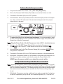
1
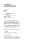
21 Gallon, 230 V~,
Cast Iron VERTICAL
AIR COMPRESSOR
93271
Set up and Operating Instructions
Distributed exclusively by Harbor Freight Tools®.
3491 Mission Oaks Blvd., Camarillo, CA 93011
Visit our website at: http://www.harborfreight.com
Read this material before using this product.
Failure to do so can result in serious injury.
Save this manual.
Copyright© 2005 by Harbor Freight Tools®. All rights reserved. No portion of this manual or any artwork
contained herein may be reproduced in any shape or form without the express written consent of
Harbor Freight Tools. Diagrams within this manual may not be drawn proportionally. Due to continuing
improvements, actual product may differ slightly from the product described herein. Tools required for
assembly and service may not be included.
For technical questions or replacement parts, please call 1-800-444-3353.
Manual revised 08j
SPECIFICATIONS
Maximum Air Pressure
Air Tank Capacity
Air Flow Capacity
Electrical Requirements
Pump Stage
Air Outlet Size
Shipping Weight
Power Cord
115 PSI with Auto Shut-Off
21 Gallons
3.5 CFM at 90 PSI
8.8 CFM at 40 PSI
230 V~ / 60 Hz / 7 A / 1 Phase
3 HP rated
Single
1/4” - 18 NPT
152 Pounds
10’ - Electrical Plug Sold Separately
SAVE THIS MANUAL
You will need this manual for the safety warnings and precautions, assembly,
operating, inspection, maintenance and cleaning procedures, parts list and assembly
diagram. Keep your invoice with this manual. Write the invoice number on the inside
of the front cover. Keep this manual and invoice in a safe and dry place for future reference.
GENERAL SAFETY WARNINGS AND PRECAUTIONS
1.
KEEP WORK AREA CLEAN AND DRY. Cluttered, damp, or wet work areas invite
injuries.
2.
KEEP CHILDREN AWAY FROM WORK AREA. Do not allow children to handle
this product.
3.
STORE IDLE EQUIPMENT. When not in use, tools and equipment should be
stored in a dry location to inhibit rust. Always lock up tools and equipment, and
keep out of reach of children.
4.
DO NOT USE THIS PRODUCT IF UNDER THE INFLUENCE OF ALCOHOL OR
DRUGS. Read warning labels on prescriptions to determine if your judgement or
reflexes are impaired while taking drugs. If there is any doubt, do not attempt to
use this product.
5.
USE EYE, HAND, AND HEARING PROTECTION. Wear ANSI approved safety
impact goggles, hearing protection, and heavy-duty work gloves when using this
product.
6.
DRESS SAFELY. Do not wear loose clothing or jewelry, as they can become
caught in moving parts. Wear a protective hair covering to prevent long hair from
becoming caught in moving parts. If wearing a long-sleeve shirt, roll sleeves up
above elbows.
7.
DO NOT OVERREACH. Keep proper footing and balance at all times to prevent
tripping, falling, back injury, etcetera.
REV 05j; 07f; 09a
SKU 93271
For technical questions, please call 1-800-444-3353.
PAGE 2
8.
INDUSTRIAL APPLICATIONS MUST FOLLOW OSHA REQUIREMENTS.
9.
STAY ALERT. Watch what you are doing at all times. Use common sense. Do
not use this product when you are tired or distracted from the job at hand.
10. CHECK FOR DAMAGED PARTS. Before using this product, carefully check that
it will operate properly and perform its intended function. Check for damaged parts
and any other conditions that may affect the operation of this product. Replace or
repair damaged or worn parts immediately.
11. REPLACEMENT PARTS AND ACCESSORIES: When servicing, use only identical replacement parts. Only use accessories intended for use with this product.
Approved accessories are available from Harbor Freight Tools.
12. MAINTAIN THIS PRODUCT WITH CARE. Keep this product clean and dry for
better and safer performance.
13. MAINTENANCE: For your safety, service and maintenance should be performed
regularly by a qualified technician.
14. USE THE RIGHT TOOL FOR THE JOB. Do not attempt to force a small tool or
attachment to do the work of a larger industrial tool. There are certain applications
for which this tool was designed. It will do the job better and more safely at the
rate for which it was intended. Do not modify this tool, and do not use this tool for
a purpose for which it was not intended.
15. The warnings, precautions, and instructions discussed in this manual cannot cover
all possible conditions and situations that may occur. The operator must understand that common sense and caution are factors, which cannot be built into this
product, but must be supplied by the operator.
SPECIFIC PRODUCT WARNINGS AND PRECAUTIONS
1.
CAUTION: Fill the Air Compressor with a premium quality, 30-weight, non-detergent oil before each use. Running the Air Compressor with no oil or low oil will
cause damage to the equipment.
Note: The oil reservoir has an optimal capacity of 30 ounces of oil.
2.
MAKE SURE ALL TOOLS AND EQUIPMENT USED WITH THE AIR COMPRESSOR ARE RATED TO THE APPROPRIATE CAPACITY. Do not use any tool or
equipment that does not operate at or above the PSI that the compressor’s regulator is set to.
3.
DRAIN AIR COMPRESSOR EVERY DAY. Do not allow moisture to build up inside
the Air Compressor. (See “INSPECTION, MAINTENANCE, AND CLEANING”
section of this manual.)
4.
MAINTAIN A SAFE WORKING ENVIRONMENT. Keep the work area well lit.
Make sure there is adequate surrounding workspace. Always keep the work area
SKU 93271
For technical questions, please call 1-800-444-3353.
PAGE 3
free of obstructions, grease, oil, trash, and other debris. Do not use the Air Compressor in areas near flammable chemicals, dusts, and vapors.
5.
AVOID INJURY: Never direct the pressurized air stream at people or animals.
6.
DO NOT ALTER OR REMOVE THE FACTORY SEALED PRESSURE RELEASE
VALVE (5A). (See Assy. Diagram A.)
7.
DO NOT OPEN THE WATER DRAIN VALVE (10A) SO THAT MORE THAN
FOUR THREADS ARE SHOWING. (See Assy. Diagram A.)
8.
An extension cord must never be used with this item. Connecting
this item to an outlet through an extension cord may cause electrical
damage to the motor and could present a fire hazard. Longer air
hoses are typically safer and more effective than extension cords.
9.
This unit requires a 230 V~, UL listed, twistlock plug (sold Separately) to be installed by a qualified electrician before setup
or use.
10. THIS COMPRESSOR MAY REQUIRE A DEDICATED ELECTRICAL CIRCUIT AS
THE AMPERAGE DRAW UNDER FULL LOAD COMBINED WITH USE OF ANY
OTHER ITEM MAY OVERLOAD YOUR CIRCUIT.
11. WARNING: This product contains or produces a chemical known to the State of
California to cause cancer and birth defects (or other reproductive harm).
(California Health & Safety Code § 25249.5, et seq.)
12. People with pacemakers should consult their physician(s) before use. Electromagnetic fields in close proximity to heart pacemaker could cause pacemaker interference or pacemaker failure.
REV 07f
SKU 93271
For technical questions, please call 1-800-444-3353.
PAGE 4
UNPACKING
When unpacking, make sure the item is intact and undamaged. If any parts are
missing or broken, please call Harbor Freight Tools at the number shown on the cover of
this manual as soon as possible.
Find the bag/box that contains all hardware for mounting the parts that are shipped
detached.
Assembly
Before use, thread the Muffler/Air Filter (7A) assembly into the Cylinder Case (2B).
Operation
Note: For additional references to the parts listed below, refer to the Assembly Diagrams on pages 10, and 11.
To Check The Oil Level:
Oil Breather (14B)
Front Cover (18B)
Oil Window (20B)
FIGURE A
1.
The Oil Window (20B) is used to determine if oil is needed. The oil level should
always be at the maximum level (red line on the Oil Window). (See Figure A, and
Assy. Diagram B.)
2.
Unscrew (do not pull) the Oil Breather (14B) out. (See Figure A.)
3.
If necessary, add a premium quality, 30-weight, non-detergent oil into the Oil Fill
Hole until the level of oil reaches the maximum level as indicated on the Oil Window (20B). The optimal capacity of the oil reservoir is 30 ounces. Do not overfill.
Then thread the Oil Breather back into the Oil Fill Hole, being careful not to strip
the plastic threads.
REV 08l
SKU 93271
For technical questions, please call 1-800-444-3353.
PAGE 5
To Turn The Air Compressor On:
1.
Fully close the Water Drain Valve (10A). (See Assy. Diagram A.)
2.
Pull on the Pressure Relief Valve (5A) briefly to ensure that it does not stick.
3.
Turn the Air Flow Valve (6A) to its “OFF” position.
4.
Connect the air hose (not provided) to the Air Flow Valve (6A) of the Air Compressor. Then, connect the other end of the air hose to the pneumatic tool (not provided) that is to be used.
5.
To extend the life of your air tools and equipment, it is recommended to install
an oiler and water filter in series (available from Harbor Freight Tools) with the Air
Output Line of the Air Compressor.
Note: Plug the Power Cord of the Air Compressor into a 230 V~ electrical source.
6.
Pull up on the “ON/OFF” Power Switch (1A) to turn the Air Compressor on.
(Push down on the “ON/OFF” Power Switch to turn the Air Compressor off.)
7.
Allow sufficient time for the Tank Pressure Gauge (4A) to indicate 80 PSI before
using the Air Compressor.
8.
Turn the Air Flow Valve (6A) to its “ON” position to allow air to the pneumatic tool.
9.
With the Air Compressor turned on, the operation is automatic and under the control of the automatic switches inside the box under the Power Switch (1A).
Never open the power switch box or adjust the controls within.
To Adjust The Air Output To The Pneumatic Tool:
Note: When adjusting the air pressure being forwarded to the pneumatic tool, you will
need to compare the pressure readings of both the Tank Pressure Gauge (3A) and
the Tool Pressure Gauge (4A). The reading on the Tank Pressure Gauge dictates
the maximum/minimum air pressure at which the Tool Pressure Gauge may also
be set.
1.
With the Air Compressor running, and the air hose and pneumatic tool hooked up
to the Air Compressor, pull up on the Tool Pressure Adjuster (2A). Turn the Tool
SKU 93271
For technical questions, please call 1-800-444-3353.
PAGE 6
Pressure Adjuster clockwise to increase the air output to the tool, up to the working air pressure (115 PSI) as indicated on the Tank Pressure Gauge (3A). Never
exceed the maximum PSI for the tool being used or any component of the air
system.
2.
Turn the Tool Pressure Adjuster (2A) counterclockwise to decrease the air output
to the tool.
To Use The Tank Pressure Relief Valve:
1.
The Tank Pressure Relief Valve Ring (5A) is used when decompression is needed
quickly and efficiently. It is also designed to release automatically if the compressor pressurizes up to or beyond it’s safe limit.
2.
To decompress the Air Tank (9A) pressure, press the “ON/OFF” Power Switch (1A)
down to turn off the Air Compressor.
3.
Pull out on the Tank Pressure Relief Valve Ring (5A) to immediately release air
pressure in the Air Tank (9A).
To Empty Moisture From The Tank:
1.
The Water Drain Valve (10A) is located underneath the Air Tank (9A), and should
be used daily to release all trapped moisture through this valve. If this is not done,
condensation may cause Air Tank corrosion. (See Assy. Diagram A.)
WARNING: Do not open the Water Drain Valve (10A) so that more than four threads are
showing.
2.
Push down on the “ON/OFF” Power Switch (1A) to turn off the Air Compressor.
Then, unplug the Air Compressor’s Power Cord from the electrical outlet.
3.
You may wish to lay a pan under the drain to collect the dirty water trapped within.
Slowly and carefully unscrew (no more than four threads) the Water Drain Valve
(10A) until the compressed air and condensation begins to be released from the Air
Tank (9A). Allow sufficient time for all of the air and condensation to escape from
the Air Tank. Then, firmly retighten the Water Drain Valve.
IMPORTANT!
If the motor stops unexpectedly, the overload breaker may have
sensed an over-current condition, and stopped the motor to protect it. If this occurs, shut off the pressure switch and wait at least 5 minutes. Release the air pressure
in the tank to ease restarting. Then press the breaker button to reset it, and turn on the
pressure switch. To help prevent this, ensure that this compressor is set up on a dedicated circuit (one with no other equipment running on it), and that the distance from the
compressor to the circuit breaker panel is as short as possible. Extension cords should
not be used, and the outlet should not be far from the panel.
SKU 93271
For technical questions, please call 1-800-444-3353.
PAGE 7
INSPECTION, MAINTENANCE, AND CLEANING
WARNING: Disconnect the Air Compressor from its electrical supply source before performing any inspection, maintenance, or cleaning.
1.
BEFORE EACH USE, inspect the general condition of the Air Compressor. Check
all air fittings for leaks. Check for loose screws, misalignment or binding of moving parts, cracked or broken parts, damaged power cord and plug, and any other
condition that may affect the safe operation of this tool. If abnormal noise or vibration occurs, immediately disconnect the Air Compressor from its electrical supply
source and have the problem corrected before further use.
Do not use damaged equipment.
2.
DAILY: Check the Air Compressor oil level. If necessary, fill with a premium quality, 30-weight, non-detergent oil. NOTE: When checking the oil level, make sure to
unscrew (do not pull) the Oil Breather (14B). (See Assy. Diagram B.)
3.
DAILY: Purge the Air Tank (9A) of all air and moisture to prevent corrosion. To do
so, slowly and carefully unscrew (no more than four threads) the Water Drain Valve
(10A) until the compressed air and condensation begins to be released from the Air
Tank. Allow sufficient time for all of the air and condensation to escape from the Air
Tank. Then, firmly retighten the Water Drain Valve. (See Assy. Diagram A.)
4.
EVERY 100 HOURS OF USE: Clean the Air Filter (7A) with a mild solvent. Then,
dry and reattach the Air Filter. NOTE: Replace the Air Filter if it is too dirty to properly clean. (See Assy. Diagram A.)
5.
EVERY 500 HOURS OR 12 MONTHS: Drain and replace the old oil with new, premium quality, 30-weight, non-detergent oil. When the Oil Drain (16A) is removed,
the old oil needs to be collected and disposed of in full accord with all applicable
waste disposal ordinances.
6.
TO CLEAN: wipe with a damp cloth, using a mild detergent or mild solvent.
7.
WHEN STORING: Keep the Air Compressor in a clean, dry location.
PLEASE READ THE FOLLOWING CAREFULLY
THE MANUFACTURER AND/OR DISTRIBUTOR HAS PROVIDED THE PARTS DIAGRAM IN THIS
MANUAL AS A REFERENCE TOOL ONLY. NEITHER THE MANUFACTURER NOR DISTRIBUTOR
MAKES ANY REPRESENTATION OR WARRANTY OF ANY KIND TO THE BUYER THAT HE OR SHE
IS QUALIFIED TO MAKE ANY REPAIRS TO THE PRODUCT OR THAT HE OR SHE IS QUALIFIED TO
REPLACE ANY PARTS OF THE PRODUCT. IN FACT, THE MANUFACTURER AND/OR DISTRIBUTOR
EXPRESSLY STATES THAT ALL REPAIRS AND PARTS REPLACEMENTS SHOULD BE UNDERTAKEN
BY CERTIFIED AND LICENSED TECHNICIANS AND NOT BY THE BUYER. THE BUYER ASSUMES
ALL RISK AND LIABILITY ARISING OUT OF HIS OR HER REPAIRS TO THE ORIGINAL PRODUCT OR
REPLACEMENT PARTS THERETO, OR ARISING OUT OF HIS OR HER INSTALLATION OF REPLACEMENT PARTS THERETO.
SKU 93271
For technical questions, please call 1-800-444-3353.
PAGE 8
PARTS LIST A / ASSEMBLY DIAGRAM
Part
1A
2A
3A
4A
5A
6A
7A
9A
10A
11A
Description
ON/OFF Power Switch
Tool Pressure Adjuster
Tank Pressure Gauge
Tool Pressure Gauge
Pressure Release Valve
Air Flow Valve
Air Filter
Air Tank
Water Drain Valve
Quick Release Coupler
Qty.
Part
1
1
1
1
1
1
1
1
1
1
16A
12A
13A
14A
15A
16A
17A
18A
19A
20A
Description
Rubber Wheel
Washer
Nut
Fitting
Oil Drain Plug with Gasket
Foot
Unloader Valve
Polyurethane Unloader Tube
Copper Air Tube
Qty.
2
2
2
1
1
2
1
1
1
(Rear View with motor cover removed.)
7A
1A
5A
2A
3A
4A
20A
6A
18A
19A
15A
9A
11A
12A
10A
13A
14A
17A
SKU 93271
For technical questions, please call 1-800-444-3353.
PAGE 9
PARTS LIST B / ASSEMBLY DIAGRAM B
Part
1B
2B
3B
4B
5B
6B
7B
8B
9B
10B
11B
12B*
13B
14B
15B
16B
17B
18B
19B
Description
Bolt
Cylinder Case
Gasket
Valve Seat
Gasket
Cylinder
Compression Ring
Oil Scraping Ring
Piston
Gasket
Piston Pin
End Cover
Crankshaft Retainer
Oil Breather
Connecting Rod
Gasket
Bolt
Front Cover
Gasket
Qty.
4
1
1
1
1
1
2
1
1
1
1
1
2
1
1
1
6
1
1
Part
Description
Qty.
20B Oil Window
1
21B Crankshaft Bolt
1
22B Crankshaft
1
23B Crankshaft Case
1
24B* Stator
1
25B* Bearing
2
26B* Armature
1
27B Capacitor
1
28B Radiating Fan Wheel
1
29B Retainer Ring
1
30B Bolt
4
31B Screw
2
32B Radiating Cover
1
33B* Seal Washer
1
34B Motor Assembly
1
35B Overload Switch
1
*Not available individually. Must be ordered as
entire Motor Assembly (See part #34B).
Note: Some parts are listed and shown for illustration purposes only, and are not available individually as replacement parts.
SKU 93271
For technical questions, please call 1-800-444-3353.
PAGE 10
LIMITED 90 DAY WARRANTY
Harbor Freight Tools Co. makes every effort to assure that its products meet high
quality and durability standards, and warrants to the original purchaser that this product is free from defects in materials and workmanship for the period of 90 days from
the date of purchase. This warranty does not apply to damage due directly or indirectly,
to misuse, abuse, negligence or accidents, repairs or alterations outside our facilities,
criminal activity, improper installation, normal wear and tear, or to lack of maintenance.
We shall in no event be liable for death, injuries to persons or property, or for incidental,
contingent, special or consequential damages arising from the use of our product. Some
states do not allow the exclusion or limitation of incidental or consequential damages, so
the above limitation of exclusion may not apply to you. This warranty is expressly in lieu of all other warranties, express or implied, including the
warranties of merchantability and fitness.
To take advantage of this warranty, the product or part must be returned to us with
transportation charges prepaid. Proof of purchase date and an explanation of the complaint must accompany the merchandise. If our inspection verifies the defect, we will either repair or replace the product at our election or we may elect to refund the purchase
price if we cannot readily and quickly provide you with a replacement. We will return repaired products at our expense, but if we determine there is no defect, or that the defect
resulted from causes not within the scope of our warranty, then you must bear the cost
of returning the product.
This warranty gives you specific legal rights and you may also have other rights
which vary from state to state.
3491 Mission Oaks Blvd. • PO Box 6009 • Camarillo, CA 93011 • (800) 444-3353
REV 09a
SKU 93271
For technical questions, please call 1-800-444-3353.
PAGE 11