1
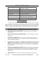
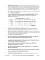
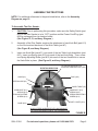
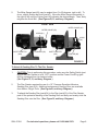
10” DISC SANDER – BENCH TYPE
Model 47404
Set up And Operating Instructions
Diagrams within this manual may not be drawn proportionally.
Due to continuing improvements, actual product may differ slightly from the product described herein.
Distributed Exclusively by Harbor Freight Tools®.
3491 Mission Oaks Blvd., Camarillo, CA 93011
Visit our website at: http://www.harborfreight.com
Read this material before using this product.
Failure to do so can result in serious injury.
Save this manual.
Copyright© 2007 by Harbor Freight Tools®. All rights reserved. No portion of this
manual or any artwork contained herein may be reproduced in any shape or form
without the express written consent of Harbor Freight Tools.
For technical questions or replacement parts, please call 1-800-444-3353.
SPECIFICATIONS TABLE
Electrical Requirements
Sanding Disc Diameter
Sanding Disc Type
Dust Collection Port
Table Dimensions
Table Tilt Angle
Table Tilt Scale Increments
Miter Gauge Scale
Base Mounting Holes
Base Dimensions
120 V / 60 Hz / 3/4 HP / 13.4 Amps
Single Phase / 1,750 RPM
10”
Pressure Sensitive Adhesive (PSA)
1-3/8” O.D.
11-3/8” W x 5-1/2” L
0 to 45 Degrees (Downward)
15 Degrees
0 to 60 Degrees
In 1 Degree Increments – Right and Left
3/8” (Qty: 2)
2 Base Legs at: 2” W x 8-7/8” L
SAVE THIS MANUAL
You will need this manual for the safety warnings and precautions, assembly,
operating, inspection, maintenance and cleaning procedures, parts list and assembly
diagram. Keep your invoice with this manual. Write the invoice number on the inside of the
front cover. Keep this manual and invoice in a safe and dry place for future reference.
GENERAL SAFETY WARNINGS AND PRECAUTIONS
1.
KEEP WORK AREA CLEAN AND DRY. Cluttered, damp, or wet work areas
invite injuries.
2.
KEEP CHILDREN AWAY FROM WORK AREA. Do not allow children to handle
this product.
3.
STORE IDLE EQUIPMENT. When not in use, tools and equipment should be
stored in a dry location to inhibit rust. Always lock up tools and equipment, and
keep out of reach of children.
4.
DO NOT USE THIS PRODUCT IF UNDER THE INFLUENCE OF ALCOHOL OR
DRUGS. Read warning labels on prescriptions to determine if your judgement or
reflexes are impaired while taking drugs. If there is any doubt, do not attempt to
use this product.
5.
USE EYE AND BREATHING PROTECTION. Wear ANSI approved safety impact
eyeglasses and an ANSI approved dust mask when using this product. ANSI
approved safety impact eyeglasses and dust masks are available from Harbor
Freight Tools.
6.
DRESS SAFELY. Do not wear loose clothing or jewelry, as they can become
SKU 47404
For technical questions, please call 1-800-444-3353.
Page caught in moving parts. Wear a protective hair covering to prevent long hair from
becoming caught in moving parts. If wearing a long-sleeve shirt, roll sleeves up
above elbows.
7.
DO NOT OVERREACH. Keep proper footing and balance at all times to prevent
tripping, falling, back injury, etcetera.
8.
INDUSTRIAL APPLICATIONS MUST FOLLOW OSHA REQUIREMENT.
9.
STAY ALERT. Watch what you are doing at all times. Use common sense. Do
not use this product when you are tired or distracted from the job at hand.
10.
CHECK FOR DAMAGED PARTS. Before using this product, carefully check that
it will operate properly and perform its intended function. Check for damaged
parts and any other conditions that may affect the operation of this product.
Replace or repair damaged or worn parts immediately.
11.
REPLACEMENT PARTS AND ACCESSORIES: When servicing, use only
identical replacement parts. Only use accessories intended for use with this
product. Approved accessories are available from Harbor Freight Tools.
12.
MAINTAIN THIS PRODUCT WITH CARE. Keep this product clean, dry, and
keep all cutting bits sharp for better and safer performance.
13.
MAINTENANCE: For your safety, service and maintenance should be performed
regularly by a qualified technician.
14.
USE THE RIGHT TOOL FOR THE JOB. Do not attempt to force a small tool or
attachment to do the work of a larger industrial tool. There are certain
applications for which this tool was designed. It will do the job better and more
safely at the rate for which it was intended. Do not modify this tool, and do not
use this tool for a purpose for which it was not intended.
15.
WARNING: The warnings, precautions, and instructions discussed in this manual
cannot cover all possible conditions and situations that may occur. The operator
must understand that common sense and caution are factors, which cannot be
built into this product, but must be supplied by the operator.
SPECIFIC PRODUCT WARNINGS AND PRECAUTIONS
1.
MAINTAIN A SAFE WORKING ENVIRONMENT. Keep the work area well lit.
Make sure there is adequate surrounding workspace. Always keep the work
area free of obstructions, grease, oil, trash, and other debris. Do not use the
Disc Sander in areas near flammable chemicals, dusts, and vapors. Do not use
the Disc Sander in a damp or wet location.
SKU 47404
For technical questions, please call 1-800-444-3353.
Page 2.
GROUND THIS PRODUCT. The electrical Power Cord/Plug (part #34) for this
product is equipped with a grounded, 3-prong Plug. Never remove the grounding
prong or modify the Plug in any way. Do not use adapter plugs with this product.
To comply with the National Electric Code, and to provide additional protection
from the risk of electrical shock, this product should only be connected to a 120
Volt, 3-hole electrical outlet that is protected by a Ground Fault Circuit Interrupter
(GFCI). (See Assy. Diagram.)
3.
IF AN EXTENSION CORD (not provided) IS USED, MAKE SURE TO USE
ONLY UL APPROVED CORDS HAVING THE CORRECT GAUGE AND
LENGTH. (See Figure A.)
AWG RATING CHART - 120 VOLT
FIGURE A
4.
PROPERLY ALIGN THE WORK TABLE (part #7). Make sure the distance
between the Work Table and Sanding Disc (part #14) does not exceed 1/16”.
5.
REDUCE THE RISK OF ACCIDENTAL STARTING. Make sure the Safety Switch
(part #32) is in the “OFF” position before plugging the Power Cord/Plug (part #34)
into a grounded, 3-hole, 120 Volt, electrical outlet.
(See Figure B, and Assy. Diagram.)
6.
PRIOR TO STARTING THE DISC SANDER, MAKE SURE ALL ADJUSTING
KEYS AND WRENCHES ARE REMOVED FROM THE TOOL.
7.
ALWAYS FEED THE WORKPIECE INTO AND AGAINST THE DIRECTION OF
THE ROTATING SANDING DISC (part #14).
8.
NEVER STAND OR HAVE AN OBSERVER STAND IN LINE WITH THE
SPINNING SANDING DISC (part #14).
9.
USE THE PROPER SIZE AND TYPE OF SANDING DISC (10”, PRESSURE
SENSITIVE ADHESIVE).
10.
HOLD THE WORKPIECE FIRMLY SO THAT IT WILL NOT BE PULLED FROM
YOUR HANDS DURING THE SANDING PROCESS.
11.
FEED THE MATERIAL GRADUALLY. Do not force the machine to remove
SKU 47404
For technical questions, please call 1-800-444-3353.
Page material faster than it was designed to sand.
12.
DO NOT ATTEMPT TO SAND WORKPIECES TOO SMALL TO SAFELY HOLD
BY HAND. Attempting to hold onto a very small workpiece will bring fingers and
hands in dangerous proximity to the spinning sanding disc.
13.
WHEN SANDING A LARGE WORKPIECE, MAKE SURE IT IS PROPERLY
SUPPORTED AT THE WORK TABLE (part #7) HEIGHT.
14.
NEVER LEAVE THE DISC SANDER UNATTENDED WHEN IT IS RUNNING.
Turn off the machine, and wait until it has completely stopped before leaving.
15.
ALWAYS UNPLUG THE DISC SANDER FROM ITS ELECTRICAL SUPPLY
SOURCE BEFORE PERFORMING ANY INSPECTION, MAINTENANCE, OR
CLEANING PROCEDURES.
16.
WARNING: Some dust created by power sanding, sawing, grinding, drilling, and
other construction activities, contain chemicals known (to the State of California)
to cause cancer, birth defects or other reproductive harm. Some examples of
these chemicals are: lead from lead-based paints, crystalline silica from bricks
and cement or other masonry products, arsenic and chromium from chemically
treated lumber. Your risk from these exposures varies, depending on how often
you do this type of work. To reduce your exposure to these chemicals: work in
a well ventilated area, and work with approved safety equipment, such as those
dust masks that are specially designed to filter out microscopic particles.
(California Health & Safety Code 25249.5, et seq.)
18.
WARNING: People with pacemakers should consult their physician(s) before
using this product. Operation of electrical equipment in close proximity to a heart
pacemaker could cause interference or failure of the pacemaker.
UNPACKING
When unpacking, check to make sure all the parts shown on the Parts List on page 11
are included. If any parts are missing or broken, please call Harbor Freight Tools at the
number shown on the cover of this manual as soon as possible.
SKU 47404
For technical questions, please call 1-800-444-3353.
Page ASSEMBLY INSTRUCTIONS
NOTE: For additional references to the parts listed below, refer to the Assembly
Diagram on page 12.
To Assemble The Disc Sander:
1.
CAUTION: Prior to performing this procedure, make sure the Safety Switch (part
#32) of the Disc Sander is in its “OFF” position and the Power Cord/Plug (part
#34) is unplugged from its electrical outlet.
(See Figures C, D, and Assy. Diagram.)
2.
Assembly of the Disc Sander requires the attachment of one Knob Bolt (part #11)
on the front end and back end of the Work Table (part #7).
(See Figure B, and Assy. Diagram.)
3.
Insert one Knob Bolt (part #11) onto each of the two Table Lock Assemblies (part
#10). Insert one Spring (part #12) into each of the two Knob Bolts. Then, screw
one Spring Adjusting Screw (part #13) into each of the two Knob Bolts to secure
the Knob Bolts in place. (See Figure B, and Assy. Diagram.)
ROTATION DIRECTION
10” PRESSURE SENSITIVE
ADHESIVE SANDING DISC (#14)
KNOB (#1)
DISC (#15)
MITER GAUGE (#3)
WORKPIECE
KNOB BOLT (#11)
SPRING (#12)
SPRING ADJUSTING
SCREW (#13)
BASE (#23)
WORK TABLE (#7)
KNOB BOLT (#11)
SPRING (#12)
SPRING ADJUSTING
SCREW (#13)
DUST COVER (#18)
ALWAYS FEED WORKPIECE INTO AND AGAINST
THE ROTATION DIRECTION OF THE SANDING DISC.
FIGURE B
SKU 47404
For technical questions, please call 1-800-444-3353.
Page MACHINE ADJUSTMENT INSTRUCTIONS
NOTE: For additional references to the parts listed below, refer to the Assembly
Diagram on page 12.
To Adjust The Table Angle:
1.
CAUTION: Prior to performing this procedure, make sure the Safety Switch (part
#32) of the Disc Sander is in its “OFF” position and the Power Cord/Plug (part
#34) is unplugged from its electrical outlet.
(See Figures C, D, and Assy. Diagram.)
2.
The Work Table (part #7) may be angled downward from 0 to 45 degrees. To
do so, slightly loosen the two Knob Bolts (part #11). Move the Work Table
downward until the Angle Scale indicates the desired angle. Then, firmly
retighten the two Knob Bolts. (See Figures B, C, and Assy. Diagram.)
FRONT VIEW
SAFETY SWITCH (#32)
SAFETY SWITCH (#32)
DISC (#15)
WORK TABLE (#7)
DISC (#15)
ANGLE SCALE
KNOB BOLT (#11)
KNOB BOLT (#11)
ANGLE SCALE
WORK TABLE (#7)
FIGURE C
To Adjust
1.
The Miter Angle:
CAUTION: Prior to performing this procedure, make sure the Safety Switch (part
#32) of the Disc Sander is in its “OFF” position and the Power Cord/Plug (part
#34) is unplugged from its electrical outlet.
(See Figures C, D, and Assy. Diagram.)
SKU 47404
For technical questions, please call 1-800-444-3353.
Page 2.
The Miter Gauge (part #3) may be angled from 0 to 60 degrees, right or left. To
do so, slightly loosen the Knob (part #1). Move the Miter Gauge horizontally to
the right or left until the Pointer (part #5) indicates the desired angle. Then, firmly
retighten the Knob Bolt. (See Figures B, D, and Assy. Diagram.)
FRONT VIEW
MITER GAUGE (#3)
MITER GAUGE (#3)
KNOB (#1)
KNOB
(#1)
SAFETY SWITCH
(#32)
POINTER (#5)
SAFETY SWITCH
(#32)
POINTER (#5)
FIGURE D
To Attach A Sanding Disc To The Disc Sander:
1.
CAUTION: Prior to performing this procedure, make sure the Safety Switch (part
#32) of the Disc Sander is in its “OFF” position and the Power Cord/Plug (part
#34) is unplugged from its electrical outlet.
(See Figures C, D, and Assy. Diagram.)
2.
The Disc Sander requires the use of a 10”, Pressure Sensitive Adhesive,
Sanding Disc (part #14). Additional replacement Sanding Discs are available
from Harbor Freight Tools. (See Figure B, and Assy. Diagram.)
3.
To attach the Sanding Disc (part #14) to the Disc (part #15) of the Disc Sander,
peel off the protective backing of the Sanding Disc and firmly and evenly stick the
Sanding Disc onto the Disc. (See Figure B, and Assy. Diagram.)
SKU 47404
For technical questions, please call 1-800-444-3353.
Page OPERATING INSTRUCTIONS
NOTE: For additional references to the parts listed below, refer to the Assembly
Diagram on page 12.
1.
CAUTION: Prior to beginning to use, make sure the Safety Switch (part #32) is
in its “OFF” position and the Power Cord/Plug (part #34) is unplugged from its
electrical outlet. (See Figures C, D, and Assy. Diagram.)
2.
Make all necessary adjustments to the Disc Sander as previously discussed.
Make sure the distance between the Work Table (part #7) and Sanding Disc and
Sanding Disc (part #14) does not exceed 1/16”.
3.
Plug the Power Cord/Plug (part #34) into the nearest 120 volt, grounded, 3prong, electrical outlet. (See Figure B, and Assy. Diagram.)
4.
Turn the Safety Switch (part #32) to its “ON” position, and allow sufficient time
for the Sanding Disc (part #14) to spin at full speed for 2 to 3 minutes. Check for
proper sanding disc alignment. (See Figure B, and Assy. Diagram.)
5.
With both hands, slowly and carefully place the workpiece on the Work Table
(part #7) and against the flat edge of the Miter Gauge (part #3), taking care not to
allow the workpiece to immediately touch the spinning Sanding Disc (part #14).
(See Figure B, and Assy. Diagram.)
6.
With both hands, firmly hold the workpiece down on the Work Table (part #7) and
against the Miter Gauge (part #3). While holding the workpiece with one hand,
use the other hand to grasp the Miter Gauge and slowly push the workpiece into
the spinning Sanding Disc. CAUTION: ALWAYS KEEP HANDS AND FINGERS
AWAY FROM THE SANDING DISC. (See Figures B, D, and Assy. Diagram.)
7.
NOTE: Make sure to feed the workpiece gradually into the spinning Sanding
Disc. Do not force the machine to remove material faster than it was designed
to sand. If necessary, use the Miter Gauge (part #3) to back the workpiece away
from the spinning Sanding Disc (part #14) and repeat Step #6 until the desired
amount of material has been sanded off the workpiece.
(See Figures B, D, and Assy. Diagram.)
8.
Once the sanding job is completed, back the workpiece slightly away from the
spinning Sanding Disc (part #14). Keep a firm grip on the workpiece with one
hand, and with the other hand turn the Safety Switch (part #32) to its “OFF”
position. Wait until the Sanding Disc has completely stopped spinning. Then,
remove the workpiece from the machine and unplug the Power Cord/Plug (part
#34) from its electrical outlet. (See Figures B, C, D, and Assy. Diagram.)
SKU 47404
For technical questions, please call 1-800-444-3353.
Page INSPECTION, MAINTENANCE, AND CLEANING
NOTE: For additional references to the parts listed below, refer to the Assembly
Diagram on page 12.
1.
CAUTION: Always turn the Safety Switch (part #32) to its “OFF” position, unplug
the Power Cord/Plug (part #34) from its electrical outlet, and wait until the
Sanding Disc (part #14) has completely stopped spinning before performing any
inspection, maintenance, or cleaning.
2.
BEFORE EACH USE, inspect the general condition of the Disc Sander. Check
for loose screws, misalignment or binding of moving parts, cracked or broken
parts, damaged electrical wiring, and any other condition that may affect its safe
operation. If abnormal noise or vibration occurs, have the problem corrected
before further use. Do not use damaged equipment.
3.
DAILY: Sanding Discs (part #14) must be sharp and clean to perform properly.
Depending on materials sanded and frequency of machine use, Sanding Discs
become clogged with wood, metal particles, and become dull. Dull Sanding
Discs rub the workpiece rather than cut, which results in increased friction, higher
temperatures, and a burned workpiece. As often as possible, check the condition
of the Sanding Disc and, if necessary, replace a worn Sanding Disc with a new,
10” Pressure Sensitive Adhesive disc. (See “To Attach A Sanding Disc To The
Disc Sander” section in this manual for further information.)
4.
DAILY: With a soft brush, cloth, or vacuum, remove all debris from the Disc
Sander. Then, use a premium quality, lightweight machine oil to lubricate all
moving parts.
PLEASE READ THE FOLLOWING CAREFULLY
THE MANUFACTURER AND/OR DISTRIBUTOR HAS PROVIDED THE PARTS LIST AND ASSEMBLY
DIAGRAM IN THIS MANUAL AS A REFERENCE TOOL ONLY. NEITHER THE MANUFACTURER OR
DISTRIBUTOR MAKES ANY REPRESENTATION OR WARRANTY OF ANY KIND TO THE BUYER THAT
HE OR SHE IS QUALIFIED TO MAKE ANY REPAIRS TO THE PRODUCT, OR THAT HE OR SHE IS
QUALIFIED TO REPLACE ANY PARTS OF THE PRODUCT. IN FACT, THE MANUFACTURER AND/OR
DISTRIBUTOR EXPRESSLY STATES THAT ALL REPAIRS AND PARTS REPLACEMENTS SHOULD BE
UNDERTAKEN BY CERTIFIED AND LICENSED TECHNICIANS, AND NOT BY THE BUYER. THE BUYER
ASSUMES ALL RISK AND LIABILITY ARISING OUT OF HIS OR HER REPAIRS TO THE ORIGINAL
PRODUCT OR REPLACEMENT PARTS THERETO, OR ARISING OUT OF HIS OR HER INSTALLATION
OF REPLACEMENT PARTS THERETO.
SKU 47404
For technical questions, please call 1-800-444-3353.
Page 10
PARTS LIST
Part
1
2
3
4
5
6
7
8
9
10
11
12
13
14
15
16
17
18
19
20
21
22
23
24
25
26
27
Description
Knob
Screw (M5 x 6)
Miter Gauge
Washer
Pointer
Gauge Sliding Bar
Work Table
Round Body Threaded Rod
Washer
Table Lock Assembly
Knob Bolt
Spring
Spring Adjusting Screw
Sanding Disc
Disc
Washer
Screw (M6 x 12)
Dust Cover
Screw (M5 x 8)
Spring Washer
Big Pointer
Screw (M5 x 16)
Base
Screw (M5 x 12)
Rubber Pad
Screw (M5 x 20)
Motor Housing
Qty.
1
1
1
19
1
1
1
2
2
2
2
2
2
1
1
1
1
1
7
7
1
4
1
4
4
1
1
Part
28*
29*
30*
31*
32*
33*
34*
35*
36*
37**
38**
39**
40**
41**
42**
43**
44**
45**
46**
47**
48**
49**
50**
51**
52**
53*
54**
Description
Rubber Ring
Terminal Box
Screw (ST3.5 x 14)
Switch Plate
Safety Switch
Swivel Clamp
Cord/Plug
Capacitor Clip
Capacitor (6uF/8uF)
Wavy Washer
Stator
Bearing (6004)
Key (C5 x 12)
Rotor
Screw (M4 x 35)
Bearing (6203)
Washer
Nut (M4)
End Bell
Plastic Washer
Nut (M5)
Fan
Fan Cover
Spring Washer
Screw (M4 x 16)
Switch Assembly
Motor Assembly
Qty.
1
1
4
1
1
1
1
1
1
1
1
1
1
1
1
1
4
1
1
3
4
1
1
3
3
1
1
* Available only as a complete Switch Assembly (see Part #53).
** Available only as a complete Motor Assembly (see Part #54).
SKU 47404
For technical questions, please call 1-800-444-3353.
Page 11
NOTE: Some parts are listed and shown for illustration purposes only, and are not
available individually as replacement parts.
SKU 47404
For technical questions, please call 1-800-444-3353.
Page 12
LIMITED 90 DAY WARRANTY
Harbor Freight Tools Co. makes every effort to assure that its products meet high
quality and durability standards, and warrants to the original purchaser that this product
is free from defects in materials and workmanship for the period of 90 days from the date
of purchase. This warranty does not apply to damage due directly or indirectly, to misuse,
abuse, negligence or accidents, repairs or alterations outside our facilities, criminal activity,
improper installation, normal wear and tear, or to lack of maintenance. We shall in no event
be liable for death, injuries to persons or property, or for incidental, contingent, special
or consequential damages arising from the use of our product. Some states do not allow
the exclusion or limitation of incidental or consequential damages, so the above limitation
of exclusion may not apply to you. This warranty is expressly in lieu of all
other warranties, express or implied, including the warranties of
merchantability and fitness.
To take advantage of this warranty, the product or part must be returned to us with
transportation charges prepaid. Proof of purchase date and an explanation of the complaint
must accompany the merchandise. If our inspection verifies the defect, we will either
repair or replace the product at our election or we may elect to refund the purchase price
if we cannot readily and quickly provide you with a replacement. We will return repaired
products at our expense, but if we determine there is no defect, or that the defect resulted
from causes not within the scope of our warranty, then you must bear the cost of returning
the product.
This warranty gives you specific legal rights and you may also have other rights
which vary from state to state.
3491 Mission Oaks Blvd. • PO Box 6009 • Camarillo, CA 93011 • (800) 444-3353
REV 07j
SKU 47404
For technical questions, please call 1-800-444-3353.
Page 13