1
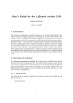
7” POLISHER/SANDER
Model 46507
ASSEMBLY AND
OPERATING INFORMATION
®
3491 Mission Oaks Blvd., Camarillo, CA 93011
Visit our Web site at http://www.harborfreight.com
Copyright
2001 by Harbor Freight Tools®. All rights reserved. No portion of this
manual or any artwork contained herein may be reproduced in any shape or form
without the express written consent of Harbor Freight Tools.
For technical questions please call 1-800-444-3353
SPECIFICATIONS TABLE
Item
Electrical
Requirements
Spindle Thread
Handle Mounting
Wool Cover Size
Tool Length
Tool Weight
Description
120V / 60 Hz / 11 Load Amp
Double Insulated Motor
1,000 - 3,000 RPM Variable Speed
16 Gauge Power Cord
5/8”-11 Threads Per Inch
Threaded, 3 Positions
8”
17”
8.40 Lbs. With Wool Cover
96GA
E210256
SAVE THIS MANUAL
You will need this manual for the safety warnings and precautions, assembly,
operating, inspection, maintenance, and cleaning procedures, parts list and
assembly diagram. Keep your invoice with this manual. Write the invoice
number on the inside of the front cover. Keep this manual and invoice in a safe
and dry place for future reference.
GENERAL SAFETY WARNINGS AND PRECAUTIONS
1.
KEEP WORK AREA CLEAN AND DRY. Cluttered, damp or wet work areas
invite injuries.
2.
KEEP CHILDREN AWAY FROM WORK AREA. Do not allow children to handle
this product.
3.
STORE IDLE EQUIPMENT. When not in use, tools and equipment should be
stored in a dry location to inhibit rust. Always lock up tools and equipment and
keep out of reach of children.
4.
DO NOT USE THIS PRODUCT IF UNDER THE INFLUENCE OF ALCOHOL OR
DRUGS. Read warning labels on prescriptions to determine if your judgment or
reflexes are impaired while taking drugs. If there is any doubt, do not attempt to
use this product.
5.
USE EYE, BREATHING, AND HEARING PROTECTION. Wear ANSI approved
safety impact eye glasses, ANSI approved breathing protection, and ANSI
approved hearing protection when using this product. ANSI approved safety
impact eye glasses, dust masks, and hearing protectors are available from
Harbor Freight Tools.
SKU 46507
PAGE 2
Rev 12/01
6.
DRESS SAFELY. Non-skid footwear or safety shoes should be used when
working with this product. Do not wear loose clothing or jewelry as they can
become caught in moving parts. Wear a protective hair covering to prevent long
hair from becoming caught in moving parts. If wearing a long-sleeve shirt, roll
sleeves up above elbows.
7.
INDUSTRIAL APPLICATIONS MUST FOLLOW OSHA REQUIREMENTS.
8.
DO NOT OVERREACH. Keep proper footing and balance at all times to prevent
tripping, falling, back injury, etcetera.
9.
STAY ALERT. Watch what you are doing at all times. Use common sense. Do
not use this product when you are tired or distracted from the job at hand.
10.
CHECK FOR DAMAGED PARTS. Before using this product, carefully check that
it will operate properly and perform its intended function. Check for damaged
parts and any other conditions that may affect the operation of this product.
Replace or repair damaged or worn parts immediately.
11.
REPLACEMENT PARTS AND ACCESSORIES. When servicing, use only
identical replacement parts. Only use accessories intended for use with this
product. Approved accessories are available from Harbor Freight Tools.
12.
MAINTAIN THIS PRODUCT WITH CARE. Keep this tool clean and dry for better
and safer performance.
13.
MAINTENANCE: For your safety, service and maintenance should be performed
regularly by a qualified technician.
14.
USE THE RIGHT PRODUCT FOR THE RIGHT JOB. There are certain
applications for which this product was designed. Do not use small equipment,
tools or attachments to do the work of larger industrial equipment, tools or
attachments. Do not use this product for a purpose for which it was not intended.
SPECIFIC PRODUCT WARNINGS AND PRECAUTIONS
1.
MAKE SURE THE POWER SWITCH (part #33) IS IN THE “OFF” POSITION
BEFORE PLUGGING IN THE POWER CORD (part #36).
2.
DO NOT ABUSE THE POWER CORD. Do not use the Power Cord (part #36) to
pull the Plug from a power outlet. Keep Power Cord away from heat, oil, sharp
edges, and moving parts. Replace a damaged Power Cord immediately. Route
the Power Cord safely. Protect it from being damaged by other equipment in the
work area. Do not route the Power Cord where it can be walked on or tripped
over.
SKU 46507
PAGE 3
3.
IF YOU USE AN EXTENSION CORD, MAKE SURE TO USE ONLY UL
APPROVED CORDS HAVING THE CORRECT GAUGE AND LENGTH.
(SEE FIGURE A.)
REQUIRED EXTENSION CORD GAUGE
Namep late
Amp eres
0-5
5.1 - 8
8.1 - 12
12.1 - 15
15.1 - 20
25’
16
16
14
12
10
Extension C ord Length
50’
75’
100’
150’
16
16
14
12
16
14
12
10
14
12
10
12
10
10
10
10
-
200’
12
-
FIGURE A
4.
MAINTAIN A SAFE WORK ENVIRONMENT. Do not use this tool in or near
damp or wet areas. Do not expose this product to rain. Keep work area well lit.
Make sure there is adequate surrounding work space. Use this tool in a well
ventilated area. Do not operate this tool in the presence of flammable liquids,
gases, or dust. To avoid accidental electric shock, do not let your body come in
contact with grounded surfaces such as pipes, radiators, ranges and
refrigerators.
5.
DO NOT FORCE THE EQUIPMENT. This Polisher/Sander will do the work better
and safer at the speed and capacity for which it was designed.
6.
REMOVE ALL ADJUSTING WRENCHES FROM THE POLISHER/SANDER
BEFORE TURNING IT ON.
7.
AVOID UNINTENTIONAL STARTING. Make sure you are prepared to begin
work before turning the Power Switch (part #33) “ON”.
8.
ALLOW THE POLISHING DISC (part #44) AND WOOL COVER (part #45), AS
WELL AS THE RUBBER BACKING PLATE (#46) WHEN SANDING, TO SPIN
UP TO FULL SPEED BEFORE PRESSING THEM ONTO THE WORKPIECE.
When turning off the Polisher/Sander, allow the Rubber Backing Plate or Polishing Disc to spin down and stop on their own. Do not press against to stop them.
9.
DO NOT FORCE THE POLISHING DISC (part #44) AND WOOL COVER (part
#45), RUBBER BACKING PLATE (#46) WITH SANDPAPER DISC ONTO THE
WORKPIECE WHEN USING. Apply moderate pressure, allowing the Polisher/
Sander to do the work without being forced.
10.
MAKE SURE THE WORKPIECE IS FREE FROM BURRS AND ANY OTHER
FOREIGN OBJECTS WHICH COULD DAMAGE THE POLISHER/SANDER.
SKU 46507
PAGE 4
11.
MAKE SURE THE WORKPIECE IS SUPPORTED AT ALL TIMES DURING
OPERATION. Use a Roller Stand (not provided) with larger workpieces if
necessary.
12.
MAINTAIN CONTROL OF THE WORKPIECE AT ALL TIMES. Whenever
possible, secure the workpiece with clamps, in a vise, etcetera.
13.
ALWAYS DISCONNECT THE POLISHER/SANDER FROM ITS ELECTRICAL
SUPPLY SOURCE WHEN NOT IN USE. Make sure to unplug the Polisher/
Sander when leaving the work area, moving the tool from one location to another, handing the Polisher/Sander to another person, changing the Polishing/
Rubber Backing Plate disc.
14.
THIS TOOL IS INTENDED TO BE USED ONLY AS A POLISHER AND AS A
SANDER. DO NOT ATTEMPT TO USE THIS TOOL AS AN ANGLE GRINDER
OR IN ANY OTHER WAY THAN ITS INTENDED PURPOSE. NEVER INSTALL
A CARBIDE TIPPED OR STEEL CIRCULAR SAW BLADE FOR USE IN THIS
POLISHER/SANDER. NEVER INSTALL A WOOD CARVING BLADE, CARVING DISC WITH CHAIN SAW CUTTERS, OR A CUTTING CARVING DISC ON
THIS POLISHER/SANDER.
15.
WARNING: Some dust created by power sanding, sawing, grinding, drilling, and
other construction activities, contain chemicals known (to the State of California)
to cause cancer, birth defects or other reproductive harm. Some examples of
these chemicals are: lead from lead-based paints, crystalline silica from bricks
and cement or other masonry products, arsenic and chromium from chemically
treated lumber. Your risk from these exposures varies, depending on how often
you do this type of work. To reduce your exposure to these chemicals: work in a
well ventilated area, and work with approved safety equipment, such as those
dust masks that are specially designed to filter out microscopic particles.
(California Health & Safety Code 25249.5 et seq.)
16.
WARNING: People with pacemakers should consult with their physician(s)
before using this product. Operation of equipment in close proximity to a heart
pacemaker could cause interference or failure of the pacemaker.
UNPACKING
When unpacking, check to make sure all parts shown on the Parts List (page 11) are
included. If any parts are missing or broken, please call Harbor Freight Tools at the
number shown on the cover of this manual as soon as possible.
SKU 46507
PAGE 5
ASSEMBLY INSTRUCTIONS
IMPORTANT
Carefully inspect the condition of the accessory before use and check the accessory
continually during use. If any damage is noted, stop immediately and replace the
accessory with an undamaged one. Harbor Freight Tools cannot be held responsible
for damage caused by using a damaged accessory on this tool.
NOTE: For additional references to the parts listed below, refer to the Assembly
Diagram on page 11 of this manual.
To Attach The Polishing Disc And Wool Cover:
1.
Caution: Prior to installing the Wool Compounding Bonnet (part #44), make sure
the Polisher/Sander is disconnected from its electrical power source.
2.
Place the Adaptor (part #1) on the Spindle (part #3) of the Polisher/Sander, and
place the Wool Compounding Bonnet (part #44) on the Adaptor (See Figure B,
and Assy. Diagram.)
3.
Depress the Brake Pin (part #18) to keep the Spindle (part #3) from turning, and
hand screw the Adaptor (part #1) onto the Spindle. (See Figures B, C, and Assy.
Diagram.)
4.
Then, use the Spanner (part #43) provided to keep the Adaptor (part #1) from
turning, and firmly hand tighten the Wool Compounding Bonnet onto the Adaptor.
(See Figures B, C, and Assy. Diagram.)
ADAPTOR (#1)
SPINDLE (#3)
BRAKE PIN (#18)
BRUSH CAP (#40)
CARBON BRUSH (#41)
BRUSH HOLDER (#42)
(Qty. 2 EACH)
WOOLCOMPOUNDING BONNET (#44)
VARIABLE SWITCH (#31)
SWITCH (#33)
SWITCH LOCK
BACK HANDLE (#39)
FIGURE B
SKU 46507
PAGE 6
REV 09/02
REV 06/05
To Attach The Side Handle:
1.
NOTE: The Side Handle (part #20) may be attached either on the right, left, or
top side of the Polisher/Sander. (See Figure C, and Assy. Diagram.)
2.
To attach the Side Handle (part #20), remove the Rubber Plunge (part #19) from
either the right, left, or top side of the Polisher/Sander in order to expose the
threaded mounting hole. (See Figure C, and Assy. Diagram.)
3.
Firmly hand tighten the threaded portion of the Side Handle (part #20) into the
desired mounting hole of the Polisher/Sander. (See Figure C, and Assy. Diagram.)
BRAKE PIN (#18)
MOUNTING
HOLE
MOUNTING HOLE
SIDE HANDLE (#20)
MOUNTING HOLE
WOOL COVER (#45)
BRUSH CAP (#40)
CARBON BRUSH (#41)
BRUSH HOLDER (#42)
BRUSH CAP (#40)
CARBON BRUSH (#41)
BRUSH HOLDER (#42)
SWITCH
LOCK
VARIABLE SWITCH (#31)
BACK HANDLE (#39)
POWER CORD (#36)
FIGURE C
OPERATING INSTRUCTIONS
NOTE: For additional references to the parts listed below, refer to the Assembly
Diagram on page 12 of this manual.
SKU 46507
PAGE 8
To Attach The Rubber Backing Plate And Sandpaper:
1.
Caution: Prior to installing the Rubber Backing Plate (part #46), make sure the
Polisher/Sander is disconnected from its electrical power source.
2.
Rest the tool on a flat surface. Depress the Brake Pin (#18) to keep the Spindle
(#3) from turning.
3.
Screw the Rubber Backing Plate (46) onto the threaded end of the Spindle (#3)
until it is snug. (See diagram below)
4.
Ahere Sandpaper Disc (not included) evenly across the Rubber Backing Plate.
The Rubber Backing Plate has a self-sticking backing, so be sure only to use
Sandpaper Discs with a self-sticking material. Press Sandpaper Disc firmly onto
pad. When finished, release pressure on the Brake Pin (#18).
5.
When finished sanding, peel the Sandpaper Disc away from the Plate.
RUBBER BACKING PLATE (#46)
SANDPAPER DISC
SPINDLE (#3)
BRAKE PIN (#18)
SKU 46507
PAGE 7
1.
Caution: Check to make sure the Switch (part #33) is in its “OFF” position before
plugging the Power Cord (part #36) into a 110-120 Volt, grounded,
electrical power outlet. (See Figures B, C, and Assy. Diagram.)
2.
Make sure to use both hands to firmly grip the Polisher/Sander by its Side
Handle (part #20) and Back Handle (part #39). (See Figures B, C, and Assy.
Diagram.)
3.
To turn on the Polisher/Sander, squeeze the Switch (part #33). To turn off the
Polisher/Sander, release pressure on the Switch. NOTE: For automatic, continuous running, squeeze the Switch while, at the same time, depressing the Switch
Lock. This locks the Switch in its “ON” position. To turn off the Polisher/Sander,
squeeze and quickly release pressure on the Switch. This unlocks the Switch,
and allows the Polisher/Sander to automatically turn off. (See Figures B, C, and
Assy. Diagram.)
4.
Allow the Polisher/Sander to spin up to full speed before pressing it onto the
workpiece. (See Figures B, C, and Assy. Diagram.)
5.
NOTE: The Polisher/Sander can be operated at different speeds (from 1,000
RPM to up to 3,000 RPM), depending on the material of the workpiece. To
change speeds, make sure the Polisher/Sander is off. Then, select the desired
speed, using the Variable Switch (part #31). (See Figures B, C, and Assy.
Diagram.)
6.
Do not force the Polisher/Sander onto the workpiece. Apply moderate pressure,
allowing the Polisher/Sander to do the work without being forced. (See Figures
B, C, and Assy. Diagram.)
7.
Move the Polisher/Sander along the workpiece in small, circular, patterns. (See
Figures B, C, and Assy. Diagram.)
8.
When finished, turn off the Polisher/Sander and allow the Polishing Disc or the
Rubber Backing Plate to spin down and stop on their own. Do not press against
the disc to stop them. (See Figures B, C, and Assy. Diagram.)
INSPECTION, MAINTENANCE, AND CLEANING
1.
Caution: Always disconnect the Polisher/Sander from its electrical power supply
source before performing any inspection, maintenance, or cleaning.
2.
Before each use, inspect the general condition of the Polisher/Sander. Inspect
switch, power plug and cord assembly, and extension cord (if used) for damage.
Check for loose screws, misalignment, binding of moving parts, broken, cracked,
or improper mounting of the Polishing Disc or the Rubber Backing Plate, broken
SKU 46507
PAGE 9
parts and any other condition that may affect its safe operation. If abnormal
noise or vibration occurs, turn off the Polisher/Sander immediately and have the
problem corrected before further use. Do not use damaged equipment.
3.
The Polisher/Sander features two Carbon Brushes (part #41) which, periodically,
should be examined for wear. The Carbon Brushes are located on each side of
the Plastic Housing (part #29). To inspect or replace the Carbon Brushes, use a
small standard screwdriver to remove the Brush Cap (part #40). Examine the
concave surface of the Carbon Brushes. The surface should be smooth and
clean. If there are large scratch marks in the Brushes, or parts of the Brushes
have broken off, replace both Brushes immediately with approved replacement
Brushes from Harbor Freight Tools. To reinstall the Brushes, insert them into the
two Brush Holders (part #42). Turn the Brushes vertically so they will fit into the
Brush Holders. Then, replace the Brush Caps. (See Figures B, C, and Assy.
Diagram.)
4.
Do not use solvents to wipe off the Polisher/Sander, as damage may result. If
necessary, wipe with a damp cloth. You may use a mild detergent.
5.
Do not introduce water, dirt, or dust into the electric motor through the motor
vents.
6.
Once clean, lubricate all moving parts with a light oil.
7.
When storing, keep the Polisher/Sander covered with a cloth cover.
PLEASE READ THE FOLLOWING CAREFULLY
THE MANUFACTURER AND/OR DISTRIBUTOR HAS PROVIDED THE PARTS DIAGRAM IN THIS
MANUAL AS A REFERENCE TOOL ONLY. NEITHER THE MANUFACTURER NOR DISTRIBUTOR
MAKES ANY REPRESENTATION OR WARRANTY OF ANY KIND TO THE BUYER THAT HE OR
SHE IS QUALIFIED TO MAKE ANY REPAIRS TO THE PRODUCT OR THAT HE OR SHE IS QUALIFIED TO REPLACE ANY PARTS OF THE PRODUCT. IN FACT, THE MANUFACTURER AND/OR
DISTRIBUTOR EXPRESSLY STATES THAT ALL REPAIRS AND PARTS REPLACEMENTS SHOULD
BE UNDERTAKEN BY CERTIFIED AND LICENSED TECHNICIANS AND NOT BY THE BUYER. THE
BUYER ASSUMES ALL RISK AND LIABILITY ARISING OUT OF HIS OR HER REPAIRS TO THE
ORIGINAL PRODUCT OR REPLACEMENT PARTS THERETO, OR ARISING OUT OF HIS OR HER
INSTALLATION OF REPLACEMENT PARTS THERETO.
SKU 46507
PAGE 10
PARTS LIST
Adaptor
Wool Compounding
Bonnet
Rubber Backing Plate
1
SKU 46507
PAGE 11
REV 09/02
PARTS LIST
43
44
For Polishing
45
Note: #45 includes
Arbor Nut 5/8” - 11 TPI.
For Sanding
NOTE: Some parts are listed and shown for illustration purposes only, and are not
available individually as replacement parts.
SKU 46507
PAGE 12
REV 09/02