1
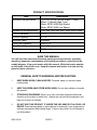
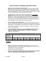
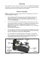
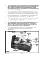
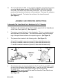
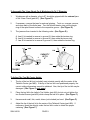
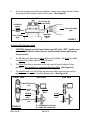
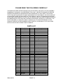
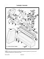
MINI BENCH LATHE Model 04019 ASSEMBLY AND OPERATING INSTRUCTIONS ® 3491 Mission Oaks Blvd., Camarillo, CA 93011 Visit our Web site at: http://www.harborfreight.com Copyright C 2003 by Harbor Freight Tools®. All rights reserved. No portion of this manual or any artwork contained herein may be reproduced in any shape or form without the express written consent of Harbor Freight Tools. For technical questions, please call 1-800-444-3353. PRODUCT SPECIFICATIONS !"#$%&'()* +!-%&"# +!/5()"# "# +#6 7&8: 7&87< =>) @+7< @+"< %& /''/''''-'- ; -; ?## J@; L87&% -+# SAVE THIS MANUAL You will need this manual for the safety warnings and precautions, assembly, operating, inspection, maintenance and cleaning procedures, parts list and assembly diagram. Keep your invoice with this manual. Write the invoice number on the inside of the front cover. Keep this manual and invoice in a safe and dry place for future reference. GENERAL SAFETY WARNINGS AND PRECAUTIONS 1. KEEP WORK AREA CLEAN AND DRY. Cluttered, damp, or wet work areas invite injuries. 2. KEEP CHILDREN AWAY FROM WORK AREA. Do not allow children to handle this product. 3. STORE IDLE EQUIPMENT. When not in use, tools and equipment should be stored in a dry location to inhibit rust. Always lock up tools and equipment, and keep out of reach of children. 4. DO NOT USE THIS PRODUCT IF UNDER THE INFLUENCE OF ALCOHOL OR DRUGS. Read warning labels on prescriptions to determine if your judgement or reflexes are impaired while taking drugs. If there is any doubt, do not attempt to use this product. SKU 04019 PAGE 2 5. USE EYE AND BREATHING PROTECTION. Wear ANSI approved safety impact eye goffles and a full face shield when using this product. In work situations where excessive dust is produced, use an ANSI approved dust mask or respirator. ANSI approved safety impact eye goggles, full face shield, dust mask, and respirator are available from Harbor Freight Tools. 6. DRESS SAFELY. Do not wear loose clothing, jewelry, or gloves as they can become caught in moving parts. Wear a protective hair covering to prevent long hair from becoming caught in moving parts. If wearing a long-sleeve shirt, roll sleeves up above elbows. 7. DO NOT OVERREACH. Keep proper footing and balance at all times to prevent tripping, falling, back injury, etcetera. 8. INDUSTRIAL APPLICATIONS MUST FOLLOW OSHA REQUIREMENTS. 9. STAY ALERT. Watch what you are doing at all times. Use common sense. Do not use this product when you are tired or distracted from the job at hand. 10. CHECK FOR DAMAGED PARTS. Before using this product, carefully check that it will operate properly and perform its intended function. Check for damaged parts and any other conditions that may affect the operation of this product. Replace or repair damaged or worn parts immediately. 11. REPLACEMENT PARTS AND ACCESSORIES: When servicing, use only identical replacement parts. Only use accessories intended for use with this product. Approved accessories are available from Harbor Freight Tools. 12. MAINTAIN THIS PRODUCT WITH CARE. Keep this product clean and dry for better and safer performance. 13. MAINTENANCE: For your safety, service and maintenance should be performed regularly by a qualified technician. 14. USE THE RIGHT TOOL FOR THE JOB. Do not attempt to force a small tool or attachment to do the work of a larger industrial tool. There are certain applications for which this tool was designed. It will do the job better and more safely at the rate for which it was intended. Do not modify this tool, and do not use this tool for a purpose for which it was not intended. 15. WARNING: The warnings, precautions, and instructions discussed in this manual cannot cover all possible conditions and situations that may occur. The operator must understand that common sense and caution are factors, which cannot be built into this product, but must be supplied by the operator. SKU 04019 PAGE 3 SPECIFIC PRODUCT WARNINGS AND PRECAUTIONS 1. MAINTAIN A SAFE WORKING ENVIRONMENT. Keep the work area well lit. Make sure there is adequate surrounding workspace. Always keep the work area free of obstructions, sawdust, grease, oil, trash, and other debris. Do not use the Mini Bench Lathe in areas near flammable chemicals, dusts, and vapors. Do not use the Mini Bench Lathe in a damp or wet location. 2. THE MINI BENCH LATHE IS FACTORY PRE-WIRED FOR 120 VOLT AC USAGE. The Power Cord for this product is equipped with a 120 Volt AC, 2-Prong Plug. Never modify the Plug in any way. To comply with the National Electric Code, and to provide additional protection from the risk of electrical shock, this product should only be connected to a 120 Volt AC, electrical outlet that is protected by a Ground Fault Circuit Interrupter (GFCI). 3. DO NOT ABUSE THE POWER CORD. Do not use the Power Cord to pull its Plug from an electrical power outlet. Keep the Power Cord away from heat, oil, sharp edges, and moving parts. Route the Power Cord safely. Do not route the Power Cord where it can be walked on or tripped over. Replace a damaged Power Cord immediately. 4. IF AN EXTENSION CORD (not included) IS USED, MAKE SURE TO USE ONLY UL APPROVED CORDS HAVING THE CORRECT GAUGE AND LENGTH . (See Figure A.) ! ! "#$%%&'* 67 =7> >=7;A FIGURE ;=7 =7;6 + 67; # < < ? ; 6 ;76 # < < ? ; 6 6766 # < ? ; 6 6 666 # ; 6 7 7 7 6;66 # ; 7 7 7 7 5. REDUCE THE RISK OF ACCIDENTAL STARTING. Make sure the Power Switch (part #2) is in the “OFF” position before plugging the Power Cord into a grounded, 120 Volt AC, electrical outlet. (See Figure B, and Assy. Diagram.) 6. PRIOR TO STARTING THE MINI BENCH LATHE, MAKE SURE ALL ADJUSTING KEYS AND WRENCHES ARE REMOVED FROM THE TOOL. SKU 04019 PAGE 4 7. KEEP ALL SAFETY GUARDS IN PROPER WORKING ORDER, PROPER ADJUSTMENT, AND PROPER ALIGNMENT. 8. MAKE SURE THE WORKPIECE IS SECURELY MOUNTED IN THE MINI BENCH LATHE BEFORE TURNING ON THE LATHE. An excessively loose workpiece can fly off the Lathe, causing severe personal injury and/or property damage. 9. ALWAYS KEEP HANDS AND FINGERS AS FAR AWAY AS POSSIBLE FROM THE MOVING PARTS OF THE MINI BENCH LATHE 10. ALLOW THE WORKPIECE TO TURN UP TO FULL SPEED BEFORE FEEDING A TOOL BIT (not included) INTO THE WORKPIECE. When turning off the Mini Bench Lathe, allow the Workpiece to slow down and stop on its own. Do not press against the Workpiece to stop it. 11. FEED THE TOOL BIT INTO THE WORKPIECE GRADUALLY. Do not force a tool bit to remove material faster than it is designed to cut. 12. NEVER ATTEMPT TO REMOVE MATERIAL STUCK IN THE MOVING PARTS OF THE MINI BENCH LATHE WHILE IT IS PLUGGED IN AND RUNNING. 13. NEVER STAND ON THE MINI BENCH LATHE. Serious injury could result if the Mini Bench Lathe is tipped or if the moving parts of the Lathe are accidentally contacted. 14. ALWAYS TURN THE POWER SWITCH (part #2) TO ITS “OFF” POSITION AND UNPLUG THE MINI BENCH LATHE FROM ITS ELECTRICAL OUTLET BEFORE PERFORMING ANY INSPECTION, ADJUSTMENTS, MAINTENANCE, OR CLEANING PROCEDURES. 15. WARNING: Some dust created by power sanding, sawing, grinding, drilling, and other construction activities, contain chemicals known (to the State of California) to cause cancer, birth defects or other reproductive harm. Some examples of these chemicals are: lead from lead-based paints, crystalline silica from bricks and cement or other masonry products, arsenic and chromium from chemically treated lumber. Your risk from these exposures varies, depending on how often you do this type of work. To reduce your exposure to these chemicals: work in a well ventilated area, and work with approved safety equipment, such as those dust masks that are specially designed to filter out microscopic particles. (California Health & Safety Code 25249.5, et seq.) 16. WARNING: People with pacemakers should consult their physician(s) before using this product. Operation of electrical equipment in close proximity to a heart pacemaker could cause interference or failure of the pacemaker. SKU 04019 PAGE 5 UNPACKING When unpacking, check to make sure all the parts shown on the Parts Lists on page 13 are included. If any parts are missing or broken, please call Harbor Freight Tools at the number shown on the cover of this manual as soon as possible. PRODUCT FEATURES NOTE: For additional references to the parts listed in the following pages, refer to the Assembly Diagram on page 14. 1. The Lathe Bed (part #57) is made of cast iron and is T-ribbed, which ensures rigidity and low vibration. The Headstock (part #14), Tailstock (part #45), Carriage Assembly (part #35), and Lead Screw (part #58) are mounted on the Lathe Bed. (See Figure B.) 2. The 3-Jaw Chuck (part #67) is reversible, giving you larger capacity, and can be used as either internal or external jaws. The workpiece is automatically centered when held in the 3-Jaw Chuck. Workpieces with a diameter of up to 1” are gripped with the internal jaws. Workpieces with a diameter of up to 2” are gripped with the external jaws. (See Figure B, and Figure D.) 3. The Cover (part #1) is mounted on the left hand side of the Headstock (part #14) and Lathe Bed (part #57). The Cover protects the Motor (part #12), Motor Pulley (part #11), and Spindle Pulley (part #16). (See Figure B.) 4. The Two Speed Motor Switch (part #66) allows the operator to run the Motor (part #12) at either Low Speed (3,850 RPM) or High Speed (5,490 RPM). When turning materials with a larger diameter, use the Low Speed setting. When turning harder materials, use the Low Speed setting. HEADSTOCK (#14) 3-JAW CHUCK (#67) TAILSTOCK (#45) COVER (#1) LEAD SCREW (#58) LATHE BED (#57) TWO SPEED MOTOR SWITCH (#66) SKU 04019 FIGURE B PAGE 6 5. The Cross Slide (part #28) runs right and left along the Lathe Bed (part #57) and can be locked in place using the Screw (part #29). A Hand Wheel (part #36) is used to move the Cross Slide to the right (counterclockwise) and to the left (clockwise) along the Lathe Bed. One complete turn of the Handwheel will move the Cross Slide .065”. (See Figure C.) 6. The Longitudinal Slide (part #35) is mounted above the Cross Slide (part #28) and can be locked in place by tightening the Socket Screw (part #40). A Hand Wheel (part #36) is used to move the Longitudinal Slide forward (clockwise) and backward (counter clockwise). One complete turn of the Handwheel will move the Longitudinal Slide forward or backward .065”. (See Figure C.) 7. The Tool Holder (part #24) is mounted on top of the Longitudinal Slide (part #35) and may be locked in position using the Socket Screw (part #26) and Nut (part #27). (See Figure C, and Figure E.) 8. The Tailstock (part #45) runs right and left along the Lathe Bed (part #57) and can be locked in place using the Socket Screw (part #54). A Hand Wheel (part #36) is used to move the Tailstock to the right (counterclockwise) and to the left (clockwise) along the Lathe Bed. (See Figure C.) 9. The Power Switch (part #2) is located next to the Two Speed Motor Switch (part #66) and features power “ON” and power “OFF” selections. (See Figure C.) SOCKET SCREW (#26) NUT (#27) HAND WHEEL (#36) TOOL CROSS HOLDER SLIDE (#28) (#24) TAILSTOCK (#45) SCREW (#29) HAND WHEEL (#36) SOCKET SCREW (#54) LONGITUDINAL SLIDE (#35) FIGURE C SKU 04019 SOCKET SCREW (#40) POWER SWITCH (#2) PAGE 7 HAND WHEEL (#36) 10. The Lathe Spindle (part #23) turning speed is adjustable and allows the operator to run the Spindle speed at either 130 RPM, 200 RPM, 350 RPM, 560 RPM, 920 RPM, 1,500 RPM, 2,450 RPM, AND 4,000 RPM. The correct speed depends on the diameter and hardness of the workpiece. The larger the workpiece, the slower the speed. The harder the workpiece, the slower the speed. (See Figure F.) ASSEMBLY AND OPERATING INSTRUCTIONS To Assemble The 3-Jaw Chuck For A Workpiece Up To 1” Diameter: 1. Workpieces with a diameter of up to 1” should be gripped with the internal jaws of the 3-Jaw Chuck (part #67). (See Figure D.) 2. If necessary, reverse the jaws for internal gripping. To do so, unscrew, remove, and clean each of the three jaws. Turn the knurled tension ring until the beginning of the spiral thread comes to the respective groove. (See Figure D.) 3. The jaws are then inserted in the following order: (See Figure D.) A. Jaw #1 is inserted in reverse in groove #1, then rotate the tension ring. B. Jaw #2 is inserted in reverse in groove #2, then rotate the tension ring. C. Jaw #3 is inserted in reverse in groove #3, then rotate the tension ring. 3 JAW PIN 3 2 2 JAW 1 CAPACITY UP TO 1 1” JAW PIN FIGURE D 4. 3-JAW CHUCK (#67) WORKPIECE Once the three jaws are securely attached to the 3-Jaw Chuck (part #67), center the end of the workpiece within the three jaws. Insert the two Pins (included) in the 3-Jaw Chuck, and securely tighten the jaws onto the workpiece. CAUTION: Make sure to remove the two Pins from the 3-Jaw Chuck once the jaws have been tightened. (See Figure D.) SKU 04019 PAGE 8 To Assemble The 3-Jaw Chuck For A Workpiece Up To 2” Diameter: 1. Workpieces with a diameter of up to 2” should be gripped with the external jaws of the 3-Jaw Chuck (part #67). (See Figure E.) 2. If necessary, reverse the jaws for external gripping. To do so, unscrew, remove, and clean each of the three jaws. Turn the knurled tension ring until the beginning of the spiral thread comes to the respective groove. (See Figure D.) 3. The jaws are then inserted in the following order: (See Figure D.) A. Jaw #1 is inserted in reverse in groove #3, then rotate the tension ring. B. Jaw #2 is inserted in reverse in groove #2, then rotate the tenson ring. C. Jaw #3 is inserted in in reverse in groove #1, then rotate the tension ring. 3-JAW CHUCK (#67) JAW 1 PIN 3 1 2 CAPACITY UP TO 3 2” 2 JAW JAW PIN FIGURE E WORKPIECE To Adjust The Tool Bit Center Height: 1. The tip of the tool bit (not included) must coincide exactly with the center of the Tailstock Center (part #50). If the tip of the tool bit is not positioned properly, the correct cutting dimensions cannot be obtained. Also, the tip of the tool bit may be damaged. (See Figure F, next page.) 2. Place the tool bit in the Lathe’s Tool Holder (part #24), but do not yet tighten the two Socket Screws (part #26) which clamp the tool bit in place. (See Figure F.) 3. Have several small, thin, metal, shims (not included) on hand. (See Figure F.) 4. Adjust the tip of the tool bit to the center of the Tailstock Center (part #50). If necessary, insert the shim(s) under the tool bit in order to obtain the proper centering. (See Figure F.) SKU 04019 PAGE 9 5. Once the centering procedure is completed, make sure to tighten the two Socket Screws (part #26) to secure the tool bit in place. (See Figure F.) IF NEEDED, INSERT SHIMS (NOT INCLUDED) HERE SOCKET SCREW (#26) TIP OF TOOL BIT (NOT INCLUDED) TAILSTOCK ASSY. (#45) TAILSTOCK CENTER (#50) TOOL HOLDER (#24) FIGURE F To Adjust The Spindle Speed: 1. CAUTION: Always turn the Power Switch (part #2) of its’ “OFF” position and unplug the Mini Bench Lathe from its’ electrical outlet before performing this procedure. 2. The Mini Bench Lathe features three different Drive Belts: the Short Drive Belt, the Medium Drive Belt, and the Long Drive Belt. 3. The Short Drive Belt is mounted on the Idler (part #6) and the Motor Pulley (part #11). Do not adjust or reposition this Drive Belt. (See Figure G.) 4. The Medium and Long Drive Belts are accessory Belts, and both are used to adjust the spindle speed of the Mini Bench Lathe. (See Figure G.) FRONT VIEW SIDE VIEW SIDE VIEW MOTOR PULLEY (#11) SHORT DRIVE BELT IDLER (#6) MEDIUM DRIVE BELT SPINDLE PULLEY (#16) A FIGURE G SKU 04019 LONG DRIVE BELT B A A = OUTER BELT POSITION B = INNER BELT POSITION PAGE 10 B 5. Open the Cover (part #1) to expose the Idler (part #6), Motor Pulley (part #11), and Spindle Pulley (part #16). (See Figure B.) 6. To adjust the spindle speed to run at 130 RPM and 200 RPM, place the Medium Drive Belt on the outer (A) positions of the of the Idler (part #6) and Spindle Pulley (part #16). For 130 RPM, set the Two Speed Motor Switch (part #66)to its “LOW” speed setting. For 200 RPM, set the Two Speed Motor Switch to its “HIGH” speed setting. (See Figures G, and B.) 7. To adjust the spindle speed to run at 350 RPM and 560 RPM, place the Medium Drive Belt on the inner (B) positions of the of the Idler (part #6) and Spindle Pulley (part #16). For 350 RPM, set the Two Speed Motor Switch (part #66)to its “LOW” speed setting. For 560 RPM, set the Two Speed Motor Switch to its “HIGH” speed setting. (See Figures G, and B.) 8. To adjust the spindle speed to run at 920 RPM and 1500 RPM, place the Long Drive Belt on the outer (A) positions of the of the Motor Pulley (part #11) and Spindle Pulley (part #16). For 920 RPM, set the Two Speed Motor Switch (part #66)to its “LOW” speed setting. For 1500 RPM, set the Two Speed Motor Switch to its “HIGH” speed setting. (See Figures G, and B.) 9. To adjust the spindle speed to run at 2450 and 4000 RPM, place the Long Drive Belt on the inner (B) positions of the of the Motor Pulley (part #11) and Spindle Pulley (part #16). For 2450 RPM, set the Two Speed Motor Switch (part #66) to its “LOW” speed setting. For 4000 RPM, set the Two Speed Motor Switch to its “HIGH” speed setting. (See Figures G, and B.) To Operate The Mini Bench Lathe: 1. CAUTION: Make sure the Mini Bench Lathe’s Power Switch (part #2) is in its “OFF” position, and the tool is unplugged from its grounded, 120 volt, electrical outlet prior to performing the following steps. 2. Depending on the diameter and hardness of the workpiece, use the Two Speed Motor Switch (part #66) to select either the High Speed Motor setting (5,490 RPM) or Low Speed Motor setting (3,850 RPM). 3. Depending on the diameter and hardness of the workpiece, remove the Cover (part #1) and adjust the Spindle Belt (part #17) for the desired Spindle Speed (130 RPM, 200 RPM, 350 RPM, 560 RPM, 920 RPM, 1,500 RPM, 2,450 RPM, or 4,000 RPM). Then, make sure to replace the Cover. 4. Center the tip of the tool bit (not included) to the tip of the Tailstock Center (part #50). Use shims (not included) if necessary. Then, tighten the two Socket SKU 04019 PAGE 11 Screws (part #26) to lock the tool bit in place. 5. Assemble the three jaws of the 3-Jaw Chuck (part #67) accordingly (internal for a workpiece up to 1” diameter - external for a workpiece up to 2” diameter). Tighten the jaws onto the end of the workpiece to secure it in place. Then, make sure to remove the two Pins used to tighten the jaws. 6. Center the tip of the Tailstock Center (part #50) in the middle of the other end of the workpiece. Make sure there is sufficient tension on the workpiece to keep it securely in place. Then, tighten the Socket Screw (part #54) to lock the Tailstock (part #45) in place. 7. Move the Cross Slide (part #28) and Longitudinal Slide (part #35) to the initial cutting position. Make sure the tool bit does not contact the workpiece. 8. Plug the Mini Bench Lathe into the nearest grounded, 120 volt, electrical outlet. Then, turn the Power Switch (part #2) to its “ON” position. 9. Allow sufficient time for the workpiece to turn at full speed. Then, slowly and carefully, use the Hand Wheels (part #36) to move the Cross Slide (part #28) and Longitudinal Slide (part #35) in order to make the desired cuts on the workpiece. 10. Do not force the Mini Bench Lathe or tool bit to remove material faster than they are designed to cut. Make sure to feed the tool bit gradually into the workpiece. 11. Once the turning job is completed, turn off the Mini Bench Lathe and wait until the workpiece has stopped turning. Then, unplug the Mini Bench Lathe from its electrical outlet. INSPECTION, MAINTENANCE, AND CLEANING 1. CAUTION: Always turn the Power Switch (part #2) to its “OFF” position and unplug the Mini Bench Lathe from its grounded, 120 volt electrical outlet before performing any inspection, adjustments, maintenance, or cleaning. 2. BEFORE EACH USE, inspect the general condition of the Mini Bench Lathe. Check for loose screws, misalignment or binding of moving parts, cracked or broken parts, damaged electrical wiring, dull, cracked, or broken tool bit, and any other condition that may affect the safe operation of the Mini Bench Lathe. If abnormal noise or vibration occurs, have the problem corrected before further use. Do not use damaged equipment. 3. DAILY: With a soft brush, cloth, or vacuum, remove all debris from the Mini Bench Lathe. Then, use a premium quality, lightweight machine oil to lubricate all moving parts. SKU 04019 PAGE 12 PLEASE READ THE FOLLOWING CAREFULLY THE MANUFACTURER AND/OR DISTRIBUTOR HAS PROVIDED THE PARTS LIST AND ASSEMBLY DIAGRAM IN THIS MANUAL AS A REFERENCE TOOL ONLY. NEITHER THE MANUFACTURER OR DISTRIBUTOR MAKES ANY REPRESENTATION OR WARRANTY OF ANY KIND TO THE BUYER THAT HE OR SHE IS QUALIFIED TO MAKE ANY REPAIRS TO THE PRODUCT, OR THAT HE OR SHE IS QUALIFIED TO REPLACE ANY PARTS OF THE PRODUCT. IN FACT, THE MANUFACTUER AND/ OR DISTRIBUTOR EXPRESSLY STATES THAT ALL REPAIRS AND PARTS REPLACEMENTS SHOULD BE UNDERTAKEN BY CERTIFIED AND LICENSED TECHNICIANS, AND NOT BY THE BUYER. THE BUYER ASSUMES ALL RISK AND LIABILITY ARISING OUT OF HIS OR HER REPAIRS TO THE ORIGINAL PRODUCT OR REPLACEMENT PARTS THERETO, OR ARISING OUT OF HIS OR HER INSTALLATION OF REPLACEMENT PARTS THERETO. PARTS LIST !&] / 5 / 5 / 5 / / / // /- SKU 04019 7= +)")& "% & "= ?# ?#" "8") & +< ") #8 "#+< "# % % % % % "# @# "8 "8") 7"# ") "") " "% !&] / / / /5 / - - - -/ -- - - -5 - / 5 / 5 PAGE 13 (%#"# #& (#") "8") #%+ "8") & @8 "8") "") #+ @87 L (#") ?# % "8") & 7%+ (&# (#") "") &% "8") & +< "# +# @)"#")& />)7&8$&)* 7&8+$&)* ASSEMBLY DIAGRAM 4 1 3 6 5 5 27 28 9 9 30 31 34 33 38 40 12 20 37 41 35 42 46 17 23 21 14 44 43 50 22 15 39 36 7 19 32 10 10 13 16 24 29 8 11 18 25 26 48 54 57 49 45 55 63 51 58 52 56 62 53 36 61 37 60 59 36 37 66 2 64 67: 3-JAW CHUCK NOT SHOWN 65 NOTE: Some parts are listed and shown for illustration purposes only, and are not available individually as replacement parts. SKU 04019 PAGE 14