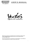
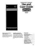
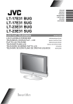
1
Instructions 50:1 Ratio Fire-Ball® Lubrication Pump Portable units for heavy grease. For professional use only. See page 2 for model information, including maximum working pressure and approvals. Important Safety Instructions Read all warnings and instructions in this manual. Save these instructions. These systems are designed to be used only in pumping non-corrosive and non-abrasive lubricants and grease. Any other use of the system can cause unsafe operating conditions and result in component rupture, fire, or explosion which can cause serious injury, including fluid injection. Model 240883 shown 307878Y EN Table of Contents Table of Contents Warnings . . . . . . . . . . . . . . . . . . . . . . . . . . . . . . . . . 3 Installation . . . . . . . . . . . . . . . . . . . . . . . . . . . . . . . . 5 Grounding . . . . . . . . . . . . . . . . . . . . . . . . . . . . . . 5 Models 225773, 225827, 240883, 240884, and 245695 . . . . . . . . . . . . . . . . . . . . . . . . . . . . . 5 Models 225006, 225026, 240880, 240881, and 245696 . . . . . . . . . . . . . . . . . . . . . . . . . . . . . 6 Models 222069, 240885, and 245694 . . . . . . . . 7 Models 222245 and 240882 . . . . . . . . . . . . . . . . 7 Models 226012 and 240886 . . . . . . . . . . . . . . . . 8 Typical Installation . . . . . . . . . . . . . . . . . . . . . . . 9 Air Line and Accessories . . . . . . . . . . . . . . . . . 10 Pressure Relief Procedure . . . . . . . . . . . . . . . . 10 Start-up: Single or Multiple Pump Systems . . . 10 Parts . . . . . . . . . . . . . . . . . . . . . . . . . . . . . . . . . . . . 12 Technical Data . . . . . . . . . . . . . . . . . . . . . . . . . . . . 17 Graco Standard Warranty . . . . . . . . . . . . . . . . . . . 18 Models Part No. Maximum Working Pressure psi (MPa, bar) Size 225006 120 lb 240880 † 120 lb 225026 120 lb 245696 120 lb 240881 † 120 lb 222245 120 lb 240882 † 120 lb 225773 35 to 50 lb 245695 5000 (35, 350) 35 to 50 lb 240883 † 35 to 50 lb 225827 35 to 50 lb 240884 † 35 to 50 lb 222069 25 to 50 lb 245694 25 to 50 lb 240885 † 25 to 50 lb 226012 50 lb 240886 † 50 lb † These models are CE Certified. 2 Base Type* Portable Portable 2-wheel truck 2-wheel truck 2-wheel truck 2-wheel truck 2-wheel truck 2-wheel truck 2-wheel truck 2-wheel truck 2-wheel truck 2-wheel truck Dispense Follow Cover Inductor Pail Kit Plate CE Installation Kit 240831 307878Y Warnings Warnings The following warnings are for the setup, use, grounding, maintenance, and repair of this equipment. The exclamation point symbol alerts you to a general warning and the hazard symbols refer to procedure-specific risks. When these symbols appear in the body of this manual or on warning labels, refer back to these Warnings. Product-specific hazard symbols and warnings not covered in this section may appear throughout the body of this manual where applicable. WARNING FIRE AND EXPLOSION HAZARD When flammable fluids are present in the work area, such as gasoline and windshield wiper fluid, be aware that flammable fumes can ignite or explode. To help prevent fire and explosion: • Use equipment only in well ventilated area. • Eliminate all ignition sources, such as cigarettes and portable electric lamps. • Keep work area free of debris, including rags and spilled or open containers of solvent and gasoline. • Do not plug or unplug power cords or turn lights on or off when flammable fumes are present. • Ground all equipment in the work area. • Use only grounded hoses. • Stop operation immediately if static sparking occurs or you feel a shock. Do not use equipment until you identify and correct the problem. • Keep a working fire extinguisher in the work area. EQUIPMENT MISUSE HAZARD Misuse can cause death or serious injury. • Do not operate the unit when fatigued or under the influence of drugs or alcohol. • Do not exceed the maximum working pressure or temperature rating of the lowest rated system component. See Technical Data in all equipment manuals. • Use fluids and solvents that are compatible with equipment wetted parts. See Technical Data in all equipment manuals. Read fluid and solvent manufacturer’s warnings. For complete information about your material, request MSDS from distributor or retailer. • Do not leave the work area while equipment is energized or under pressure. • Turn off all equipment and follow the Pressure Relief Procedure when equipment is not in use. • Check equipment daily. Repair or replace worn or damaged parts immediately with genuine manufacturer’s replacement parts only. • Do not alter or modify equipment. Alterations or modifications may void agency approvals and create safety hazards. • Make sure all equipment is rated and approved for the environment in which you are using it. • Use equipment only for its intended purpose. Call your distributor for information. • Route hoses and cables away from traffic areas, sharp edges, moving parts, and hot surfaces. • Do not kink or over bend hoses or use hoses to pull equipment. • Keep children and animals away from work area. • Comply with all applicable safety regulations. 307878Y 3 Warnings WARNING SKIN INJECTION HAZARD High-pressure fluid from dispensing device, hose leaks, or ruptured components will pierce skin. This may look like just a cut, but it is a serious injury that can result in amputation. Get immediate surgical treatment. • Do not point dispensing device at anyone or at any part of the body. • Do not put your hand over the fluid outlet. • Do not stop or deflect leaks with your hand, body, glove, or rag. • Follow the Pressure Relief Procedure when you stop dispensing and before cleaning, checking, or servicing equipment. • Tighten all fluid connections before operating the equipment. • Check hoses and couplings daily. Replace worn or damaged parts immediately. TOXIC FLUID OR FUMES HAZARD Toxic fluids or fumes can cause serious injury or death if splashed in the eyes or on skin, inhaled, or swallowed. • Read MSDSs to know the specific hazards of the fluids you are using. • Store hazardous fluid in approved containers, and dispose of it according to applicable guidelines. • Always wear chemically impermeable gloves when spraying, dispensing, or cleaning equipment. 4 307878Y Installation Installation Grounding Models 225773, 225827, 240883, 240884, and 245695 Refer to FIG. 2 for the following instructions. The equipment must be grounded to reduce the risk of static sparking and electric shock. Electric or static sparking can cause fumes to ignite or explode. Improper grounding can cause electric shock. Grounding provides an escape wire for the electric current. Ground all of this equipment: • Pump: Use a ground wire and clamp as shown in FIG. 1. Remove the ground screw (Z) and insert through the eye of the ring terminal at end of ground wire (Y). Fasten the screw back onto the pump and tighten securely. Connect the other end of the ground wire to a true earth ground. To order a ground wire and clamp, order P/N 222011. 1. Models 225773, 240883, and 245695 only : Assemble the truck as shown in the parts drawing on page 13. Secure the truck pail (5) to the truck base with the pointed hold-down clamps (3c) and thumb nuts (3d). 2. Models 225827 and 240884 only : Remove the fluid outlet adapter included with the pump, and screw the holster (6) into the pump outlet, using thread sealant. 3. Remove the cover (4) from the pail of lubricant. Place the pail of lubricant into the truck pail. 4. Secure the cover (4) on the pail with three thumbscrews (A). 5. Insert the pump riser tube through the top of the cover (4). Lower the pump until it rests on the cover. 6. Assembly the gun (2b) and hose (2a), and connect the hose to the pump fluid outlet. Z Y 7. Connect the nipple (2d) to the pump air inlet or air regulator (7b) inlet, whichever is applicable. 8. Connect the quick-disconnect coupler (2c) to the air supply hose. FIG. 1 • • Air and fluid hoses: Use only grounded hoses. 7b 2b Air compressor: Follow manufacturer’s recommendations. • Fluid supply container: Follow the local code. • To maintain ground continuity when flushing or relieving pressure, always hold a metal part of the fun firmly to the side of a grounded metal waste container, then trigger the gun. 2a 2c, 2d 6 4 A 5 3c, 3d Model 240883 shown FIG. 2 307878Y 5 Installation Models 225006, 225026, 240880, 240881, and 245696 Refer to FIG. 3 for the following instructions. 7b 2c, 2d 2a 2a 2b 1. Models 225006 and 240880 : Assembly the base (3) as shown in the Parts Drawing on page 14. Models 225026, 240881, and 245696 : Assemble the truck (3) as shown in the Parts Drawing on page 13. 6 4 5 2. Remove the fluid outlet adapter included with the pump, and screw the holster (6) into the pump outlet, using thread sealant. A 3 3. Place an open 120-lb (54.43 kg) drum of grease on mounting base or truck and secure it with the hold-down clamps. For portable base models 225006 and 240880: For steel drums use pointed end of bracket (3c). Position clamps above drum bead. Tight bolts (3b). For fiber drums reverse bracket (3c) to use flat end. For truck model 225026, 245696 and 240881: For steel drums: use pointed end of bracket (3c). Position clamp above drum bead. Tighten thumb nuts (3d). 3c, 3d 3b, 3c 4. Press the follow plate (5) down firmly onto the grease, and rotate it to eliminate air pockets and reduce channeling. 5. Insert the pump through the cover (4). 6. Slide the cover up far enough to let the pump pass easily through the follow plate grommet. 7. Secure the cover (4) on the drum with the thumb screws (A). It is not necessary to bolt the pump to the cover. Model 240881 shown FIG. 3 8. Assemble the gun (2b) and hose (2a), and connect the hose to the pump fluid outlet. 9. Connect the nipple (2d) to the pump air inlet or air regulator (7b) inlet, whichever is applicable. 10. Connect the quick-disconnect couple (2c) to the air supple hose. 6 307878Y Installation Models 222069, 240885, and 245694 Models 222245 and 240882 Refer to FIG. 5 for the following instructions. Refer to FIG. 4 for the following instructions. 1. Remove the cover from the pail and scoop the lubricant from the center to the sides of the pail to make its surface concave. 2. Center the follow plate (5) in the pail opening. Press the plate firmly downward and rotate it over the lubricant surface to eliminate air pockets and prevent channeling. 3. Place the cover (3a) on thep ail, and tighten the thumb screws (3f). 4. Assemble the gun (2b) and hose (2a), and connect the hose to the pump fluid outlet. 1. Assemble the cart (6). Use only 2 of the 4 brackets (5d) supplied. 2. Install the rear positions of the drum shelf (6b). 3. Press the follow plate (4) down firmly onto the grease, and rotate it to eliminate any air pockets and reduce channeling. Insert the pump through the cover (3). Slide the cover up far enough to allow the pump to pass easily through the follow plate grommet and into the grease. 4. Using items 5a to 5d, secure the cover to the drum, and the drum to the cart. It is not necessary to bolt the pump to the cover. 5. Assemble the gun (2b) and hose (3a), and connect the hose to the pump fluid outlet. 5. Connect the nipple (2d) to the pump air inlet or air regulator (7b) inlet, whichever is applicable. 6. Connect the quick-disconnect coupler (2c) to the air supply hose. 6. Connect the quick-disconnect nipple (2d) to the pump air inlet or air regulator (7b) inlet, whichever is applicable. 7. Connect the quick-disconnect couple (2c) to the air supply hose. 2b 2a 2b 7b 2c, 2d 2c 2d 2a 7b 3 6 5a 4 3f 5b 3a 5c 5d 5 Model 240885 shown FIG. 4 6b Model 240882 shown FIG. 5 307878Y 7 Installation Models 226012 and 240886 Refer to FIG. 7 for the following instructions unless other wise indicated. 1. Assemble the truck as shown in the Parts Drawing on page 13 but do not assemble the handle. 11. Center the inductor plate (5) in the pail opening. Press down on the pump and rock it back and forth to seat the inductor plate to eliminate air pockets. Continue action until material appears at the vent opening. 12. Close the inductor plate vent by turning the knob clockwise. 2. Slide handle through elevator slide tube and secure handle to base. 13. Assemble the gun (2b), Z-swivel, and hose (2a). 3. Remove the fluid outlet adapter included with the pump, and screw the holster (6) into the pump outlet using thread sealant. 14. Connect hose (2a) to holster (6) or to pump fluid outlet adapter if you chose not to use the holster.Connect the nipple (2d) to the pump air inlet or air regulator inlet (7b), whichever is applicable. 4. Secure pump to elevator mounting plate. 5. Remove inductor plate locking nut, locking ring, and o-ring. (FIG. 6) Locking ring 15. Connect the quick-disconnect coupler (2c) to the air supply hose. Pump riser tube Locking nut 2a 7b 2b 2c, 2d 6 5 Pump intake slots 1/8” (3 mm) 5 FIG. 6 6. In order, slide inductor plate locking nut, locking ring, and o-ring on pump riser tube. 7. Adjust the inductor plate (5) on the pump riser tube so the slots are showing just below the inside of the plate. Tighten the locking nut securely. (FIG. 6) 3c, 3d Model 240886 shown 8. Open the inductor plate vent by turning the knob counter clockwise. 9. Place an open 50 lb (22.68 kg) pail of grease on the truck and secure it with the hold-down clamps. FIG. 7 10. Remove the cover from the pail and scoop the lubricant from the center to the sides of the pail to make its surface concave. 8 307878Y Installation Typical Installation The installation shown below is only a guide for selecting and installing system components and accessories. Contact your Graco distributor for assistance in designing a system to suit your particular needs. D B J E C H F G A FIG. 8 Key: A B C D E F G H J K Fluid dispense line Pump ground wire (required) Air regulator Main air supply line Air filter Pump lubricator Pump runaway valve Bleed-type master air valve (required) Quick-disconnect couple and nipple Air regulator (7b) with safety valve (7c) and gauge (not shown) Included with Models 240880 to 240886 307878Y 9 Installation Air Line and Accessories NOTE: Install air line accessories in the order shown in the Typical Installation. • Install the air regulator (C) to control pump speed and pressure. • Install a pump runaway valve (G) to shut off the air to the pump if the pump accelerates beyond the pre-adjusted setting. A pump that runs too fast can be seriously damaged. • On the main air supply line from the compressor, install an air line filter (E) to remove harmful dirt and contaminants from the compressed air supply. • • Install an air line lubricator (F) for automatic air motor lubrication. For Models 240880 through 240886, install the provided air regulator/safety valve (K) at the pump air inlet with the nipple (7a, also included). • Install a bleed-type master air valve (H) to relieve air trapped between the valve and the motor when the valve is closed. NOTICE Avoid hanging air accessories directly on the pump air inlet. The fittings are not strong enough to support the accessories and may cause one or more to break. If accessories must be installed directly on the pump, provide a bracket on which to mount them. Trapped air can cause the air motor to cycle unexpectedly, causing serious injury if you are adjusting or repairing the pump. Follow the Pressure Relief Procedure on page 10. Operation Pressure Relief Procedure Start-up: Single or Multiple Pump Systems 1. Close the air regulator and bleed-type master air valves to all but one pump. 1. Shut off the air to the pump. 2. Open the master air valve from the compressor. 2. Bleed off the air pressure by closing the air regulator (self-relieving type), or closing the bleed-type master air valve installed upstream of the air regulator, or disconnecting the air supply hose at the quick-disconnect. 3. For the pump which is connected, trigger the dispensing valve into a grounded metal waste container, making firm metal-to-metal contact between the container and valve. 3. Hold a metal part of the gun or valve firmly to the side of a grounded metal waste container and trigger to relieve fluid pressure. 4. Open the bleed-type master air valve, and open the pump air regulator slowly until the pump is running. When the pump is primed and all air has been pushed out of the lines, release the trigger. 5. If you have more than one pump, repeat this procedure for each pump. NOTE: When the pump is primed, and with sufficient air supplied, the pump starts when the dispensing valve is opened and shuts off when it is closed. 10 307878Y Installation 6. Set the air pressure to each pump at the lowest pressure needed to get the desired results. NOTE: A pump runaway valve can be installed not he air line to automatically shut off the pump if it starts to run too slow. Never allow the pump to run dry of the fluid being pumped. A dry pump will quickly accelerate to a high speed, possibly damaging itself. If the pump accelerates quickly or is running too fast, stop it immediately and check the fluid supply. If the supply container is empty and air has been pumped into the lines, prime the pump and lines with fluid, or flush it and leave it filled with a compatible solvent. Be sure to eliminate all air from the fluid system. The maximum working pressure of each pump in your system may not be the same. To reduce the risk of over-pressurizing any part of your system, be sure you know the maximum working pressure rating of each pump and its connected components. Never exceed the maximum working pressure of the lowest rated components connected to a particular pump. To determine the fluid output pressure using the air regulator reading, multiply the ratio of the pump by the air pressure down on the regulator gauge. For example: 50:(1) ratio x 100 psi air = 50000 psi fluid output 50:(1) ratio x 0.7 MPa air = 35 MPa fluid output 50:(1) ratio x 7 bar air = 350 bar fluid output Limit the air to the pump so that no air line or fluid line component or accessory is over pressurized. 7. Read and follow the instructions supplied with each component in the system. 8. When shutting off the system, always follow the Pressure Relief Procedure on page 10. 307878Y 11 Parts Parts Ref No 2, Dispense Kit 222070 Ref. 2a 2b 2c 2d 2e Part No. 109151 242056 114558 169971 202577 Description HOSE, 1/4 npt (mbe), 12 ft (3.7 m) VALVE COUPLER, quick-disconnect NIPPLE, quick-disconnect Z-SWIVEL 2b Qty . 1 1 1 1 1 2c 2e 2d Ref No. 2 2a Model 225827, 240884: 35 lb to 50 lb pail size Ref. 1 2 3 4 6 7 Part No. Description 239877 PUMP, 50:1 Fire-Ball, See manual 308883 for parts 222070 DISPENSE KIT, See parts list above 204134 PAIL 24N924 COVER, See manual 306345 for parts, model 225827 24R350 COVER, See manual 306345 for parts, model 240884 203976 HOLSTER 240831 CE INSTALLATION KIT, See parts list on page 16, model 240884 Qty . 1 1 1 7 1 1 4 6 1 3 1 1 2 Model 222069, 245694, 240885: 25 lb to 50 lb pail size Ref. 1 2 3 3a 3b 3c 3d 3e 3f 3g 3h 5 7 12 Part No. Description 239877 PUMP, 50:1 Fire-Ball, See manual 308883 for parts 222070 DISPENSE KIT, see parts above 245697 DISPENSE KIT, Model 245694 only, See parts list on page 14 222059 COVER, includes items 3a- 3h 207617 COVER, pail 168102 PLATE, stop, pump 158048 BUMPER, button, rubber 159608 RIVET 150868 HOLDER, gun 100200 SCREW, thumb 100025 NUT, 1/4 npsm thd 100579 PIN, cotter, 1/8” x 1” 220653 FOLLOW PLATE, See manual 306345 for parts, model 240885 24F901 FOLLOW PLATE, see manual 306345, models 222069, 245694 240831 CE INSTALLATION KIT, See parts list on page 16, model 240885 Model 240884 shown Qty . 1 1 1 1 1 1 1 1 1 3 1 1 1 Model 240885 shown 1 2 7 3b 3a 3f 5 3d 3c 3h 3e 1 1 307878Y Parts Model 225026, 245696l, 240881: 120 lb drum size Ref. Part No. Description 1 239887 PUMP, 50:1 Fire-Ball, See manual 308883 for parts 2 222070 DISPENSE KIT, See parts, page 12 245697 DISPENSE KIT, Model 245696 only, See parts, page 14 3 203650 TRUCK, 2 wheel, See parts below 4 204574 COVER, See manual 30345 for parts, models 245696, 240881 24R350 COVER, See manual 30345 for parts, model 255026 5 220654 FOLLOW PLATE, See manual 306345 for parts, model 245696, 240881 220654 FOLLOW PLATE, See manual 306345 for parts, model 255026 6 203976 HOLSTER 7 240831 CE INSTALLATION KIT, See parts on page 16, model 240881 Qty . 1 1 7 2 4 1 1 6 5 1 1 3 1 1 1 Model 240881 shown 1 1 Model 225773, 245695, 2480883: 35 lb to 50 lb pail size 3 1 7 2 Ref. Part No. Description Qty 1 239877 PUMP, 50:1 Fire-Ball, See manual 1 308883 for parts 2 222070 DISPENSE KIT, See parts, page 12 1 245697 DISPENSE KIT, Model 245696 only, 1 See parts, page 14 3 203650 TRUCK, 2 wheel, See parts below 1 4 204574 COVER, See manual 306345 for 1 parts, models 245695, 240883 24F901 COVER, See manual 306345 for 1 parts, model 225773 5 204134 PAIL 1 6 203976 HOLSTER 1 7 240831 CE INSTALLATION KIT, See part list 1 on page 16, models 240883 4 6 5 Model 240883 shown Ref No. 3, Truck 203650 . Ref. 3a 3b 3c 3d Part No. 203651 101251 159912 159913 3e 3f 3g 3h 154636 100609 101242 159924 307878Y Description BASE, truck, bare WHEEL NUT, thumb, 5/16-18 CLAMP, hold down, steel drums only WASHER, 5/8”, 16 GA SCREW, rd nd mach, 1/4-20 x 3/8” RING, retaining HANDLE, truck Qty . 1 2 2 2 4 2 2 1 3h 3a 3d 3c 3b 3e 3f 3e 3g Ref No. 3 13 Parts Model 225006, 240880: 120 lb drum size 1 Ref. Part No. Description Qty. 1 239887 PUMP, 50:1 Fire-Ball, See manual 1 308883 for parts 2 222070 DISPENSE KIT, See parts, page 12 1 3 203622 PORTABLE BASE, See parts list 1 below 4 204574 COVER, See manual 306345 for 1 parts, model 240880 24R350 COVER, See manual 306345 for 1 parts, model 225006 5 220654 FOLLOW PLATE, See manual 1 306345 for parts, model 240880 5 24F902 FOLLOW PLATE, See manual 1 306345 for parts, model 225006 6 203976 HOLSTER 1 7 240831 CE INSTALLATION KIT, See parts 1 on page 16, model 240880 2 7 4 6 5 3 Model 240880 shown 3b 3d 3e 3c 3a Ref No. 3, Portable Base 203622, Series B Ref. 3a 3b 3c 3d 3e 3f 3g Part No. 191750 102547 191747 100214 100132 113660 113646 Description BASE, drum BOLT, hex hd, 5/16”-18 x 1.5” BRACKET WASHER, lock WASHER, flat RIVET CASTER, polyurethane Qty . 1 2 2 2 2 16 4 3f 3g Ref No. 3 Ref No. 2, Dispense Kit 245697 Ref 2a 2b 2c 2d 2e Part No. 109151 233807 114558 169971 202577 Description HOSE, 1/4 npt(mbe), 12 ft (3.7 m) VALVE COUPLER, quick-disconnect NIPPLE, quick-disconnect Z-SWIVEL 2b Qty . 1 1 1 1 1 2d 2c 2e 2a 14 Ref No. 2 307878Y Parts Ref No. 2, Dispense Kit 222838 2b Ref 2a 2b 2c 2d 2e Part No. 109154 242056 114558 169971 202577 Description HOSE VALVE COUPLER, quick-disconnect NIPPLE, quick-disconnect Z-SWIVEL 2d 2c Qty 1 1 1 1 1 2e Ref No. 2 2a Model 222245, 240882: 120 lb drum size Ref 1 2 3 4 5 5a 5b 5c 5d 6 6a 6b 6c 6d 6e 6f 6g 6h 6j 6k 6m 6n 6p 7 Part No. Description 239887 PUMP, 50:1 Fire-Ball, See manual 308883 for parts 222383 DISPENSE KIT, See parts list above 222060 COVER, See manual 306345 for parts 220654 FOLLOW PLATE, See manual 306345 for parts, model 240882 24F902 FOLLOW PLATE, See manual 306345 for parts, model 222245 222061 HOLD DOWN KIT, Includes items 5a to 5d 200889 NUT, wing 153166 HOOK, drum mounting 153102 ROD, drum 159016 BRACKET, retaining (2 used) 222243 CART KIT, includes items 6a to 6p 218027 FRAME, cart 183987 SHELF, drum 107144 SCREW, cap, 3/8-16 x2-1/4 179766 HANDLE, cart 100731 WASHER, flat, 3/8 101566 LOCKNUT, hex, 3/8-16 179770 AXLE 154628 WASHER, flat, 3/4 107146 RING, retaining, ext, 3/4 106039 WHEEL, tire, pneumatic 107145 CAP, tube 100680 CAPSCREW, 3/8-16 x 7/8 159016 BRACKET, retaining 240831 CE INSTALLATION KIT, See part list on page 16, model 240882 307878Y Qty . 1 6d 1 2 1 6e 1 6m 7 6f 6c 1 3 1 1 2 2 2 4 1 2 1 4 1 6 6 1 4 4 2 2 2 2 1 4 5a 5b 5c 6j 5d 6a 6h 6g 6b 6n 6p 6e 6f 6k 6h 6j 15 Parts Model 226012, 240886: 50 lb pail size 3 Ref. Part No. Description Qty. 1 239877 PUMP, 50:1 Fire-Ball, See manual 1 308883 for parts 2 222070 DISPENSE KIT, See parts, page 1 12 3 203650 TRUCK, portable, See parts list on 1 page 13 4 203664 ELEVATOR 1 5 204351 FOLLOW PLATE 1 6 203976 HOLSTER 1 7 240831 CE INSTALLATION KIT, See parts 1 list below, model 240886 1 4 7 2 6 5 Model 240886 shown Ref No. 7, CE Installation Kit 240831 Ref. 7a 7b 7c 7d 7e Part No. 156849 109075 103347 222011 † Description NIPPLE REGULATOR, air, with gauge VALVE, safety CLAMPING, grounding CE Label Qty. 1 1 1 1 1 7d 7a † ATTENTION: To comply with CE directives, the CE identification label must be affixed to the back of the cart or to the top of the drum cover. Permanently mark the date of the assembly on the label. 7b 7c 7e Ref No. 7 16 307878Y Technical Data Technical Data . 50:1 Ratio Fire-Ball Lubrication Pumps US Maximum fluid working pressure 5000 psi Maximum Air Inlet Pressure 100 psi Sound (dBa) Tested at 100 psi (0.7 MPa, 7 bar) at 40 cycles per minute Sound Pressure Level, measured at 1 meter from unit Sound Power Level, tested in accordance with ISO 9614-2 307878Y Metric 35 MPa, 350 bar 0.7 MPa, 7 bar 77.9 dB(A) 85.6 dB(A) 17 Graco Standard Warranty Graco warrants all equipment referenced in this document which is manufactured by Graco and bearing its name to be free from defects in material and workmanship on the date of sale to the original purchaser for use. With the exception of any special, extended, or limited warranty published by Graco, Graco will, for a period of twelve months from the date of sale, repair or replace any part of the equipment determined by Graco to be defective. This warranty applies only when the equipment is installed, operated and maintained in accordance with Graco’s written recommendations. This warranty does not cover, and Graco shall not be liable for general wear and tear, or any malfunction, damage or wear caused by faulty installation, misapplication, abrasion, corrosion, inadequate or improper maintenance, negligence, accident, tampering, or substitution of non-Graco component parts. Nor shall Graco be liable for malfunction, damage or wear caused by the incompatibility of Graco equipment with structures, accessories, equipment or materials not supplied by Graco, or the improper design, manufacture, installation, operation or maintenance of structures, accessories, equipment or materials not supplied by Graco. This warranty is conditioned upon the prepaid return of the equipment claimed to be defective to an authorized Graco distributor for verification of the claimed defect. If the claimed defect is verified, Graco will repair or replace free of charge any defective parts. The equipment will be returned to the original purchaser transportation prepaid. If inspection of the equipment does not disclose any defect in material or workmanship, repairs will be made at a reasonable charge, which charges may include the costs of parts, labor, and transportation. THIS WARRANTY IS EXCLUSIVE, AND IS IN LIEU OF ANY OTHER WARRANTIES, EXPRESS OR IMPLIED, INCLUDING BUT NOT LIMITED TO WARRANTY OF MERCHANTABILITY OR WARRANTY OF FITNESS FOR A PARTICULAR PURPOSE. Graco’s sole obligation and buyer’s sole remedy for any breach of warranty shall be as set forth above. The buyer agrees that no other remedy (including, but not limited to, incidental or consequential damages for lost profits, lost sales, injury to person or property, or any other incidental or consequential loss) shall be available. Any action for breach of warranty must be brought within two (2) years of the date of sale. GRACO MAKES NO WARRANTY, AND DISCLAIMS ALL IMPLIED WARRANTIES OF MERCHANTABILITY AND FITNESS FOR A PARTICULAR PURPOSE, IN CONNECTION WITH ACCESSORIES, EQUIPMENT, MATERIALS OR COMPONENTS SOLD BUT NOT MANUFACTURED BY GRACO. These items sold, but not manufactured by Graco (such as electric motors, switches, hose, etc.), are subject to the warranty, if any, of their manufacturer. Graco will provide purchaser with reasonable assistance in making any claim for breach of these warranties. In no event will Graco be liable for indirect, incidental, special or consequential damages resulting from Graco supplying equipment hereunder, or the furnishing, performance, or use of any products or other goods sold hereto, whether due to a breach of contract, breach of warranty, the negligence of Graco, or otherwise. FOR GRACO CANADA CUSTOMERS The Parties acknowledge that they have required that the present document, as well as all documents, notices and legal proceedings entered into, given or instituted pursuant hereto or relating directly or indirectly hereto, be drawn up in English. Les parties reconnaissent avoir convenu que la rédaction du présente document sera en Anglais, ainsi que tous documents, avis et procédures judiciaires exécutés, donnés ou intentés, à la suite de ou en rapport, directement ou indirectement, avec les procédures concernées. Graco Information For the latest information about Graco products, visit www.graco.com. TO PLACE AN ORDER, contact your Graco distributor or call to identify the nearest distributor. Phone: 612-623-6928 or Toll Free: 1-800-533-9655, Fax: 612-378-3590 All written and visual data contained in this document reflects the latest product information available at the time of publication. Graco reserves the right to make changes at any time without notice. For patent information, see www.graco.com/patents. Original instructions. This manual contains English. MM 307878 Graco Headquarters: Minneapolis International Offices: Belgium, China, Japan, Korea GRACO INC. AND SUBSIDIARIES • P.O. BOX 1441 • MINNEAPOLIS MN 55440-1441 • USA Copyright 1988, Graco Inc. All Graco manufacturing locations are registered to ISO 9001. www.graco.com Revised May 2014