1
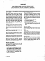
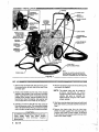
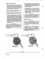
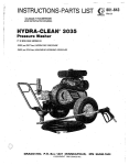
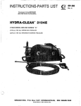
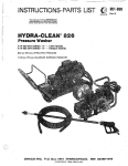
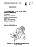
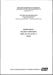
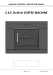
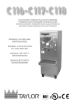
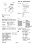
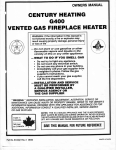
INSTRUCTIONS-PARTS LIST
This manual contains IMPORTANT
WARNINGS and INSTRUCTIONS
READ AND RETAIN FOR REFERENCE
e
802-776,
GRACO
HYDRAlCLEAN 826
Pressure Washer
c
GRACO INC. P.O. BOX 1441 MINNEAPOLIS, MN 55440-1444
@COPYRIGHT 1987 GRACO INC.
.. .
,
.
. .
.
. .
.. .
,
.
.
... .... .~ ~
.. .
.
.
.
, ..
.I'.r7r
,,..>.
.. .!...
.. :..i .:.
..._.
.,..
a.
. . ... :,i
,,:'
..>.;,;
',
,
.)
, ?':
WARNING
HIGH PRESSURE SPRAYCAN CAUSE SERIOUS INJURY.
FOR PROFESSIONALUSE ONLY. OBSERVE ALL WARNINGS.
Read and understand all instructionmanuals before operating equipment.
FLUID INJECTION HAZARD
General Safety
This 'pressure washer generates very high fluid
pressure. Spray from the gun, leaks or ruptured
components can inject fluid through your skin and
into your body and cause extremely serious bodily
injury, including theneed for amputation. Also, fluid
injected or splashed into theeyes oron the skin can
cause serious damage. In addition, some cleaning
solutions maybetoxicandcancausechemicalburns,
skin irritations, and allergic reactions if inhaled orif
they come in contact with the body or eyes. Always
follow these precautions when operating your
pressure washing system to reduce the risk of
serious bodily injury.
NEVERpointthespraygunatanyoneoratanypartof
the body. NEVER use the spray gun without the
wand. NEVER put hand or fingers over the spray tip.
NEVER try to stop or deflect leaks with your hand or
body.
.
ALWAYS be sure equipment safety devices are
operating properly before each use.
Use this pump only for pumping water and waterdiluted cleaning solutions. NEVER use the pump for
paint or.any other coatings.
ALWAYS wear protective eyewear and appropriate
clothing to protect yourself from the overspray and
the debris that is removed as you clean.
Read and follow the cleaning chemical
manufacturer's recommendations on preparation
and use of the cleaning solution, and the use of
breathing apparatus and proper ventilation.
MEDICAL TREATMENT
If any fluid appears to penetrate your skin, get
EMERGENCY MEDICAL CARE AT ONCE. DO
NOT TREAT AS A SIMPLE CUT. Tell the doctor
exactly what fluid was injected.
Note To Physician: Injection in the skin is a
traumatic injury.' It is important to treat the
injury surgically as soon as possible. Do not
delay treatment to research toxicity. Toxicityisa
concern with some exotic coatings injected
directly into thebloodstream. Consultation with
a plastic surgeon . or reconstructive hand
surgeon may be advisable.
2
802-776
Pressure Relief Procedure
To reduce the riskof serious bodily injury, including
fluid injection and splashing in the eyes, or on the
skin, always follow this procedure whenever you
shut off the pump, when checking or servicing any
part of the system. when installingor changing spray
tips, and whenever you stop spraying for more than
10 minutes.
1.
2.
3.
4.
Engage the guntrigger safety latch.
Turn pressure washer OFF.
Remove the power cord from outlet.
Shut off the water supply.
5. Disengage the trigger safety latch andtriggerthe
gun to relieve pressure, and engage the latch
again.
Spray Gun Safety
Do not remove or modify any pait of the gun; this can
cause a malfunction and result in serious bodily
injury.
Safety Latch
ALWAYS engagethe gun safetylatchwhenever you
stopcleaning,evenforamoment.ThelatchMUSTBE
pushed fully down to make the gun inoperative.
Failure to properly set the safety latch can result in
accidental triggering of the gun. See Figure 2. page 6.
Spray Tip Safety
Use extreme caution when cleaning or changing
spray tips. If the spray tip clogs while spraying,
engage the gun safety latch immediately. ALWAYS
follow the Pressure Relief Procedure and then
remove the spray tip to clean it.
EQUIPMENTMISUSE
HAZARD
General Safety
Any misuse of the pressure washer or accessories,
such as overpressurizing, modifying pans, using
incompatible chemicals and fluids, or using worn or
damaged pans, can cause them to rupture and result
in fluid injection, splashing in the eyes oron theskin,
or other serious bodily injury or propeny damage.
NEVER alter or modify any pan of this equipment,
doing so could cause it to malfunction.
CHECK allcleaningequipment regularlyandrepairor
replace worn or damaged pans immediately.
If using a chemical injector,. read and follow the
chemical manufacturer's literatureregarding the use
of protective eyewear, clothing andequipment.
System Pressure
This sprayer can develop 1100 psi (76 bar)
MAXIMUM WORKING PRESSURE. Be sure that all
spray equipment and accessories are rated to
withstand the maximum working pressure of this
sprayer. DO NOT exceed the maximum working
pressure of anycomponent or accessoryused in the
system.
Chemical Compatibility
BE SURE that all chemicals used in the chemical
injector are compatible with the wetted partsof the
hose, gun. wand and tip, as given in the Technical
Data on the back cover. Always read the chemical
manufacturer's literature before using any chemical
in this pressure washer.
HOSESAFETY
High pressure fluid in the hoses can be very
dangerous. If the hose develops a leak, split or
rupture due to any kind of wear, damage or misuse.
the high pressure spray emitted from itcan cause a
fluid injection injury or other serious bodily injury or
propeny damage.
TIGHTEN all fluidconnections securely before each
use.Highpressurefluidcandislodgealoosecoupling
or allow high pressure spray to be emitted from the
coupling.
c
.~
NEVER use a damaged hose. Before each use, check
entire hose for cuts, leaks, abrasion, bulging cover, or
damage or movement of the hose couplings. If any of
these conditions exist, replace the hose immediately.
DO NOT try to recouple high pressure hose or mend it
with tape orany other device.Arepaired hosecannot
contain the highpressure fluid.
HANDLE AND ROUTE HOSES CAREFULLY.-Do not
pull on hoses to move the pressure washer. Do not
use chemicals which are not compatible with the
inner tube and cover of the hose. DO NOT expose
Graco hose to temperatures above 20OoF (94'C) or
below -4OOF (-4OOC).
ELECTRlCAL HAZARD
NEVER operate the pressure washer without the unit
being properly grounded. This includes internal
wiring on unit, plug (ground plug must be intact), and
building wiring. Because water is a natural
conductor, it is very Fmportant to provide a good
ground circuit to avoid serious bodily injury if
equipment should fail.
MOVING PARTS HAZARD
Moving panscan pinch or amputate your fingers or
other body parts. KEEP CLEARof moving pans when
starting or operating thepressurewasher. Followthe
Pressure Relief Procedure, page 2. before checking
or servicing the pressure washer to prevent
discharging high pressure fluid from thegun.
IMPORTANT
United States Government safety standards have
been adopted under the Occupational Safety and
Health Act. These standards-particularly
the
General Standards, Pan 1910, andthe Construction
Standards, Part 1926-should be consulted.
WARNING: Alerts user to avoid or
conditions that could cause bodily injury.
correct
CAUTION: Alerts user to avoid or correct
conditions that could cause damageto or destruction
of equipment.
NOTE: Identifies helpful procedures and
information.
802-776
,
..
3
....._. _..
.,:'
I
,. ... .....
..,
..
I
ASSEMBLYANSTALLATION
SET-UP
1. Remove the two hood bolts, flats and locks, from
the center bottom of eachside of the hood. Pivot
the hood open.
2. Position the handle into the end of the chassis
closest to the wheels. Line up the four mounting
holes. Install the four 3/8 x 1 inch bolts from the
outside of the chassis. Useflat washers only on
head of bolt. Usea flat washer, lock washer, and
nut oneach bolt on the insideof the chassis.
3. Connect one end of the 30 foot high pressure
hose to thepump outlet. This connection is made
with a threaded swivel fitting. Connect the other
end to the gun using the quick couplers provided.
CAUTION
Using longer hoses may affect sprayer
performance, and chemical injector
performance.
4
mzn6
.. .. .
4. Remove the plastic plug fromthe top of the pump
and install the dipstick.
NOTE: The plastic plug may he reused to
prevent splashing oil when
transporting the pressure washer in a
vehicle. Be sure to reinstall the
dipstick before using theunit to allow
proper venting.
5. Hood maynow be closed and secured with hood
bolts, flat washers, and lock washers removed in
Step 1 .
6. Remove the plastic plug from the inlet hose.
Check the water supply flow rate (see page 5).
Connect inlet hose to water supply. A standard
5/8 I.D. garden hose maybe usedto connect inlet
hose to thewater supply.
-~
j
I
Water Supply
..
CAUTION
Before connecting the water supply to the
pump, check your
local plumbing code
regarding cross-connection to the water
supply.
A backflow preventor, Part No. 801-133. is
available to prevent the back flow of
contaminated water intothefresh watersupply.
Install upstream from thepump.
DO NOT exceed 160°F (70T) inlet water
temperature.
Higher temperatures will damage the pump
packings.
A. Check flow rate of the water supply. It mus
be at least 3 gpm or the pressure washer will
not develop full pressure.
..
'
,..
.
..
.
E. To check flow rate, time how long it takes to
fill a standard five gallonpail; it should take
no longer than 1 minute and 40 seconds.
Electrical Supply
7. Connect the power cord to the proper 'power
supply. The electrical service required is single
phase, 115V. 60 Hz AC, 15 Amp. Electrical
service must include a ground wire. If an
extension cord is used, it must have a ground
wire and be at least No. 14 gage wire. Extension
cord must not be over 100 feet long.
START-UP
Use this procedure each time you start the pressure
washer to help ensure the pressure washer is ready
to operate and that you start it safely.
c
1 . Check pump oil level. Look at oil level indicator
window through inspection hole in side of. the
hood. Pump also has a dipstick located under
hood on top of pump. Oil level should be up todot
on oil level indicator window and within the
notch on dipstick. AddSA€ 20 or 30-weight nondetergent oil as necessary.
2. Connect pressure washer to water supply and to
'proper electrical service as described in set-up.
3. Turn water supply on and trigger the gun until
water sprays from the tipand all air is purged
from the system.
4. Press start bunon oncontrol panel,
NOTE: Avoid pressing start button when unit
is not plugged in because the stop
button cannot be pushedunlessunitis
plugged in. Always use motor control
switch when starting and stopping
unit.
5. Always engage the gun's trigger safety latch
whenever you stop spraying, even
for a moment,
to reduce the riskof fluid injection orsplashing in
the eyes or on the skin if the gun isbumped or
triggered accidentally.
6. Most pressure washer spraying is done at full
C
pressure. If a reduced pressure is desired for a
special application, there are two methods to
reduce the maximum output from thepressure
washer.
a. Turn the pressure control knob on the
unloader counterclockwise, as needed. This
method is best if you are operating
consistently at a reduced pressure.
b. Turn chemical selector valve to the "OFF"
position, then open the adjustable nozzle on
the end of the spray wand, as needed. This
method is best to quickly reduce pressure for
a special application.
when the spray gun isin use. Be sure that the
safety latch on thegun isin the "ON" position
before adjusting to avoid seriousbodily injury or
7. Always observe the following cautions to help
avoid costly damage to your pressure washer,
CAUTION
DO NOT allow thepressure washer to idle for
more than 10 minutes. The unit is equipped
with a thermal relief valve to help avoid the
recirculating water from becoming too hot and
seriously damaging the pump, but it is a good
idea to turn the
pressure washer off if you are
not spraying or cleaning at least every 10
minutes.
DO NOT run thepump dry, which will quickly
damage the pump. Be sure thewater supply is
fully turned on before starting the pump.
DO NOT operate the pressure washer with the
inlet screen removed. This screen helps keep
abrasive sediment out of the pump, which could
clog or scratch the pump.
DO NOTpumpcaustic materials; such materials
may corrodethe pump components.
Chemical Injector Opsration
. . .
8. Be sure that the control ring oninjector
ihe is
open two full turns from
the closed position. To
check this, the hood must be opened. Once the
control ring is open, it may be left alone. The
chemical mixture is controlled by thechemical
metering valves on thecontrol panel.
9. Place the chemical strainer@) and chemical
line(s1 into your chemical container(s).
10. Select which chemical i o u want touse with the
chemical selector valve on thecontrol panel.
11. To apply the cleaning chemical to the work
surface, the adiustable nozzle on the endof the
spray wand must be open. Thechemical(s) can
only be drawn into thewater stream, and applied
to the worksurface in a low pressure situation.
By opening the adjustable nozzle you create low
pressure. Closing it produces high pressure for
rinsingandpre-chemicalflushingornochemical
cleaning. One chemical may be turned off and on
at the gun by using the adjustable nozzle as
described above.
when the spray gun isin use. Be sure thatthe
safety latch on the gun is in "ON"
the position
before adjusting to avoid serious bodily injuryor
12. Adjust thechemical mixture(s) with thechemical
metering valve(s)on the controlpanel. Oncethe
chemical metering valve(s) are adjusted to the
desired setting, they may beleft therefor future
chemical applications.
13. To change to the other chemical, turn the
chemical selector valve to theother chemical. To
shut off chemical, turn the chemical selector
valve to the "OFF" position, or close the
adjustable nozzle. The chemical metering
valve@)do not have to be closedto change orshut
off chemical supply.
the wettedparts shown in the technical data at
the end of this manual to avoid serious damage
to theoressure washer and comoonents.
Trigger Safety Latch
WARNING
of serious bodily injury,
including fluid injection. splashing in the eyes
or on the skin, ALWAYS engage the trigger
safety latch whenever you stop spraying, even
for a moment.
In the engage position, the trigger safety latch
prevents the gun
from being triggered
accidentally by hand or if it is dropped or
bumped. Be sure thelatch isfullyseated inslot
in handle or it cannot prevent the gun
from
being triggered. See Figure 2.
a
TRIGGER SAFETY LATCH
SHOWN ENGAGED
6
802-776
... , .
,
SHUTDOWN. FLUSHING, AND STORAGE
~...
1:
C
After using the chemical injector system, it
should be flushed out with water or a 50%
antifreeze solution if unit will be exposed to
freezing temperatures. This is best done by
replacing the chemical container@)with a bucket
of water or a 50% antifreeze solution. Operate
pressure washer as described in start-up. Draw
water or antifreeze solution into both chemical
lines until it passes through the injector. By
flushing the chemical injector system, you will
help avoid unnecessary wear and prolongthe life
of components.
:
CAUTION
thaw it in a warm roombefore trying to start it.
Do not pour hot water on thepump; it maycrack
3. After each use, wipe all surfaces of the pressure
washer with a clean, damp cloth.
4. Perform the appropriate maintenance. See the
chart on page 7.
ObSeNing regular maintenance intervals helps
ensure that you get maximum performance and life
from your pressure washer.
There is a break-in period for the pump. After
changing the oil after the pump's break-in period, the
interval between required changes is longer.
If you are operating in dusty conditions, these
maintenance checks should be made more often.
.
temperatures, drain all waterout of the pump. If '
you must store the pressure washer in freezing
temperatures, flush it with a 50% antifreeze:
solution. This can be done by placing the end of,
the inlet hose into a bucket of 50% antifreeze
solution. Start thepressure washer. Triggerthe :
gun for 10 seconds, release the trigger for 10
seconds. Trigger and release about 10 times or
until the 50% antifreeresolutioncomes out ofthe
spray tip.
Pressure Relief Procedure
To reduce the risk of serious bodily injury.
including fluid injection and splashing in the
eyes, or on the skin, ALWAYS follow this
procedure whenever you shut off the pump,
when checking or sewicing any part of the
system, when installing or changing spray tips,
and whenever you stop spraying for more than
10 minutes.
1. Engage the guntrigger safety latch.
2. Turn the pressure washer off.
3. Removethe power cord from the outlet.
4. Shut off water supply.
5. Disengage the triggersafetylatchandtrigger
the gun torelieve pressure, and engage latch
again.
..
2. If the pressure washerwill beexposedtofreezing '
WARNING
INTERVAL
I
I
WHAT TO DO
I Clean water inlet screen.
Dailv
I
Check pump oil level.
Fill as necessarv.
After first
Change pump break-in oil.
50 hours of Use SAE
20W or 30W
Each 500.hours
of operation or
I
Pump
I
I
Change pump oil.
Use SAE20W or 30W
OILCAPACITY
10.1-Or.
(.3 liters)
I
TYPE
SA€ 20Wor 30W
Non-Detergent
C
802-776
.
. .~.
~
P
P
7
. . .. .
. .. .
~.
.
,
TROUBLESHOOTING CHART
WARNING
To reduce the riskof serious bodily injury, including fluid injection, splashing in the eyes oron the skin, or
injUryfrOmmOVingparts, alwaysfollowthe Pressure Relief Procedurewarning on
page7beforeproceeding.
CAUSE
PROBLEM
Low Pressure
.
Worn nozzle.
Coupling slippage.
Air leak in inlet plumbing.
:
, .
Inlet filterclogged.
Water leakagefrom under
the manifold.
Water in pump crankcase.
Frequent or premature
failure of the packing.
Worn packings.
Oil seal leaking.
May be caused byhumid air
condensing into water inside
the crankcase.
Replace packings.
Replace oil seals.
Change oil at 3 month or 500 hour intervals.
Scored, damaged, or worn
plungers.
Abrasive material in the water
being pumped.
Inlet water temperature too
nigh.
Over pressurizing pump.
Replace plungers.
3cessive pressure dueto
~artiallyplugged or damagedtip
lump running toolong
Nithout spraying or cleaning.
qunning pump dr$
Foreign particles in the inletor
jischarge valve, orworn inlet
tnd/or discharoe valves
Jnit notplugged in.
2.F.I.C. activated.'
Strong surging atthe inlet
and low pressure on the
discharge side.
Unit will not start.
. . . . . .
ilenric motor overheated
ilectric sewiceoff.
:hemica1 injector clogged.
Chemical injection system
doesn't work.
Wjunable nozzle completely
:losed.
.ow chemical level.
8 ' 802-776
.
;
. . .
. . , .
lighten or replace.
Disassemble. reseal, replace bad parts,
and reassemble.
Clean. Use adequate size. Check more
frequently.
Install proper filter. Check flow available to
pump. Replace packings.
Worn packing. Abrasivesin
pumped fluid or severe cavitation. Inadequate water supply.
Fouled or dirty inlet or disClean inlet and discharge valve assemblies.
charge valves.
Worn inletor discharge valves. Replace worn valves and/or discharge hose.
Leaky discharge hose.
Pressure adjustmentset down. Turn adjustment knobin to increase
pressure.
Restricted inlet or air
Proper size inlet plumbing; check for air
tight seal.
entering the inlet plumbing.
Inlet restrictions and/or air
Clean out foreign material, replace worn
leaks. Stuck inlet or discharge
valves.
valve.
Leaking high pressure seals.
Replace seals
Check flow available to pump.
Inadequate water supply.
Worn packings.
Replace packings.
Pump runs extremely
rough, pressure low.
.
.3
Install proper inlet filter.
Check inlet water temperature; be
sure not toexceed 160°F.
Do not modify any factory-set
adjustments.
Clean or replacetip.
Never run pump morethan 10
minutes without spraying or cleaning.
Do not run pump without water.
Replace or clean valves.
Check power cord.
Check for proper grounding.
Push Switch ON (RESETI button.
St motor cool and push reset button
,n motor.
:heck fusehircuit breaker panel.
Jisassemble chemical valve and clean.
;heck and clean chemical hose and filter.
[urn control ringon nozzle clockwise
o cause dropin pressure.
:heck level of chemical.
....
.
.
31
.
. ...
c
PUMP SERVICE
. .
WARNING
To reduce the riskof serious bodily injury. including fluid injection. splashing in the eyes or on the skin, or
.injury from moving parts, always follow the Pressure Relief Procedure Warning on page 7 before
proceeding.
~~
NOTE: The following metric wrenchesare needed: M6, M10, M30 Allenwrenches.
A pump repair.tool kit, P/N 800-271, is available, It includes packing, extraction and insenion tools.
Repair kits are available. Refer to theindividual repairsections, andthepans page for moredetails. For
the best results, use all the parts in the kit.
Valves
NOTE:
. .
To replace valves, orderkit part no. 801 472.
1. Remove the hex plug (205) from the manifold
(206) usinga n M30 wrench.
2. Carefully pull the packing retainer (212)fromthe
manifold. Examine the O-ring (213)andreplace it
if it is cut or damaged.
3. Remove the v-packing (210) and head ring (209).
Pull out the intermediate retainer ring (211).
Remove the v-packing (210) and head ring (209).
2. Examine the O-ring (204) under the plug and
replace it if it is cutor distorted,
4. Inspect all pansand replace as necessary.
3. Remove the valve assembly(203)from thecavity;
the assembly may come apart.
5. Thoroughly clean the packing cavities and
examine.
4. Install anew valve (203). Install the O-ring (204)
and plug (205) and torque to 75 ft-lb
(10.3 Nm).
6. Lightly grease the packing cavities and then
replace the packings in the following order: head
ring (209). v-packing (210). intermediate ring
(21 1). head ring (209),packing(210). andpacking
retainer (212). with the O-ring (213)installedinto
the retainer groove.
NOTE:
Retorque the plug after 5 hours of
operation.
Pumping Section
1. Remove the six Allen head capscrews (20l)and
lockwasher(202)fromthe manifold(206)usinga
M6 Allenwrench.
order and facing the correct direction. See
Figure 4. Improperly installed panswill cause a
malfunction.
2. Carefully separate the manifold from the
crankcase. It may be necessry to tapthemanifold
lightly with a rubber mallet.
7. Reassemblethe manifoldas instructed in Steps 7
and 8 of Servicing The Plungers.
the manifoldproperly aligned with the ceramic
plungers when removing it.
3. Carefully examine each plunger (219) and
replace it if there is any scoring.
Servicing The V-Packings
NOTE:
To replace just the v-packings, use kit
pan no. 801 -662 which will
service the
entire pump.
To replace the v-packings. rings and
retainers, order two of kit pan no. 801664 toservice the entirepump.
1. If the manifold is not already removed, follow
section.
Steps 1 and 2 of pumping
Servicing The Plungers
NOTE:
Plunger repair kit, pan no. 801-474, is
available to service all the plungers.
1. Loosenthe plunger retaining screws (215). 5 to 6
turns, using an M10 wrench. Push the plunger
(219) toward the crankcase to separate the
plunger and retaining screw.
2. Remove the screw (215) from'the plunger and
examine the O-ring (217). backupring (218) and
copper bearing/gasket washer (216). Replace
these pans, if necessary, using kit partno. 801
474.
-
3. Remove the plunger (219) andflinger (220)from
the plunger shaft. Clean, examine and replace
parts as necessary.
802-776
,
.,
9
.
....... ...,,.
4. Inspect the plunger shah for oil leakage from the
crankcase. If leaking is obvious, replace the oil
8. Install the six Allen head cap screws (201) and
washers (202) finger tight. Torque the screws to
15.9 h-lb (2.2 Nm) following the tightening
pattern in Figure3. Uneven tighteningmaycause
the manifoldto bind orjam.
seals (214). Otherwise, DO NOT remove these
seals as they cannot bereused.
NOTE:
Oil Seal Kit, part no. 801-658, is
available to replace both seals.
5. Lightly grease the oil seal (if it is being replaced)
and the flinger. and replace them on the plunger
shah. Then install the plunger.
6. Lightly grease the retaining screw (215) and the
outer end of the plunger. Placethe washer (216).
O-ring (217) and backup ring (218) aroundthe'
screw and install the screwthroughthe plunger.
Torque to 14.4 h-lb (2Nm).
NOTE:
If you plan to replace the packings, go to
Servicing the V-Packings.
7. Lubricate the outside of each plunger, Slide the
manifold onto the crankcase, being careful notto
damage the seals.
~~
.
FIGURE 3
. . . .. . . .
FIGURE 4
10 802-776
...
..
. ....
"
.
...
,
.
, .
.
C
PARTS DRAWING
DuBois 826,
P/N 800-232
.
.
.
.
.
-
....
.; ....
22
'26
C
"
(Continued)
.
. . . . . . .-.. ;. .
.:.. ,~.
\
o;
69
W
WIRING DIAGRAM
PARTS LIST
DuBois 826, 800-232
REF. PART
NO. NO.
1 602-664
2 802-637
3 801-666
4 800-118
5 801-935
6 801-957
".
7 801-129
8 801-388
9 802-699
10 801-103
11 8 0 1 4.0"
9
12 801-090
13 801-875
14 801.605
16 801-015
17 801-3fiA
".
18 801-546
19 601-214
20 802-704
21 801-931
22 801-967
"_
lOb(4)
i3(Ref.)
DESCRIPTION
HOOD
PANEL End
np, 1506
NOZZLE. Adjustable
WAND
SLEEVE, Safety
LABEL Warning
LABEL, Warning, Ground
GUN
LOCK. #10
SCREW. 10-24 X 3/4
FLAT, 5/16
LOCK, 3/8
BOLT, 3/8-16 x 1-1/4
BOLT, 3/8-16 x 1-3/4
CORD
GRIP, Cord
HOSE, H.P.. 3 0
(Continued)
ON.
1
1
1
1
1
1
1
1
1
1
1
1
10
10
12
10
2
2
36'
3
1
'a
.. . ...
.. .
.... ...
.,
.
.
..
.
...~
..
.
.
PARTS LIST
DuBois 826, 800-232 (Continued)
REF. PART
NO. NO.
~.
23
24
25
26
27
28
29
30
31
32
33
34
35
36
37
38
39
40
41
42
43
44
45
46
47
48
49
50
51
52
53
54
55
56
57
58
59
60
61
62
63
64
85
801-937
801-501
800-246
802-729
801-941
801 -025
801-023
801 -878
801-818
801-857
801-235
801-880
801 -679
802-648
801424
801 -940
802-703
800-247
802-730
802-735
801-112
801-910
801-683
801-813
802-683
802-669
802-636
802-686
802-843
802-733
802-731
802-732
801 -547
802-684
801 -733
802-292
801417
802-685
802-027
801 -903
801 -884
801 -894
801 -893
DESCRIF'TION
LOCKNUT, 1/2
LABEL SerialNo.
CHASSIS
HANDLE
BOLT, 5/16-18 x 1
LOCK, 5/16
FLAT, 1/4
NUT, 3/8-16
BOLT, 3/8-16 x 1
AXLE
FLAT. 5/8
PIN, Cotter
WHEEL
PIVOT
NUT, 5/16-18
BOLT, 5/16-18 x 3/4
CASTER
BRACKET. Caster
BUMPER
HOSE. Inlet
FILTERNYASHER
PLUG
STRAINER. Chemical
TUBING, 1/4 ID
VALVE, Metering
HOSE BARB. 1/8 x 1/4
PANEL End, Control
LABEL Control Panel
LABEL Knob
SCREW, 6-32 x 1/2
LOCK, #6
FLAT, #6
FLAT, 314
VALVE. 3-Way
HOSE BARB. 1/4 x 1/4
FLAT, # l o
LABEL Relieve Pressure
LABEL Instruction
KIT, Cover
LABEL StaiVStop
SWITCH, GFI
SCREW. Ground
BOX. Switch
QTY.
1
1
1
1
4
8
8
4
6
1
4
2
2
2
4
.4
1
1
1
1
1
1
2
16'
2
2
1
1
2
4
4
4
1
1
3
4
1
1
1
1
1
1
1
REF. PART
NO. NO.
66 801-966
67 802-627
68
DESCRIPTION
CORD, W/Plug
ADAPTOR (Included with
Hose 801-866)
ELBOW, Street. 1/4 x 90"
COUPLING. 3/8-M x 3/B-M
COUPLING; 3/8-M x 3/8-F
PLUG, 1/4
UNLOAOER. Replacement
WASHER. Aluminum
601-620
69 801-891
70
. 801-890
.
.. .
..
71 801-709
72 801-865
73 801.907
74 801-905
.~
~ . . ADAPTOR, ~ / B - F x G ~ / ~ B - M
800-138
INJECTOR, Chemical
76 801-900
GROMMET
SUPPORT, Unloader
77 801-901
78 801-881
COUPLING. 3/8F x 1/4-F
PUMP/MOTOR (Includes
79 800-154
Ref. No's. 80-92)
80 802-297
MOTOR, 1.5 hp, " C Face
(Includes Ref. No. 81)
K N
81 802-782
CiUPLER (Includes Ref. No. 83)
82 801-871
SPIDER
63 801-887
BOLT. Hex Hd.. M6 x 20 mm
84 801.672
a5 801-139
WASHER, LO&, 114
86
WASHER, Flat, 1/4
COUPLER HOUSING
87 801-870
WASHER. Flat. 5/16
88 801-015
WASHER; Lock, 5/16
89 801.363
BOLT, Hex hd.. 3/8-16 x 1-114
90 801-546
PUMP, T-9791 (See Parts
91 801-864
Drawing, page 14)
BOLT.
Hex Hd..
92 801-818
. .~
. . 3/8-16 x 1
LABEL, Pump
93 801-524
HOSE, By-Pass (Includes
94 801-866
802-627 Adaptor)
NIPPLE. 1/2 x 2
95 801.523
CROSS. 1/2
96 801-622
97 801-178
ELBOW, Street, 1/2 x 90°
ELBOW, Street, 1/2 x 45'
98 802-665
VALVE, Relief, Temp
99 800-115
WIRE NUT, Orange
100 801-226
CONNECTOR, Crimp
101 601-304
CONNECTOR, Crimp
102 801-221
~
75
:
so1-023
~
'
S e e below for
am:
1
1
1
1
1
1
1
1
1
1
1.
1
1
1
1
1
1
1
4
4
4
1
4
4
2
1
2
1
1
1
1
1
1
1
7
2
1
"How To Order Replacement Parts".
HOW TO ORDER REPLACEMENT PARTS
1. To be sure you receive the correct replacement
parts, kit or accessories, always give all of the
information requestedin the chart below.
6 dim
PART
NUMBER
ON
PART DESCRIPTION
2.Check
the parts listto identify the correctpart
number: do not use the ref. no. when ordering.
3.Order
all parts from your nearest Graco
distributor.
-
802-776 13
PARTS DRAWING
Pump, 801 -864
L2z1
21
'5
PARTS LlST
Pump, 801 -864
REF. PART
NO. NO.
201 801-651
202 801-652
t t203
$204 801-470
$205
206 802-795
207 801-485
208 801-484
*209
t'210
'21 1
e21 2
'213
'*'214
"215
*'216
"21 7
-21 8
219 801-661
220 801-680
221 801 -659
REPAIR
DESCRIPTION
SCREW, M 8
WASHER
VALVE
O-RING
PLUG
MANIFOLD
WASHER
CAP. G 3/8 ESP
HEAD RING
PACKING
INTERMEDIATE RING
RETAINER. Packing
O-RING
OIL SEAL
SCREW. Retainer
WASHER
O-RING
BACK-UP RING
PLUNGER
FLINGER
DIPSTICK
ow.
6
6
4
4
4
1
1
1
4
4
2
2
2
2
2
2
KITS
***
OIL SEAL KIT
801-658
Includes:
REF.
NO.
214
ON.
3
tt
ON.
6
*
PACKING & RETAINER KIT 801-664
2
(Two kits neededforentire
pump)
Includes:
2
NO.
2
2
1
See page 13 for"How To Order Replacement Parts':
REF.
209
210
21 1
21 2 1
213
NOTE
NO.
210
ON.
6
VALVE PLUG KIT
802-306
Includes:
203
Includes:
REF.
.t
VALVE KIT
801 -472
REF.
NO.
t
PACKING KIT
801-662
ON.
1
1
1
Includes:
REF.
NO.
204
205
ON.
6
6
**
PLUNGER REPAIR
KIT 801-474
Includes:
REF.
NO.
215
216
217 3
218
ON.
3
3
3
1
Most repair kits for this pump will have extra parts
because they arealso standard kits forother pumps.
Keep extra parts for future use.
14 802-n6
,
. .
.
.
.
.
..
. . .... .
. .
1
3
.
1
PARTS DRAWING
Chemical Injector,
PARTS LIST
Chemical Injector, 8 0 0 - 1 3 8
REF. PART
NO. NO.
1
2
3
4
5
6
7
8
9
10
11
12
1' 3
801-684
801-686
801-687
801-688
801-689
801-690
801-784
801-692
801-693
801L694
801-695
801-696
801-697
~~
~~~
14 801-698
15 801-682
DESCRIPTION
NIPPLE. Hex, brass, 3/8 NPT
O-RING
- ."..NOZZLE NO. 2
O-RING
CHEMJETBODY
SPRING.
. .~~.
", cone
."..
BALL. SST
O-RING
O-RING
VALVE SEAT
SPRING
O-RING
NEEDLE/HOSE BARB
ADJUSTMENT KNOB
SPRING, retaining
QTY.
1
~
~
~~~
~~
1
1
1
1
1
1
1
1
1
1
1
1
1
1
'If an extremely harsh chemical is tobe injened, or if
corrosion problemsexist, the standard,brass n e e d w h o s e
barb (Ref. No. 13)may be replaced with a stainless steel
needle/hose barb, Part No. 801 -969.
See page 13 for "How To Order Replacement Parts':
TECHNICAL DATA
MOTOR: 1.5 hp. Single phase 115 V. 60 Hz, 15 Amp, TEFC
WATER PUMP 8W psi 155 bar) measuredat pump
2.6 GPM (9.8 iiterhin)
WETTED PARTS:
High PressureHoae: Acrylonitrilie and Buna-N cover and tube
Bypass Hose: Synthetic yarn. EPOM
Pressure Washer (including fining): Anodized
Aluminum. Aluminumor Brome alloys, Brass, Copper,
Nylon-PTFE composite. Ceramic, Buna-N.
Cotton Phenolic. 316. 303, & 304 Stainless
.
. . .
Steel. Polymide-12 Thermo-plastic.PTFE
Carbon Steel. zinc or yellow chromate plate
UNIT WEIGHT: 100 Ib. (46 kg)
OVERALL DIMENSION: Length: 38 in. 1965 Am)
Width 19 in. (482 mm)
Height: 33 in. (838mm)
MAX. INLET WATER TEMPERATURE: 16OOF (70° C)
INLET HOSE CONNECTION: 3/4",garden hose (0
PUMP OILCAPACITY: 10.1
01. 1.3 liters)
.PTFE is a registered trademark of the
DuPont Company
" .
. ..
....
- .. .,__
802-776 15
..
.
. .,"
. .
THE GRACO WARRANTY
WARRANTY
by it and bearing t
i5 name to be free from defects in
Gram warrants all equipment manufactured
material and wwkmanship an the date of sale by an authorized Gram distributor to the original
of this warranty, Graco will, fora period of
purchaser for use. As purchaser's sole remedy for breach
Welw months from the date of sale. repair w replace any part of the equipment proven defective. This
wanamy applies only when the equipmentis installed, operated and maintained
in accordance with
Gram's wrmen recommendations.
Thiswarrantydoesnoturver,andGramshallnotbeliablefor,anyma~unetion,damageorwear~a~sed
by faulty installation. misapplication. abrasion. Corrosion. inadequate or improper maintenawe.
be
negligence, accident tampering. or substitution of non-Graco cornpanant parts. Nor Shall Graco
liabla for malfunction, damage or wear caused by the incompatibilii with Gram equipment of
structures. accBssories. equipment or materials not supplied by Graco. a the improper design.
manufacture. installation. operationor maintmacceofstructures, accessories.muimnentormaterials
not supplied by Gram.
be defective for
This warranty is conditionedu p n the prepaid return of the equipment claimed to
will repair or
examination by Graco to verify the claimed defect.If the claimed defect is verified. Gram
replace free of charge any defectivepans The equipmentwill be returned to the original purchaser
transportation prepaid. H inspection of the equipment does not disclose anydefm in material or
workmanship. repairswill be made at a reasonable charge. which chargesmay include the costs of
parts. labor and transportation.
DlSCIAlMERS AND LIMITATIONS
EOUIPMEM NOT COVEREDBY GRACO WARRANTY
GRACO MAKES NO WARRAMY,AND DISCLAIMSAUIMPUEDWARRANTIES'OFMERC~NTABILI N AND FITNESS FOR A PARTICULAR PURPOSE.WITH RESPECT TO ACCESSORIES, EClUlPMENT,
MATERIALS. OR COMPONENTS SOLD BUT NOT MANUFACTUREDBY GRACO. Theseitems sold but
not manufactured byGram (suchas electric motor, switches, hose. etc.). are subject
tothe warranfy, if
anv, of their manufacturer. Gramwill prwide purchaser with reasonable assistance in making any
claim for breachof these warranties.
.
.
Weat Caldwall IN.J.1
Canada: England: Switzerland: France: Germany: Honp Kong: Japan
Faatow Branches: Atlanta. Dallas. Detroit. LOI
Subsidimw and Affiliate COm-nles:
GRACO INC. P.O. EOX 1441
Angels..
MINNEAPOLIS, MN 554401444
PRINTED IN USA. 802-776 6/87
.....,....