1
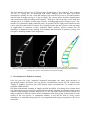
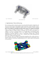
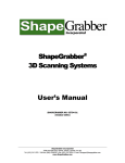
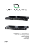
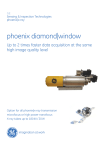
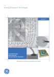
18th World Conference on Nondestructive Testing, 16-20 April 2012, Durban, South Africa
Fully-Automated 3D Metrology and Defect Analysis with High-Resolution
300 kV Microfocus Computed Tomography
Oliver Brunke1
1
Product Manager for 3D Metrology and Failure Analysis using Computer Tomography, GE Sensing &
Inspection Technologies GmbH, 31515 Wunstorf, Germany; Phone: +49 5031 172 142, E-mail:
[email protected], www.ge-mcs.com/phoenix
Abstract
With industrial X-ray computed tomography (CT), even low-contrast defects in cast parts, such as cracks, pores
and blowholes, can be localized and measured in three dimensions. Analysis of the defects can be performed
using either multi-positional 2D cross-section planes or the 3D volume view. Additionally, 3D metrology with
CT becomes more and more an effective tool for many tasks in production process monitoring such as the
manufacture of plastics, metal castings and precision components like injection nozzles. Particularly complex part
geometries with inaccessible or hidden features can be measured with CT in many cases faster than with
conventional Coordinate Measuring Machines (CMMs). This paper shows failure analysis and metrology tasks
automatically performed on a new GE CT system optimized for stable and reproducible CT scans and equipped
with a new unipolar 300 kV microfocus X-ray tube, new CT software for fully automated data acquisition,
volume processing and 3D evaluation capability.
Keywords: 3D Metrology, automated Computed Tomography, CT, µCT, CMM
1. Introduction
Complete 3D mapping means that CT can also be used for the non-destructive 3D
measurement of cast parts that cannot be inspected using conventional coordinate measuring
machines due to their complex internal geometry. Therefore, CT has numerous practical uses
in addition to non-destructive quality control; for instance, it can be used for optimizing and
reducing the time required for development and initial sampling processes, comparing
components with the target CAD model or reverse engineering in which 3D component data is
used to construct a three-dimensional CAD model (fig 1). Fully automated scanning and
analysis processes mean that the creation of first-article inspection reports, even for complex
components, is possible in less than one hour.
Fig. 1: Reverse engineering, automatic pore analysis and 3D metrology of a scanned automotive control arm
2. Advanced CT Technology
The new phoenix v|tome|x m of GE Inspection Technologies is the industry’s first compact
300 kV CT system for 3D metrology and failure analysis with less than 1µm detail
detectability, suitable for 500 x 600 mm samples with a field-of-view up to 300 mm diameter
and 400 mm in height and up to 50 kg in weight. The system offers excellent magnification
and resolution for high-absorbing metal samples. With up to 500 W the tube comes with also
enough power to examine a broad range of parts, including light metal castings in just a few
minutes. For particularly high-resolution scans, an optional 180 kV high-power nanofocus tube
can be selected at the touch of a button. Its versatility ensures the new system a wide spectrum
of applications in materials science, industrial failure analysis, process control and 3D
metrology in industrial sectors ranging from castings and electronics to plastics, geology and
aerospace, including turbine blade inspection.
Fig. 2: Comparison of a turbine blade scanned using a conventional 225 kV tube (left) and GE’s 300 kV (xy
sections): The 300 kV microfocus X-ray tube enables more precise scans with significantly reduced artifacts
ensuring more precise wall thickness measurements (right).
3. Non-Destructive 3D Defect Analysis
Over the past few years, industrial computed tomography has made great advances in
increasingly higher resolution and ever greater reconstruction speeds for 3D volume data.
Thanks to graphics processor unit (GPU)-based image reconstruction, CT results are now
available within minutes.
Full three-dimensional scanning of samples and the possibility of creating cross-sections from
any angle opens up new analysis-related and time-saving potential for foundry-based quality
controls. With automatic porosity analysis (fig. 3), the size of the inclusions can be shown on a
table or marked in different colours on the component itself, thus giving an indication as to the
quality of the cast process, or component stability. It can also be used to verify correct
assembly or to determine the position of cast components following an inconclusive 2D X-ray
inspection.
Fig. 3: Automatic porosity analysis of an automotive casting. The distribution of differently sized pores within the entire cast part can be
shown in different colours.
4. High-Resolution CT-Based 3D Metrology
Due to the large number of internal contours in cast parts made from plastic or light alloys, the
use of conventional measurement methods to inspect such parts is often not possible in a nondestructive way and takes a considerable amount of time. The fact that CT offers extremely
precise and complete 3D representation of objects opens up its field of application, meaning
that it is also suitable for coordinate measuring. This is because, in contrast to conventional
tactile or optical coordinate measuring systems, CT measuring systems are also able to
completely capture the hidden contours of specimens, such as cavities and undercuts. In
addition, a CT scan of a specimen results in a very high number of measurement points,
typically in the order of magnitude of 105 to 106, which can then be used (through the
application of statistical methods) to achieve a measurement resolution that is typically
significantly below 1/10 of the voxel size (voxel = volumetric pixel); which, depending on the
object size, is within the micrometer range.
Fig. 4 shows, by way of an example, a target/actual comparison of the variances between a
specimen and the CAD model. The swiftly generated results from these measurements can be
used as a basis for correcting the manufacturing process in a timely manner and optimizing
series production.
Fig. 4: Using false colour image display to compare the measurement data and CAD model allows a qualitative
judgment to be made quickly regarding the production quality of the casting.
The precision of the measured raw data (CT projection data) determines the accuracy of all
subsequent evaluations. In addition to a stable system structure that is optimized for the
specific application at hand, data processing is the key to successful CT-based measurement.
For optimal measurement results, therefore, the reconstruction algorithm used to calculate the
volume data has to take into account and correct the unavoidable physical effects of CT
scanning, such as 'beam hardening'. The phoenix|x-ray CT product range of GE Inspection
Technologies features a variety of software modules for optimized volume data reconstruction.
It also offers a comprehensive range of software packages for surface-data analysis, including
element modelling, DIN/ISO-compliant geometric dimensioning and tolerancing calculation
(GD&T), and even the fully-automated generation of initial sample inspection reports. The
measurement data generated using dedicated, optimized surface extraction is traced back to
normal standards using DKD-certified (German metrology accreditation body) specimens.
5. The CT-based 3D measurement process chain:
5.1 Data acquisition
The actual physical measurement is taken by scanning a series of 2D X-ray projection images.
To do this, the specimen is positioned on a granite-based precision manipulation system and,
during the measurement, is completely rotated through 360° on a precision turntable. A 2D
projection image is typically taken every <0.5°. The quality of the raw data, and naturally the
accuracy of all subsequent evaluations, is significantly influenced by the sharpness of the X-ray
images, which is heavily dependent on the quality of the x-ray source and detector in addition to
the precision and stability of the manipulation device. Therefore, the more effectively the CT
measurement system performs this first step, the more precisely the measurement task can be
performed.
5.2 Volume reconstruction
The volumetric data set for the specimen is generated from the raw data using a numeric
reconstruction method filtered back-projection. For optimum measurement results, the
reconstruction algorithm should take into account and correct the physical effects, such as beam
hardening or thermal expansion, during the raw data capture in step 1.
5.3 Surface data generation
For the subsequent processing of the measurement results, the surface is extracted from the
volume data as a generic ASCII point cloud or STL surface for import into 3D inspection
software, such as the Polyworks Inspector™ (InnovMetric Software Inc., Canada).
5.4 Evaluation and analysis (virtual coordinate measuring machine)
After importing the surface data from the specimen into the 3D analysis software, the additional
measuring steps can be performed (fig. 5). These steps include a target/actual comparison
between the surface data and the CAD model with a variance analysis or measurements using
ruled geometries.
Fig. 5: Nom. /act. comparison and evaluation of three dimensional parameters on a scanned cylinder head.
6. Fully Automated Data Acquisition and Volume Processing
With GE’s advanced phoenix datos|x CT software, the entire CT chain described above can be
fully automated. The software offers fully automated data acquisition and volume processing,
so that high resolution, precision metrology and failure analysis tasks can now be performed
with minimal operator training within a dramatically reduced required operator time. The click
& measure|CT functionality minimizes the operator time and influence, while highly
increasing the repeatability and reproducibility of CT results. Once the appropriate setup for a
part is programmed, the whole scan and reconstruction process as well as 3D failure analysis
or 3D metrology evaluations like generation of first article inspection reports can be executed
automatically.
The click & measure|CT functionality of the new software allows users to display and analyze
the 3D results on the screen in just three steps: fix the work piece, start the scan, check the
results. Therefore, the skill requirements for the operator are dramatically reduced, while the
required operator time to run a CT analysis is decreased by a factor up to 5 compared to the
previous software version. This saves costs and highly increases the repeatability and
reproducibility of CT results by minimizing the operator influence. Once the appropriate setup
is programmed, the whole scan and reconstruction process including volume optimization
features or surface extraction runs without any operator interaction. Furthermore, 3D failure
analysis or metrology tasks performed with third party programs can be executed
automatically. Since the entire process of the CT data acquisition over the volume
reconstruction to implementation of the measurement runs completely automatically, it is now
possible to conduct the first article inspection of a complex component in less than 60 minutes.
7. Substantiation of CT Measurement Accuracy
To substantiate the measurement accuracy of the phoenix|x-ray computed tomographs of GE
Measurement & Control, and therefore their suitability for use as 3D coordinate measuring
machines, a valve block made from aircraft aluminium with an edge length of 130 mm was
subjected to a CT scan at Continental AG in Frankfurt followed by a reference measurement
using high-precision tactile 3D coordinate measurement technology. GE’s phoenix v|tome|x
computed tomograph was used for the CT scan and a Hexagon Metrology Leitz 3D PMM
8.6.6 coordinate measuring machine for the reference measurement.
Table 1 contains extracts from the specimen inspection report and demonstrates the excellent
concordance between both the KMM and CT measurement methods: The proven diameter and
length variance is ≤6 µm.
Parameter
Target CAD
Tolerance
Actual CT
Actual CMM
CT/CMM variance
Ø Z 1 [mm]
28.000
0.050
28.035
28.034
0.001
Distance A 1 [mm]
70.500
0.100
70.442
70.447
-0.005
Table 1: Excellent correspondence between the measurement data from the 3D coordinate measuring machine
and high-resolution computed tomography
8. Conclusion: How Advances in CT Systems are Benefiting Foundries
A new tomograph from the GE’s phoenix|x-ray business which has recently been placed on the
market and which features a revolutionary unipolar 300 kV/500 W microfocus x-ray tube is
enabling CT analyses of difficult-to-penetrate components at particularly high levels of
magnification (fig. 5). It is the first time that a resolution of up to 1 µm has been achieved with
a 300 kV X-ray tube. The CT system also uses a new high dynamic temperature-stabilized
digital detector with even higher contrast resolution. As a result of recent hardware and
software developments, the phoenix v|tome|x m (fig. 6) offers effective CT results in a very
short time.
The user-friendly and highly efficient phoenix|x-ray CT software datos|x 2.0 includes a wide
variety of modules for optimizing CT results for superior precision and quality. Additionally,
the new bhc|module corrects beam hardening automatically. This compensation for
undesirable artifacts significantly increases the precision of pore analyses or surface extraction
for subsequent dimensional measurements. The click & measure|CT functionality offers a
significant reduction of the required operator time. Hardware innovations are also ensuring
more precise measurement results.
The phoenix v|tome|x m can be used for full, high-resolution 3D scanning of samples, making
it ideal for non-destructive quality control in foundries. The system also has a special
metrology package that contains everything needed for precise and intuitive 3D metrology,
from calibration instruments to a high accuracy direct measuring system. In many cases, Ct
offers considerable advantages compared to conventional coordinate measuring machines,
especially, when measuring complex parts or hidden or difficult-to-access surfaces, such as
high density of measurement points and fast capturing even of the complete internal geometry
of the work piece. Fully automated click & measure|CT allows the entire CT process to be
fully automated minimizing the operator time and influence while highly increasing the
repeatability and reproducibility of the CT results.
Fig. 6: Due to its unipolar microfocus X-ray tube, the phoenix|x-ray v|tome|x m CT system is particularly suited
to high-resolution scans of highly radiation-absorbent components at particularly high levels of magnification.