1
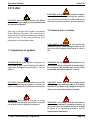
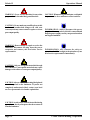
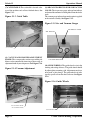
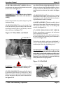
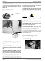
POLARIS II LAMINATOR
OPERATOR MANUAL
Part Number: 930-115 REV: - REV Date: 7-27-04
© 2004 GENERAL BINDING CORPORATION. ALL RIGHTS RESERVED.
Do not duplicate without written permission.
The information in this publication is provided for reference and is believed
to be accurate and complete. General Binding Corporation is not liable for errors
in this publication or for incidental or consequential damage in connection with
the furnishing or use of the information in this publication, including, but not
limited to, any implied warranty of fitness or merchantability for any particular use.
General Binding Corporation reserves the right to make changes to this
publication and to the products described in it without notice. All specifications
and information concerning products are subject to change without notice.
Reference in this publication to information or products protected by
copyright or patent does not convey any license under the rights of General
Binding Corporation or others. General Binding Corporation assumes no liability
arising from infringements of patents or any other rights of third parties.
This publication is copyrighted © 2004 by General Binding Corporation. All
rights reserved. The information contained in this publication is proprietary and
may not be reproduced, stored, transmitted, or transferred, in whole or in part, in
any form without the prior and express written permission of General Binding
Corporation.
Operations Manual
Polaris II
Table of contents
1.0 Safety
1.1 Explanation of symbols
1.2 General rules of safety
1.3 Labels
Figure 1.3.1 Safety label placement
1-1
1-1
1-3
1-5
2.0 Warranty
2.0 Warranty
2.1
3.0 Specifications
3.1 Film and sheet size
3.2 Functions
3.3 Weight
3.4 Dimensions
3.5 Electrical requirements
3.6 Recomended work space
Figure 3.4.1 Dimensions
3-1
3-1
3-1
3-1
3-1
3-1
3-2
4.0 Installation
4.1 Pre-installation
4.2 Setting up your laminator
Figure 4.2.1 Paper Guide
4-1
4-2
4-2
5.0 Operations
5.1 Components on the laminator
Figure 5.1.1 Power Switch
Figure 5.1.2 Feed Table Details
Figure 5.1.3 Catch Table
Figure 5.1.4 Vacuum Adjustment
Figure 5.1.5 Air and Vacuum Gauges
Figure 5.1.6 Guide Wheels
Figure 5.1.7 Heat Roller and Shield
Figure 5.1.8 Pull Roll
Figure 5.1.9 Paper Pin
Figure 5.1.10 Film Support Arm
5.2 Control panel
Figure 5.2.1 Control panel
5.3 Operator screens
5.4 Supply shaft
5.5 Separator knife
5.6 Film alignment
5.7 Film Tension
Figure 5.7.1 Manual Tension Knob
© 2004 General Binding Corporation
5-1
5-1
5-1
5-2
5-2
5-2
5-2
5-3
5-3
5-4
5-4
5-5
5-6
5-7
5-9
5-9
5-9
5-9
5-10
Page I
Polaris II
Operations Manual
6.0 Applications
6.1 Film loading and threading
Figure 6.1.1 Suction Cup Control
Figure 6.1.2 Suction Cups and Paper Stack
Figure 6.1.3 Film Leader
6.2 Helpful hints
6.3 Important points to remember
Quick Set up
Application Guide
6-1
6-1
6-1
6-2
6-3
6-3
6-5
6-6
7.0 Maintenance and Troubleshooting
7.1 Cabinets and cover
7.2 Clean the rollers
7.3 Misc Maintenance
7.4 Troubleshooting
Figure 7.3.1 Troubleshooting guide
Page II
7-1
7-1
7-2
7-2
7-3
© 2004 General Binding Corporation
Operations Manual
Polaris II
1.0 Safety
CAUTION: Do not attempt to operate your Polaris
Laminator until you completely read and understand
this Operations Manual.
Your safety, as well as the safety of others, is important to
General Binding Corporation. This section contains
important safety information which must be adhered to
while operating, cleaning and performing basic
maintenance in and around the machine.
ELECTRICAL HAZARD: [This symbol is used prior
to a step. The information following this symbol is
to prevent an electrical shock condition that may be
caused by an operators action or machine function.]
1.2 General rules of safety
1.1 Explanation of symbols
ELECTRICAL HAZARD: Do not operate the
laminator if power cord is damaged or frayed. You
can be severely shocked, electrocuted or cause a
fire.
INFORMATION: [This symbol is used prior to,
during and/ or after a step. Following this symbol is
important information pertaining to current
subject.]
WARNING: Do not operate this laminator if you
are not physically, psychologically or emotionally fit.
Do not operate this machine until you have been
trained and read this manual in it’s entirety.
CAUTION: [This symbol is used prior to a step. The
information following this symbol is to inform you
of how to avoid harm to you and others around you}
WARNING: Do not wear ties, loose fitting clothes
or dangling jewelry while operating or servicing the
laminator. These items can get caught in the nip and
choke you or you can be crushed or burned.
WARNING: [This symbol is used prior to a step.
The information following this symbol is to inform
you of how to avoid a dangerous situation.]
© 2004 General Binding Corporation
WARNING: Never tamper with the safety devices
to increase the laminator’s production capacity. In
the event a safety device should fail, never attempt
to bypass it for operation. Consult a service
representative immediately.
Page 1-1
Polaris II
WARNING: Never use this machine for any other
purpose than its intended design and function.
CAUTION: Do not make any modifications to this
laminator. Unauthorized changes will void your
warranty and may cause extensive repairs or create
poor output quality.
WARNING: Do not attempt to repair or service the
laminator. Disconnect the plug from the power
receptacle and contact your local sales/ service
representative.
Operations Manual
CAUTION: When moving the laminator, avoid quick
stops, excessive force and uneven floor surfaces.
INFORMATION: Always disconnect the power
plug from the receptacle to which it is connected and
keep the power supply cord in your possession when
moving the laminator.
INFORMATION: Any concerns for safety or
operation should be brought to the attention of your
local service representative immediately.
CAUTION: Only use acceptable materials through
this laminator. Unacceptable materials may cause
damage to the rollers or cause poor output quality.
CAUTION: Always observe all warning labels placed
at various points on the laminator. If you do not
completely understand a label, contact your local
service representative for further explanation.
CAUTION: Avoid contact with the heat roller during
operation or shortly after power has been removed
from the laminator.
Page 1-2
© 2004 General Binding Corporation
Operations Manual
1.3 Labels
Safety warning labels are placed at various locations on
the laminator. Do not remove any of these labels. They
are placed for your safety as well as the safety of those
working around you.
Below are illustrations of the safety labels and a description
of their meanings.
Polaris II
This label is located on the rear panel in the center of the
laminator just below the film supply shaft between the pull
rollers and decurling bar.
- The safety label below means that you should always
replace a fuse with the same size and type of fuse. This
will reduce the risk of fire.
Hot rollers
– The safety labels below mean that you could be burned
and your fingers and hands could be trapped and crushed
in the rollers. Jewelry and long hair could be caught in the
rollers and you could be pulled into them.
This label is located on the side cover near the fuse panel
located on the rear of the machine.
Pinch point
– The safety label below means use extreme caution when
placing your hands in the proximity of the pull rollers nip.
You should never place your fingers or other items in this
area while the machine is running.
One of each label is placed on each side from the front
operating position just in front of the heat rollers nip.
Electrical hazard
This label is located between the pull rollers and the
decurling bar center of the rollers.
– The safety label below means that you could be seriously
hurt or killed if you open the product and expose yourself
to hazardous voltage.
© 2004 General Binding Corporation
Page 1-3
Polaris II
Operations Manual
– The safety label below means that you could be seriously
injured if you come in contact with the moving chain and
sprockets of the drive system.
This label is located near all drive sprockets on the machine.
Sharp knife
– The safety label below means that you could cut yourself
if you are not careful.
This label is located on the rear panel in the center of the
laminator just above the Electrical hazard safety label and
below the rear slitter.
Refer to Figure 1.3.1 Safety label placement for
illustration.
Page 1-4
© 2004 General Binding Corporation
Operations Manual
Polaris II
Figure 1.3.1 Safety label placement
(2) O ne on each side of the lam inator
(1) B etween pull rollers and decurling bar
(1) C enter rear panel below film unwind.
N ear all sprockets
Located near Fuse Holder
(2) O ne on each side of the lam inator
© 2004 General Binding Corporation
Page 1-5
Polaris II
Page 1-6
Operations Manual
© 2004 General Binding Corporation
Operations Manual
PolarisII
2.0 Warranty
GBC warrants to the original purchaser for a period of
ninety days after installation that this laminator is free
from defects in workmanship and material under normal
use and service. GBC’s obligation under this limited
warranty is limited to replacement or repair, at GBC’s
option, of any part found defective by GBC without charge
for material or labor.
THIS LIMITED WARRANTY IS IN LIEU OF ALL OTHER
WARRANTIES EXPRESSED OR IMPLIED.
WARRANTIES OF MERCHANTABILITY OR FITNESS
FOR A PARTICULAR PURPOSE ARE EXPRESSLY
EXCLUDED. ANY REPRESENTATIONS OR PROMISES
INCONSISTENT WITH, OR IN ADDITION TO, THIS
LIMITED WARRANTY ARE UNAUTHORIZED AND
SHALL NOT BE BINDING UPON GBC. IN NO EVENT
SHALL GBC BE LIABLE FOR ANY SPECIAL,
INCIDENTAL, OR CONSEQUENTIAL DAMAGES,
WHETHER OR NOT FORESEEABLE.
This limited warranty shall be void if the laminator
has been misused; mishandled; damaged by
negligence, by accident, during shipment, or due
to exposure to extreme conditions; repaired,
altered, moved, or installed by anyone other than
GBC or its authorized agents; or if incompatible
film was used. GBC’s obligation under this limited
warranty does not include routine maintenance,
cleaning, adjustment, normal cosmetic or
mechanical wear, nor freight charges.
Without limiting the generality of the previous
paragraph, GBC’s obligation under this limited
warranty does not include:
1.
Damage to the rollers caused by knives,
razors, or other sharp tools; by any foreign
objects falling into the working area of the
laminator; or by cleaning the laminator with
solutions or materials that harm its surfaces;
2.
Damage caused by adhesives; nor
3.
Damage caused by lifting, tilting or attempting
to position the laminator other than rolling it
on its castors across even surfaces.
For European Union Residents Only: This guarantee
does not affect the legal rights which consumers have
under applicable national legislation governing the
sale of consumer goods.
© 2004 General Binding Corporation
Page 2-1
Polaris II
Operations Manual
This page intentionally left blank.
Page 2-2
© 2004 General Binding Corporation
Operations Manual
Polaris II
3.0 Specifications
3.4 Dimensions (W x H x D)
Refer to Figures 3.4.1 Dimensions.
This section provides specific information regarding the
laminator. Any specification not provided must be
requested from GBC.
Machine
– 50.5 in. x 54 in. x 85 in.
– (128.25 cm. x 137 cm. x 216 cm)
– 105” long with delivery table
3.5 Electrical requirements
3.1 Film and sheet size
Film
– Single side films
(ie., GBC LAYFLAT, GBC HI-TAC)
Core
– 3 in. (7.6 cm)
Sheet Size
– Min. 11.0 in. x 8.5 in. (28x 20 cm)
– Max. 25 in. x 25 in. (64 x 64 cm)
Sheet Weight – Min. 24 lb. bond
– Max. 10 pt. board
Pile Height
– 17 in. (44 cm)
INFORMATION: Refer to the serial plate located
on the rear of the laminator for specific electrical
ratings applicable to the unit.
Voltage
Current
Power
Wall Receptacle
– 230VAC ~ 60Hz
– 42A (50 AmpCircuit Breaker)
– 9660 W
– NEMA 6-50R
Main Roll Diameter- 10.0 inches (24 cm)
3.6 Recomended Work Area
3.2 Functions
The Polaris should have a working area of 12 ft X 16 ft
for ease of opperation and safety purposes.
Speed
< up to 50 ft./ min (6 m/ min.)
Temperature – 7 Settings
225, 240, 250, 260, 270,
280, 290 deg. F
3.3 Weight
Unpacked
– 1870 lbs. (850 kilograms)
Shipping Weight
– 2156 lbs. (980 kilograms)
© 2004 General Binding Corporation
Page 3-1
Polaris II
Operations Manual
Figure 3.4.1 Dimensions
5 4 in c h e s
1 0 5 in c h e s
Page 3-2
5 0 .5 in c h e s
© 2004 General Binding Corporation
Operations Manual
Polaris II
4.0 Installation
GBC Films Group is committed to a program of ongoing
product improvement. As a result, we are providing these
instructions so you can insure that your new Polaris
Laminator is properly and securely unpacked, moved,
and installed.
CAUTION: Too high or too low of an operating
position can lead to serious bodily injury and/ or
cause poor output quality.
1. All support feet should be positioned completely on
the supporting surface.
Before the Polaris Laminator can be installed, there are a
few requirements that must be met. Make certain that
each of the requirements listed in the following preinstallation checklist are met before beginning installation.
CAUTION: The laminator is a heavy piece of
equipment and may cause injury and/ or require
extensive repair work if it falls.
4.1 Pre-installation
The supporting surface may also be strong enough to hold
the material being laminated.
Are doorways and hallways wide enough for the
laminator to be moved to the installation site?
2. The supporting surface should be large enough to
Is there ample room for the laminator?
support the feed table and catch table comfortably.
A work area must be established that allows for
operation in both the front and rear of the
laminator and provides space for efficient material
flow.
3. Avoid locating the laminator near sources of heat or
cold. Avoid positioning the laminator in the direct path of
forced heated or cooling air.
Is the environment appropriate for the laminator?
The laminator requires a clean, dust and vapor
free environment to operate properly. It must not
be located where there is air blowing directly on
the machine.
Have you contacted a certified electrician to both
wire the laminator and ensure that adequate power
is being supplied, having the appropriate capacity,
over current protection and safety lockouts are
available?
© 2004 General Binding Corporation
INFORMATION: This effects the performance of
the heating system and could result in poor output
quality.
Page 4-1
Polaris II
4.2 Setting up your laminator
Operations Manual
Figure 4.2.1 Paper Guide
P A P E R G U ID E
After placing your Polaris laminator, the catch table must
be installed.
1. To assist in the installation of the catch table, a set of
tools has been provided. The tools are sent with the
machine and can be found wrapped up on the front feed
table.
2. Locate rear feed table and inspect for any damages
that may have been caused during shipping. Locate Four
bolts, two C-clamps, two flat mounting plates, two legs,
and four nuts.
3. Place the table leg between the C-clamp and the flat
mounting plate. Secure the legs to the table using bolts
and nuts. NOTE: These legs may have been preassembled at the factory.
CATC H TABLE
Once the catch table is in place, connect the air/ vaccum
pump (rated 230V@ 10 Amps or less) to the receptacle
located under the separator. The receptacal is identified
by the label shown below.
Refer to Section 3.5 Electrical requirements
4. At this time the feed table legs can be adjusted to
desired height (approx 16”). Table height (angle) depends
on the paper stock being laminated. Tighten nuts.
5. After the feed table is set to desired height, mount the
table on the machine using the front table hooks. To apply
the rear catch table, first locate the catch table support
bar located at the rear of the machine. The catch table
hooks directly to the catch table support bar
6. At this time the paper guides can be mounted onto the
catch table. See Figure 4.2.1.
Page 4-2
© 2004 General Binding Corporation
Operations Manual
Polaris II
5.0 Operation
This section covers the components of the laminator, the
control panel, feed table, supply shaft, knife assembly film
alignment and tension knobs.
5.1 Components on the laminator
(1) POWER ON/ OFF: This is located to the lower right
of the catch table. When set to the “I” position, applies
power to the laminator. When set to the “O” position,
removes power from the laminator. See Figure 5.1.1.
Figure 5.1.1 Power Switch
(3) TABLE SIDE GUIDE: The side guides are
adjustable to ensure accurate feeding. The Polaris is left
justified All settings should be set from left to right. See
Figure 5.1.2.
CAUTION: The feed guide should be set outside
the width of the film. The film should be completely
inside the sheet being fed.
(4) SUCTION CUPS: The Feed Table works with a
series of suction cups. The suction cup bar can be adjusted
to allow operator to increase or decrease suction. See
Figure 5.1.2.
(5) PILE BLOWER: There are a series of air blow holes
located on a support bar for the infeed plate, which blows
air into the sheet pile. This helps in the separation of sheets
and allows one sheet to be fed into the machine at a time.
See Figure 5.1.2.
(6) PILE HEIGHT SENSORS: The Pile Height Sensors
control the feed table by automatically raising the table as
images are being fed into the laminator. This is adjusted
by the operator while the machine is running. See Figure
5.1.2.
Figure 5.1.2 Feed Table Details
P IL E H E IG H T S E N S O R
T A B L E S ID E G U ID E
POWER SWITCH
(2) FEEDER : The feeder is completely automatic in
operation. After set up, minor pile height adjustments will
be necesary for changes in pile characteristics.
INFORMATION: The feed table will only allow one
sheet to enter the machine at a time. The Polaris
will accommodate an 17 inch pile height.
© 2004 General Binding Corporation
S U C T IO N C U P S
P IL E B L O W E R
Page 5-1
Polaris II
(7) CATCH TABLE: The catch table is located at the
rear of the machine and collects finished sheets. See
Figure 5.1.3.
Figure 5.1.3 Catch Table
Operations Manual
(9) AIR GAUGE & REGULATOR AND VACUUM
GAUGE: The air pressure gauge and regulator indicate
and control the amount of air being blown into the feeder
stack.
The vacuum gauge indicates how much suction is applied
to the suction assembly. See Figure 5.1.5.
Figure 5.1.5 Air and Vacuum Gauges
A IR R E G U L A T O R
A IR G A U G E
C A TC H TAB LE
(8) VACUUM AND BLOWER ADJUSTMENT
KNOBS: The vacuum to the suction cups and the pile
blower can be controlled by increasing or decreasing air
adjustment knob of your compressor. See Fuigure 5.1.4.
Figure 5.1.4 Vacuum Adjustment
VACUUM GAUGE
(10) GUIDE WHEELS: The guide wheels assist in the
entering and exiting of sheets. The guide wheels should
be adjusted prior to running a job. Adjustments may have
to be made as jobs change. The guide wheels are to be
equally spaced to fit on the sheet to be run. See Figure
5.1.6.
Figure 5.1.6 Guide Wheels
VACUUM AND BLO W ER
A D JU S T M E N T K N O B S
G U ID E W H E E L S
Page 5-2
© 2004 General Binding Corporation
Operations Manual
Polaris II
(11) HEAT ROLLER SAFETY SHIELD: Reduces
entanglement, entrapment and inadvertent contact with
the heat rollers. See Figure 5.1.7.
(14) FILM TENSION IDLER ROLLER: Located
to the rear and next to the Teflon Heated Roller, it directs
the film around to the Teflon Roller and has a brake to
apply film tension to eliminate film wrinkles. See Figure
5.1.8.
INFORMATION: The Heat Roller Safety Shield is
designed to cover the heat roller while machine is
running.
(15) DECURLING BAR: The decurling bar is located
in the middle of the machine, just past the main rolls. The
decurling bar can be adjusted with the decurling bar
adjustment knob to ensure a flat output.
To move the main roller safety shield, simply tilt up. The
laminator will stop.
(12) HEAT ROLLER: Teflon coated steel tube. Used
to heat the laminating film and compress the film to the
items being laminated. Heat is provided by 3 internal
infrared elements. See Figure 5.1.7.
Figure 5.1.7 Heat Roller and Shield
H E AT R O L L E R S AF E T Y
S H IE L D (O P E N )
(16) KNIFE ASSEMBLY: The knife assembly is located
in the back of the machine. The knife automatically cuts
and separates the sheets as they are run through the
machine. See Figure 5.1.8.
(17) KNIFE SEPARATOR SAFETY SHIELD:
Reduces entanglement, entrapment and inadvertent
contact with the separator knife.
To raise the knife separator safety shield, gently lift. Once
the safety latch has been retracted, power to the motor is
removed. See Figure 5.1.8.
To close the safety shield, gently lower the shield until it
is in it’s closed position. The motor will revert to its
condition prior to the safety shield being raised.
H E AT R O L L E R
INFORMATION: The laminator will operate only
when the knife separator, pull roll, decurling bar, film
tension idler bar and feeder shields are in their closed
position and the safety interlock latch is properly
engaged. Power to the motor is removed when any
safety shield is in the open position.
Figure 5.1.8 Pull Roll
K N IF E S E P A R A T O R
F IL M
S A F E T Y S H IE L D
WARNING: Avoid contact with the heat roller.
Direct contact with the heat roller can burn you.
(13) PULL ROLLERS: The bottom pull roller, located
in the middle of the laminator, is motor driven. When
Rollers are in the down position, they simultaneously pull
the film and improve the quality of the laminated item.
See Figure 5.1.8.
T E N S IO N
ID L E R
(O P E N )
K N IF E
R O L L
P U L L R O L L S
A S S E M B L Y
© 2004 General Binding Corporation
Page 5-3
Polaris II
Operations Manual
(18) PAPER GUIDE PIN: The paper guide pin allows
the operator to raise the finish product up to the knife
separator for a smooth feed into the knife separator. See
Figure 5.1.9.
by the yellow hazard stickers and should be used to stop
the machine in the event of an emergency. The emergency
stop removes power from the machine.
(23) NIP POINT: The point at which two rollers come
into contact. The nip point of the heat rollers is the place
at which the items for lamination are introduced into the
laminator.
Figure 5.1.9 Paper Pin
P A P E R P IN
CAUTION: Only feed acceptable materials through
the nip of the rollers. Unacceptable materials may
create unsafe conditions.
(24) FILM WEB: Laminating film loaded into the machine
(25) CONTROL PANEL: The control panel is located
on the top, control side of the machine.
(26) FILM SUPPORT ARM: Arm used to support
the drive side of the air shaft. See Figure 5.1.10.
(27) SUPPORT LOCKING PIN KNOB: Locateded
on film support arm. Turn knob to lock air shaft to support
arm. See Figure 5.1.10.
P A P E R P IN K N O B
Figure 5.1.10 Film Support Arm
S U P P O R T L O C K IN G
P IN K N O B
(19) SUPPLY SHAFT: The supply shaft holds the film
supply and the core adapters hold the rolls of film on the
film shaft.
(20) CORE ADAPTERS: The film shaft holds the supply
roll while the core adapters hold the rolls of film on the
shaft.
F IL M S U P P O R T
A R M
(21) FILM TENSION CONTROL: Allows the
operator to increase or decrease film web tension as
necessary to reduce curl and wrinkles. Refer to Section
5.2 Film Tension for more information on tension.
(22) EMERGENCY STOPS: The emergency stops
are located on top of the laminator. They can be located
Page 5-4
© 2004 General Binding Corporation
Operations Manual
Polaris II
5.2 Control panel
Refer to Figure 5.2.1 Control panel
(1) START/SPEED UP: This button has a dual function.
When the machine is stopped and all safety covers are
closed, press and hold the START button to begin
operation. The feeder head will cycle home while the
START button is pressed. Once the feeder head is home,
press the START button for 1 second. The nip roller will
start to raise and after about 2 seconds, the laminator will
start.
Once the laminator is running, pressing the START button
again will increase the running speed by 3 ft/min.
(2) STOP: Pressing the STOP button while the laminator
is running will stop the laminator. Pressing the STOP button
a second time (when machine is stopped) will lower the
nip roller. Be sure to lower the nip roller when the job is
complete.
(3) DECREASE SPEED: If the laminator is running,
pressing this button decreases the speed by 3 ft/min.
(4) BLADE RETURN/INCH: This is a three position
switch with two functions. When the switch is in the vertical
position, the machine runs normally. Turning the switch to
the right (clockwise) and holding will inch the laminator
roll forward at 3 ft/min. Turning the switch to the left
(counter clockwise) will send the knife to the home position
if all covers are closed.
(5) BRAKE PRESSURE ADJUSTMENT: This dial
is used to adjust the pressure on the film brake. Turning
the dial to the left (counter clockwise) decreases the film
tension. Turning the dial to the right (clockwise) increases
the fime tension.
(6) TOUCH SCREEN: The Touch screen has five
operator screens. To navagate through the screens, use
the left and right arrow keys displayed on the bottom of
each screen. Hitting the arrow keys continuously will wrap
the screens around to the beginning. The “Speed” screen
is considered the base screen.
Refer to 5.3 Operator Screens for a description of
each screen.
© 2004 General Binding Corporation
Page 5-5
Polaris II
Operations Manual
Figure 5.2.1 Control panel
6
1
2
4
Page 5-6
3
5
© 2004 General Binding Corporation
Operations Manual
Polaris II
(6) R: Reset Counter. This button resets the current job
counter to 0.
5.3 Operator Screens
The Touch screen has five operator screens. The following
is a description of each screen:
SPEED SCREEN
1
3
(8) SCREEN NAVIGATION: The arrow buttons move
from one screen to the next. These buttons work the same
on all of the operator screens.
4
2
0 SPEED
0 COUNT
7
OVER
LAP
+
<---
T
C
R
M
--->
(7) OVER LAP +/-: Pressing the “+” button increases
the over lap between sheets while pressing the “-” button
decreases the over lap.
5
6
MISC SERVICE SCREEN
3
1
8
(1) SPEED: Displays current speed of machine in ft/min.
(2) COUNT: Displays the current job count. The counter
increaments every time the knife makes a pass over the
conveyor while the laminator is running. To reset the
counter, press the “R” button on this screen.
(3) T: This is a display tool only. When the symbol turns
to a black background with a white “T”, the temperature
of the lamination roll had reached the set point and
laminator is ready to run.
(4) C: This is a display tool only. The symbol turns to a
black background with a white “C”, when all of the safety
covers are closed.
(5) M: Misfeed override. When setting up the feeder, the
operator may want to override the misfeed sensor. Pressing
this button will override the alarm and allow the machine
to run while allowing gaps between the sheets. When the
button is black with a white “M”, the misfeed sensor is
active and will stop the machine when gaps between the
sheets are larger than 1/4”. When the button is white with
a black “M”, the misfeed sensor is overridden. It is not
recommended to laminate while the misfeed sensor is
overridden because film may stick to the nip roll and cause
a wrap up.
© 2004 General Binding Corporation
COMP
OFF
<---
SERV
2
KNIFE
ON
--->
(1) COMP OFF/COMP ON: This button toggles the
compressor on and off.
(2) KNIFE ON/KNIFE OFF: This activates the knife
to cut when the over lap sensor is covered. Turning the
knife off prevents the knife from activating when the over
lap sensor is covered.
(3) SERV: These buttons are reserved for GBC Service
Technicians.
Page 5-7
Polaris II
Operations Manual
TEMPERATURE SCREEN
1
2
TE M P E R A TU R E
TO P
ON
O N /O FF
BOT
OFF
<---
--->
(2) PAPER WEIGHT: Use these buttons to select the
nip pressure for the machine.Almost all paper stock can
be run at HIGH pressure. If you experience wrinkles in
the paper, stop the machine and select a lower pressure.
You can not adjust the nip pressure while the machine is
running.
PILE TABLE SCREEN
1
2
P ILE T A B L E
(1) TOP ON/OFF: This button toggles the heater for the
top roll on and off. Be sure to go to the PAPER AND
FILM screen and select the correct film type for the job
running. The symbol to the left of the button indicates when
the heater coils are pulsing on (black) and off (white).
(2) BOT ON/OFF: This button toggles the heater for the
bottom roll on and off. This heater will only be active
when the film type of “HiTac” is selected on the PAPER
AND FILM screen. The symbol to the right of the button
indicates when the heater coils are pulsing on (black) and
off (white)
PAPER AND FILM
OPP
PET
HiTac
LOW
MED
HIGH
2
<---
<---
P IL E
DN
--->
(1) PILE UP: Continually pressing the PILE UP button
brings the paper pile up. This button is only active when
the laminator is stopped. The table will automatically stop
when you release the button, the pile up sensor is activated,
or the top limit switch is activated.
(2) PILE DN: Pressing and releasing the PILE DN button
will send the pile down until the PILE DN button is pressed
again or the pile down limit switch is activated. The
operator can also stop the pile down by placing their hand
under the pile height sensor for 1 second.
PAPER AND FILM SCREEN
1
P IL E
UP
--->
ALARM SCREENS
There are a number of alarm screens that appear if there
is a problem with the laminator. The following is a list of
these screens:
MISFEED - This alarm is indicated when the misfeed
sensor is activated and the laminator will stop. Press
ACCEPT to acknowledge the alarm.
(1) FILM TYPE: Use these buttons to select the film
type that is loaded. This is important in that this is what
sets the temerature set point for the lamination roll.
Page 5-8
KNIFE JAM - When the knife does not travel from
home to the return sensor within 3 seconds, the knife jam
© 2004 General Binding Corporation
Operations Manual
alarm will activate and the laminator will stop.
TOP HEAT SENSOR BLOCKED - When the top
heat sensor is blocked for more than 5 seconds, this alarm
will activate. When the alarm is displayed, the heat
automatically shuts off and must be manually reset.
BOTTOM HEAT SENSOR BLOCKED - When the
bottom heat sensor is blocked for more than 5 seconds,
this alarm will activate. When the alarm is displayed, the
heat automatically shuts off and must be manually reset.
COVER ALARMS - There are 5 cover alarms. Feeder
Cover, Laminator Cover, Draw Cover, Cutter Cover and
Tension Roller. When the start button is pressed with a
cover open, this alarm will activate. The operator can
either accept the alarm or close the cover.
Polaris II
4. Screw in the Support Locking Pin Knob until the locking
pin is secured into the film supply shaft.
5. Spin roll to insure smooth rotation.
5.5 Separator Knife:
The integrated sheet separator is able to run with continuous
web flow for high production output. The precision knife
separates sheets while lamination web is moving.
E-STOP ALARM - When the start button is pressed
with an E-STOP button activated, this alarm will display.
Reset the E-STOP to continue operation.
INFORMATION: The laminator will operate only
when the knife separator, pull roll, decurling bar, film
tension roller and feeder shields are in their closed
position and the safety interlock latch is properly
engaged. Power to the motor is removed when any
safety shield is in the open position.
5.4 Supply Shaft
5.6 Film Alignment
To remove film
1.. Release any tension from the supply shaft.
The Polaris laminator is a left justified machine. Film should
be aligned from the left going to the right. Film should not
be centered on the supply shaft.
2. Unscrew the Support Locking Pin Knob until the Film
Supply Shaft is free.
5.7 Film Tension
3. Gently lower the film support arm.
4. Loosen and remove core chuck end.
5. Remove film at this time.
To replace
1. Slide the film over the supply shaft adhesive side away
from the roller.
On the Operator Control Panel, use the Film Tension Knob
to adjust the amount of brake tension applied to the Film
Idler Roller. Clockwise will increase the brake. Counterclockwise will decrease the brake. Refer to Section 5.2
Control Panel for information on setting the film tension.
If the Film Idler Roller is not providing enough film tension,
additional tension can be set using the manual tension knob
on the supply shaft. See Figure 5.7.1.
2.Tighten core ends to secure film on supply shaft.
3. Raise the film support arm.
© 2004 General Binding Corporation
Page 5-9
Polaris II
Operations Manual
Figure 5.7.1 Manual Tension Knob
SU PPLY S HAFT
M ANU AL TEN SIO N
AD JUSTM EN T KNO B
Page 5-10
© 2004 General Binding Corporation
Operations Manual
6.0 Applications
Polaris II
Figure 6.1.1 Suction Cup Control
O FF
The Polaris will accommodate rolls of film on a 3 inch
core. This section will describe how to load and thread
film and start an application. This section will also give
some helpful hints and important points to remember.
ON
WARNING: Do not wear ties, loose fitting clothes
or dangling jewelry while operating or servicing the
laminator. These items may get caught in the nip
and choke you or you can be crushed or burned.
S U C T IO N C U P S
6.1 Film loading and threading
Figure 6.1.2 Suction Cups and Paper Pile
S U C T IO N C O N T R O L S
(1) Turn power ON.
(2) Slide the roll of laminating film onto the unwind shaft
so the adhesive is facing away from the heat roller when
placed on the laminator.
CAUTION: The dull side of the film contains the
adhesive. Use extreme caution when loading
delustered (matte) film as both sides appear dull.
(3) Load the sheet stack on the feed table. Make sure to
“fan” the paper when loading to ensure proper feeding.
Left justify the paper and adjust paper guides as required.
(4) Adjust suction cups on the feeder so that only the
suction cups needed are being used. To adjust, turn off
the first suction cup that does not come in contact with
the paper stack. See Figures 6.1.1 and 6.1.2
P A P E R P IL E
(5) Adjust suction cup pressure and blower pressure. As
a starting point, the blower should be set at 20 Kpa and
the suction should be set to -40 Kpa. This may have to
be adjusted for different applications.
(6) Select paper length on main control panel.
(7) Select Nip Pressure on main control panel. See
“Application Guide” for settings.
(8) The Polaris is left justified and the film should be lined
up from the left to the right. Once the film is mounted,
secure in place by tightening the screws on the locking
collars.
© 2004 General Binding Corporation
Page 6-1
Polaris II
(9) The cutter On/Off indicator is to be off during the
webbing process.
Operations Manual
Figure 6.1.3 Film Leader
LEADER ATTACHED TO FILM
WARNING: Roller are HOT. Use extreme caution
when loading film. Direct contact with the rollers can
burn you!
(10) Lift the main roller safety shield for ease of webbing
the film.
(11) Pull the laminating film down under the rubber idler,
and over the heat roller and allow film to drape down
freely.
FRONT OF MACHINE
(12) Adhere a threading card (a piece of heavy stock
paper, card board, or similar product) to the film to help
guide the film through the nip. See Figure 6.1.3.
CAUTION: The threading card should exceed the
width of the film to prevent activated adhesives from
adhering to the bottom roller.
(13) Slide the threading card between the nip roller and
the heat roller. Push the threading card into the nip of the
main rollers and through the main rollers.
(14) Guide the threading card under the idler roller in front
of the decurling bar, then over the decurling bar.
(15) Guide the threading card through the pull rolls. See
Figure 6.1.3.
(16) Lower the pull roller with the pull roller knob.
REAR OF MACHINE
LEADER MUST EXTEND
PAST SKEW WHEELS
(20) Press Start.
(21) Press Cutter ON/OFF to turn off the knife.
(17) Insert another sheet into the nip of the main roller
and the nip roller.
(18) Close all guards.
(19) Home the knife by pressing Cutter ON/OFF.
INFORMATION: When Start is pressed, the
machine will have a short pause. This allows the
operator to walk to the rear of the machine to help
guide the threading card through the machine.
CAUTION: Ensure the safety shields are in the
fully closed position.
Page 6-2
© 2004 General Binding Corporation
Operations Manual
(22) After the second sheet passes through the nip, the
automatic feed table will feed the nextsheet on the stack.
As the secondsheet travels through the nip, it passes a
paper sensor. When the paper passes the sensor, it allows
the nextsheet to be laminated to enter the laminator. This
feature allows the feeder to automatically set an overlap.
(23) After a web of film and paper are running through
the laminator, turn the knife on by pressing Cutter ON/
OFF.
Polaris II
achieve the desired results. Using the maximum amount
will yield unwanted results after close inspection. You
may see stretching, waves in the laminate, distortion of
the image and/or curling.
For more helpful hints, please refer to the “Quick
Reference Guide” included at the end of this section.
This guide can be copied and posted next to the machine
for reference.
6.3 Important points to remember
(24) At this time adjustments can be made such as speed,
film tension, air pressures and decurl.
CAUTION: Anything obstructing the path of the film
exiting the rear of the laminator may cause a film
jam (wrap-up).
CAUTION: Do not press RUN until READY has
illuminated.
CAUTION: To cut film or web, only use an enclosed
blade around the laminator. DO NOT cut directly
on the teflon or nip rollers.
INFORMATION: The roll guard is to be closed over
the heat roller when running this machine.
CAUTION: Do not force items into the laminator.
An item that is not easily drawn into the laminator is
probably too thick to laminate.
(25) Before the last laminated item has completely cleared
the nip rollers, press Stop. This prevents adhesive from
getting on the rolls.
CAUTION: Do not attempt to laminate abrasive or
metal objects such as staples, paper clips, or glitter
as they may damage the heat rollers.
(26) Turn the laminator off by pushing On/Off to the “O”
position.
WARNING: Do not attempt to laminate adhesives
marked “FLAMMABLE”
INFORMATION: You do not need to un-web the
laminator after turning power off except to clean the
rollers. Refer to Section 7.2 Cleaning the Rollers.
6.2 Helpful hints
Good consistent lamination is a result of combining proper
heat, speed, tension, and dwell time. Dwell time is the
amount of time the material to be laminated is compressed
between the heat rollers. The longer the dwell time, the
more the adhesive will liquify. The result is a better bond.
If you are ever unsure that your laminator is set at the
proper setting, run a test piece (scrap) of the same or
similar material through the laminator.
Always use the minimum brake tension necessary to
© 2004 General Binding Corporation
CAUTION: Avoid direct contact with the heat rollers
when changing the supply roll after the laminator
has been running.
CAUTION: Do not stop the laminator before an item
has completely exited the pull rollers. Even a
momentary stop will cause a dwell line (heat line) on
the laminated item.
INFORMATION: Wrinkles may result if an attempt
is made to reposition an item once it has entered the
nip of the heat rollers.
Page 6-3
Polaris II
Operations Manual
INFORMATION: Wrinkles may result if an attempt
is made to reposition an item once it has entered the
nip of the heat rollers.
INFORMATION: When feeding long items,
Skewing may occur if the item is not fed into the
laminator straight. Use the feed guide and guide
wheels to help prevent this from happening.
INFORMATION: If the machine is not working,
always check if the safety shield is closed,
emergency stops are not engaged, or fuses have not
blown, before placing a service call.
Page 6-4
© 2004 General Binding Corporation
Operations Manual
Polaris II
Quick Setup
Operation Tips
1. Place sheets in feeder with the grain parallel with the
Nip.
Feeding:
- Keep the top of the pile 1/8” from the infeed plate by
using wodden wedges.
- Keep the front of the pile flat within 1/8”.
- Place 10-15 sheets of scrap paper on top of the job for
setup and start.
- Place 1” of scrap paper under the job to insure all sheets
are fed.
- Supply only enough air to the paper stack to float sheets
up to the infeed plate.
2. Be sure that the pile is flat within 1/8”.
3. Move feeder up and stop the pile 1” from the infeed
plate.
4. Adjust back and side guides.
5. Move pile up until top sheet is 1/8” from infeed plate.
6. Set pile sensor.
7. Turn compressor on and regulate until top sheet floats
up to the infeed table.
8. Turn vacuum cups on or off according to the sheet
width.
9. Set the sheet length, nip pressure and heat temperature
for the application. (See “Application Guide” later in this
section.)
10. Test feed sheets through the nip without film or heat.
Adjust as necessary.
11. Web film and turn on heat to correct temperature.
12. Bring knife out of the paper path.
13. Start machine and run 4-5 sheets without cutting.
14. Adjust film location if needed. Film should be 1/4”
from the edge of sheet.
Laminating:
- Run paper with the grain parallel to the nip to avoid side
curl.
- Set temperature of heat roll according to the “Application
Guide”
- Set nip pressure according to the “Application Guide”.
- To remove silvering, increase heat or nip pressure.
- All HI-TAC films must run 21 ft/min for best quality.
- If paper has curl in one corner, shift paper and film tp
the middle of the laminator.
Cutting:
- Place the first wheel half way on the edge of the sheet at
a slight inward angle.
- Place the last wheel fully on the far edge of the sheet at
a slight inward angle.
- Place the two inner wheels straight with no pressure on
the springs.
- Adjust springs on the outer wheels to achieve a flat sheet.
- Run lamination 3/8” from the edge of the paper for better
knife engagement.
- Run paper with 1/4” overlap.
- Use the paper pick for lighter sheets.
- Flat sheets will cut better than curled sheets.
15. Set up exit wheels. One on each edge of sheet and
two in middle.
16. Set up knife return sensor 5” from edge of sheet.
17. Bring knife into paper path.
18. Start machine with knife on.
19. Make adjustments according to “Operation Tips” to
follow.
© 2004 General Binding Corporation
Page 6-5
Polaris II
Operations Manual
Application Guide
The folloing chart is intended to be used as a guide to set
up the machine for different applications. These are starting
points for the setup process. Factors such as humitity and
media/film qualtity can effect the final setting to obtain the
best qualitiy.
HiTac Films For Digital Printers
Media
24lb Bond (75 gms)
80lb Cover (218 gms)
90lb Cover (244 gms)
Top Roll Temp
290 Deg. F
290 Deg. F
290 Deg. F
Machine Settings
Bot. Roll On/Off
ON
ON
ON
Nip Pressure
Heavy
Medium
Medium
Speed
21 ft/min
21 ft/min
21 ft/min
Nip Pressure
Heavy
Medium
Medium
Speed
27 ft/min
40 ft/min
50 ft/min
Nip Pressure
Heavy
Medium
Medium
Speed
27 ft/min
40 ft/min
50 ft/min
Nip Pressure
Heavy
Medium
Medium
Speed
27 ft/min
40 ft/min
50 ft/min
OPP Films for Offset Presses
Media
24lb Bond (75 gms)
80lb Cover (218 gms)
90lb Cover (244 gms)
Top Roll Temp
225 Deg. F
225 Deg. F
240 Deg. F
Machine Settings
Bot. Roll On/Off
OFF
OFF
OFF
LayFlat Films for Offsett Presses
Media
24lb Bond (75 gms)
80lb Cover (218 gms)
90lb Cover (244 gms)
Top Roll Temp
240 Deg. F
250 Deg. F
260 Deg. F
Machine Settings
Bot. Roll On/Off
OFF
OFF
OFF
PET Films for Offsett Presses
Media
24lb Bond (75 gms)
80lb Cover (218 gms)
90lb Cover (244 gms)
Page 6-6
Top Roll Temp
240 Deg. F
250 Deg. F
260 Deg. F
Machine Settings
Bot. Roll On/Off
OFF
OFF
OFF
© 2004 General Binding Corporation
Operations Manual
Polaris II
7.0 Maintenance &
Troubleshooting
7.1 Cabinets and cover
General Binding Corporation laminators require minimal
maintenance. However, regular maintenance is essential
to keep any piece of precision machinery at peak
performance. A maintenance schedule and a section of
procedures are included in this section.
ELECTRICAL HAZARD: Remove power from the
laminator before cleaning. You can be severely
shocked, killed or cause a fire.
Use a damp ( use water only to dampen the cloth ) white
terry cloth towel to wipe dust from the cabinets and cover.
WARNING: Do not wear ties, loose fitting clothes
or dangling jewelry while operating or servicing the
laminator. These items can get caught in the nip and
choke you or you can be crushed or burned.
INFORMATION: Improper maintenance can result
in poor output quality.
General Binding Corporation offers Cleaning kits ( P/N
1711515 ) as well as Extended Maintenance Agreements.
The only maintenance required by the operator is to
maintain clean and adhesive free nip rollers and overall
cleanliness of the laminator itself.
ELECTRICAL HAZARD: Do not use liquid or
aerosol cleaners on the laminator. Do not spill liquid
of any kind on the laminator. You can be severely
shocked, killed or cause a fire. Use only a damp cloth
for cleaning unless other wise specified.
7.2 Clean the rollers
CAUTION: This procedure is performed while the
laminator is HOT! Use extreme caution. Direct
contact with the rollers can burn you!
CAUTION: Hardened adhesive deposits on the
rollers can cause damage to the rollers.
CAUTION: Do not apply cleaning fluids or solvents
to the rollers! Fluids and solvents will have a direct
effect on the rubber coated rollers and will require
replacement.
CAUTION: Do not use metal scouring pads to clean
the rollers! Scouring pads will damage the rollers
and require replacement.
CAUTION: Never clean the rollers with sharp or
pointed objects.
© 2004 General Binding Corporation
Page 7-1
Polaris II
Operations Manual
1. Remove the film from the laminator.
7.4 Troubleshooting
2. Preheat the laminator to 240 deg. F.
As an operator, you can perform some basic
troubleshooting before contacting your local service
representative.
3. Rub the top and bottom heat rollers with a clean, lint
free cloth and mineral spirits.
4. Use the “Inching” funcion to rotate the heat rollers to a
new area for cleaning. Continue this process until the
complete surface of both rollers are clean.
WARNING: Never remove the side panels in
attempt to troubleshoot the laminator. You may cause
damge to other components or injury to yourself.
5. Use a damp cloth to clean the teflon roller.
7.3 Misc maintenance
- Clean and lubricate chains with standard chain lubricant
WARNING HAZARD: Do not open the side panels.
You will be exposed to dangerous voltage which can
shock.
four times per year.
- Lubricate the gear reducers once a year with standard
grease.
- Inspect and replace the suction cups as needed.
CAUTION: Only trained technicians should perform
service related work on the laminator.
- Follow the recomended maintenance for the Becker air
pump, as provided in the Becker instruction sheet.
Page 7-2
Refer to Figure 7.3.1 Troubleshooting Guide on page
7-3.
© 2004 General Binding Corporation
Operations Manual
Polaris II
Figure 7.3.1 Troubleshooting guide
Symptom
Solution
Laminator won’t run.
Verify that unit is plugged in and power is present.
Check control panel for machine status.
Check fuses.
Feed pile light must be on.
Check pick up heads.
Check suction at pick up heads.
Check air blast.
Check pile height proximity switch.
Insure that paper is properly stacked and fanned.
Check fuse.
Verify sheet feed eye (1st eye) is clean.
Check Pile Height pinching leading edge under tray
Check for uneven pressure on in-feed rollers.
Check side guides on table.
Check for obstructions on in-feed plate.
Check Air Blast
Film tension not set properly.
Adhesive or paper on rollers.
Roller pressure uneven.
Crooked infeed.
Pull out roller pressure uneven.
Speed too slow.
Film tension too high.
Film tension too high on core chuck.
Binding of core chuck on shaft.
Machine not up to heat.
Running too fast.
Nip roller pressure not set properly.
Using incorrect film.
Brake or film tension set too high.
Decurling bar not set properly.
Decurling bar not set properly.
Cutter not in home position.
Check fuse.
Cutter and detector out of alignment with film web.
Film web to close too edge of paper.
Web running over blade.
Overlap too small
Use paper pin
Check fuse.
Pressure on pull out rollers not set properly.
Obstructions in cutter area.
Use exit clips.
Sheet not flat.
Feeder not picking up sheets.
Feeder head not moving.
Sheets not feeding straight.
Sheets wrinkled.
Film stretching or shrinking.
Film not sticking.
Excessive upward curl.
Excessive downward curl.
Cutter not cutting.
Sheets not exiting the back of the machine.
© 2004 General Binding Corporation
Page 7-3
Polaris II
Page 7-4
Operations Manual
© 2004 General Binding Corporation