1
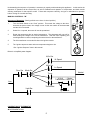
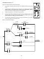
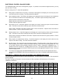
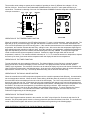
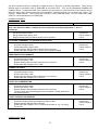
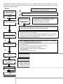
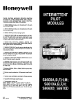
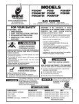
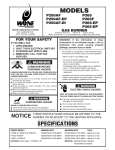
GARLAND
A WELBILT COMPANY
BUILT TO LEAD... BUILT TO LAST
SERVICE MANUAL
THE “MASTER”
GAS CONVECTION
OVENS
Models covered in this manual are:
MCO-GS-10M:
MASTER CONVECTION Oven - GAS STANDARD DEPTH -(10)SINGLE DECK Manual CONTROL
MCO-GS-10E:
MASTER CONVECTION OVEN - GAS STANDARD DEPTH -(10)Single DECK ELECTRONIC CONTROL
MCO-GD-10M:
MASTER CONVECTION Oven - GAS DEEP DEPTH -(10)SINGLE DECK Manual CONTROL
MCO-GD-10E:
MASTER CONVECTION Oven - GAS DEEP DEPTH -(10)SINGLE DECK ELECTRONIC CONTROL
GARLAND Commercial Industries, Inc.
185 East South Street Freeland, Pennsylvania 18224
DIRECT “ON-SITE” SERVICE 1-800-451-1165 GENERAL INFORMATION 1-800-424-2411
FORM #GCI-MCOVN
PRINTED IN THE U.S.A.
This service manual is designed to answer questions related to model operational requirements,
troubleshooting and disassembly/assembly procedures. It contains electronic ignition operation, troubleshooting and electronic control operations that include diagnostic codes, ladder diagrams, wire diagrams and
troubleshooting. It also includes BTU ratings, orifice size and gas pressure technical data for each model.
For example; if you need to know information on manual controls (manual controls - controls the oven with hydraulic
thermostat, electric mechanical timer.) refer to SECTION 2: OVERVIEW OF OPERATIONAL SEQUENCES,
Sequence of Operation. This book is broken down into sections, each section will list the applicable topics. Use the
Table of Contents to locate the topic and function that you are attempting to trouble-shoot.
Table of Contents
SECTION 1: SPECIFICATION & DIMENSIONS ............................................................................3
GAS CONVECTION OVEN "GAS SPECIFICATIONS”...............................................................................................4
DIMENSIONS & SPECIFICATIONS ............................................................................................................................4
SECTION 2: OVERVIEW OF OPERATIONAL SEQUENCES .......................................................4
MANUAL CONTROLS - "M” .......................................................................................................................................5
Sequence of Operation.............................................................................................................................................5
Manual Ladder Diagram ...........................................................................................................................................5
CALIBRATION OF THERMOSTAT .............................................................................................................................5
Instrumentation.........................................................................................................................................................5
Weighting..................................................................................................................................................................6
Thermostat Operation...............................................................................................................................................7
ELECTRONIC CONTROLS - “E” ................................................................................................................................8
Sequence of Operation (With the Oven Doors Closed) ...........................................................................................8
Electonic Ladder Wire Diagram................................................................................................................................8
ELECTRONIC CONTROL FAILURE CODES .............................................................................................................9
CHART FOR INTERNAL OVEN TEMPERATURE SENSOR......................................................................................9
ROBERTSHAW COM6000 CONTROLLER................................................................................................................9
USER PREFERENCE OFFSET FOR THE ELECTRONIC CONTROLLERS ...........................................................10
COM6000 UPO MODE...........................................................................................................................................11
COM6700 UPO MODE...........................................................................................................................................11
ELECTRONIC PILOT & MAIN BURNER IGNITION SEQUENCE ............................................................................12
FIRST STAGE - TRIAL FOR PILOT IGNITION .....................................................................................................12
SECOND STAGE - MAIN BURNER OPERATION ................................................................................................12
SAFETY LOCKOUT TIME......................................................................................................................................12
SERVICE ....................................................................................................................................................................13
PRELIMINARY CHECK..........................................................................................................................................13
SYSTEM TROUBLE SHOOTING...........................................................................................................................13
S86 CHECKOUT AND TROUBLE SHOOTING .....................................................................................................14
CHECK SPARK IGNITION CIRCUIT .....................................................................................................................15
CONTROL MODULE FLAME SENSOR CIRCUIT.................................................................................................15
2
SECTION 3: COMPONENT ACCESS OF FUNCTIONAL COMPONENTS.................................. 16
DOOR GASKET REPLACEMENT............................................................................................................................ 17
TO REMOVE DOORS FROM THE OVEN................................................................................................................ 18
INSTALLATION OF OVEN DOORS ......................................................................................................................... 19
INSTALLING AND ADJUSTMENT OF THE DOOR CHAIN..................................................................................... 19
DISASSEMBLY OF THE LEFT DOOR..................................................................................................................... 19
DISASSEMBLY OF THE RIGHT DOOR (W/O WINDOW) ....................................................................................... 20
TO REPLACE OR ADJUST DOOR LATCH MECHANISM...................................................................................... 22
TO REPLACE CONVECTION OVEN MOTOR ASSEMBLY .................................................................................... 22
CONVECTION OVEN MOTOR ASSEMBLY ............................................................................................................ 23
MAIN BURNER, PILOT BURNER & DOOR MICRO-SWITCH LOCATION ............................................................ 24
SECTION 4: COMMON WIRE DIAGRAMS ................................................................................. 25
SECTION 1: SPECIFICATION & DIMENSIONS
3
GAS CONVECTION OVEN "GAS SPECIFICATIONS”
MAIN
BURNER
ORIFICE
TOTAL
B.T.U.'S
ORIFICE
AMT.
GAS
PRES. W/C
NAT PRO
PILOT
ORIFICE
AMT.
PILOT
ORIFICE
*
NAT
40,000
MCO
PRO
NAT
PRO
**
4.5"
5
/64”
#55
2
.020"
.012"
1
10.0"
(.0781”)
60,000
MCO
5
/64”
5.0”
4.5"
#55
3
.020"
.012"
1
10.0"
(.0781”)
80,000
MCO
5
/64”
5.1”
4.5"
#55
4
.020"
.012"
1
10.0"
(.0781”)
5.5”
* - Gas pressure measured at burner manifold. ** - Gas pressure measured at redundant gas valve
pressure tap.
All models (single deck ovens) amperage rating is 6.2 (each oven). Manifold size is ¾" N.P.T. (National
Pipe Thread). NOTE: Two-speed motor, 1140 and 1725 R.P.M., 60 Hz, clock-wise motor rotation looking
into oven cavity. NOTE: Each deck supplied with a 6 ft. power supply cord for 120-volt units.
DIMENSIONS & SPECIFICATIONS
1-1/2
[38mm]
1-1/2
[38mm]
1/2 N.P.T.
[13mm]
GAS INLET
1-7/8
[48mm]
7-3/4
[197mm]
REAR GAS INLET
32
[813mm]
1-7/16
[37mm]
32
[813mm]
43-1/4 DEEP
54-9/16 [1099mm] DEEP
[1386mm] 39-1/4 STD
57-1/2
[1461mm]
3/4 N.P.T.
[19mm]
GAS INLET
2-3/8 x 5
[60mm x 127mm]
FLUE
38-1/4
[972mm]
70-1/2
[1791mm]
32
[813mm]
[997mm] STD
38
[965mm]
35-9/16
[903mm]
32
[813mm]
25-1/2
[648mm]
17-3/4
[451mm]
Single Deck (Front View)
19
[483mm]
6-1/2
[165mm]
38
[965mm]
38
[965mm]
(Top View)
Double Deck (Front View)
Model #
MCO-GS-10
MCO-GS-20
MCO-GD-10
MCO-GD-20
INTERIOR DIMENSIONS (per oven)
W
H
D
29”(736mm)
24”(610mm)
24”(610mm)
29”(736mm)
24”(610mm)
24”(610mm)
29”(736mm)
24”(610mm)
28”(711mm)
29”(736mm)
24”(610mm)
28”(711mm)
Model #
MCO-GS-10
MCO-GS-20
MCO-GD-10
MCO-GD-20
EXTERIOR DIMENSIONS
W
H (w/legs)
D
38”(965mm)
57½”(1460mm)
39”(991mm)
38”(965mm)
70½”(1791mm)
39”(991mm)
38”(965mm)
57½”(1460mm)
43”(1092mm)
38”(965mm)
70½”(1791mm)
43”(1092mm)
INPUT CHART - Natural or Propane Gas
KW
BTU/HR
Equiv.
Gas Inlet
60,000
17.6
One @ ¾” NPT
120,000
35.2
One @1” NPT
60,000
17.6
One @ ¾” NPT
120,000
35.2
One @ 1” NPT
SHIP WEIGHT/DIM
Lb./KG
Cu. Ft.
510/232
42 cu. ft.
1020/464
84 cu. ft.
510/232
42 cu. ft.
1020/464
84 cu. ft.
ELECTRICAL CHARACTERISTICS
120V/1 Phase
One @ 6.2 Amps
Two @ 6.2 Amps
One @ 6.2 Amps
Two @ 6.2 Amps
240V/1 Phase
One @ 3.1 Amps
Two @ 3.1 Amps
One @ 3.1 Amps
Two @ 3.1 Amps
SECTION 2: OVERVIEW OF OPERATIONAL SEQUENCES
4
Motor
½ HP
½ HP
½ HP
½ HP
Understanding the sequence of operation is necessary in properly trouble-shooting this appliance. In this section the
sequence of operation will be covered first, as well as calibration and operation of components, and basic trouble
shooting techniques for that specific model. Follow each sequence carefully, and get to understand its operation
before moving on to trouble shooting.
MANUAL CONTROLS - "M"
Sequence of Operation (Starting with the oven doors in closed position.)
1.
Turn the Mode Switch to the “Cook” position. This sends line voltage to the timer.
And with the doors closed, line voltage is sent via the door switch to the thermostat
and the Hi/Lo Fan switch.
COOK
O
F
F
POWER
ON
COOL
DOWN
2.
Select Hi or Lo speed, the motor will now be operational.
3.
Rotate the temperature dial to desired temperature. The thermostat will now call for
heat sending line voltage to the 24 volt transformer. With the motor operating, the
centrifugal switch is closed, completing the neutral circuit to the transformer.
4.
The 24v transformer now sends 24 volts to the ignition module.
5.
The *ignition sequence starts and oven temperature begins to rise.
HIGH
LOW
TIMER
TEMP
*See “Ignition Sequence” later in this manual.
Below is a simplified power diagram:
Hi/Lo Sw.
Hi Speed
Hi/Lo Sw.
Lo Speed
Door Sw.
Mode Sw.
Neutral
Timer
Motor
24 Volt
Transformer Centrif. Sw.
Line
Thermostat
Light Sw.
Ign. Module
CALIBRATION OF THERMOSTAT
INSTRUMENTATION
5
A thermocouple type test instrument is preferred for measuring oven temperatures accurately. Mercury thermometers
are acceptable providing they can be proven accurate.
Regardless of the type instrument used, it is most desirable to double-check it just before making an oven temperature
check. This can be done simply and quickly by placing the thermocouple tip (or immersing the entire mercury
thermometer) in boiling water. Note: Mercury oven thermometers should be the "total immersion type." The
resulting reading should be within several degrees of 212°, -depending on the altitude.
Generally, a mercury thermometer can drop in excess of 25° when the doors are opened to check oven tem perature.
This condition makes it extremely difficult to get a true temperature reading.
Almost all ranges today have oven burners which cycle "on and off." The high and low points of the resulting
temperature "swing" (differential) in the oven must be measured-and averaged-to determine the true operating
temperature. A thermocouple type test instrument is best suited to measure these temperature changes quickly and
accurately, and without opening the oven door.
With an accurate, thermocouple test instrument or mercury thermometer, it is still difficult to measure these changing
oven temperatures and then, average them correctly. This is why we recommend that the thermocouple tip or the bulb
of the thermometer be "weighted." Weighting (adding mass) to the test instrument compensates for oven temperature
changes by making the test instrument less sensitive to these constant changes in temperature. Note: How this
weighting can be done is discussed later.
Measuring these changing high and low temperatures points in an oven is possible with either type of test device
without weighting but is subject to possible inaccuracies. This is most true at low temperature setting because, in this
area, the function of "time" becomes a factor. The simple averaging of temperatures, then, may not produce the true
operating temperature. "Weighting" provides the compensation for both time and temperature that is necessary.
We produced (next page) test curves showing actual results in the low temperature area showing the difference in
results when using an unweighted and a weighted thermocouple or thermometer. Tests were made with the same
control, same oven and dial at 170° mark (not move d).
Chart No.1
Chart No.2
260
240
220
200
180
160
140
120
100
260
240
220
200
180
160
140
120
100
Unweighted Thermocouple dial setting 170 F
Weighted Thermocouple Dial Setting 170F
From the above, it can be seen that an error of 15° is possible. Chart #1, unweighted thermocouple indicates an
erroneous average oven temperature of 185°. Chart #2, weighted thermocouple indicates the "average" or true
temperature to be 170°.
WEIGHTING
A thermocouple can be weighted by clamping the tip between two one-inch squares of 1/16" thick aluminum. The
thermocouple can also be weighted (just as successfully) by using a letter-size sheet of aluminum foil. Fold the foil
6
five times doubling the thickness with each fold. After the fifth fold, place the thermocouple tip in the center of the
aluminum piece and fold once more. Finally, fold in the sides so that the foil clings to the thermocouple tip.
A mercury thermometer can be weighted in much the same way by wrapping several layers of aluminum foil around
the bulb end thus creating the necessary mass. This procedure is a must if you open an oven door to check
temperature.
THERMOSTAT OPERATION
It is normal for a hydraulic thermostat cycling with a temperature swing of 45° to 50°. When checking calibration first;
allow the thermostat to cycle a minimum of four (4) times, second; place your temperature sensor in the geometric
center of the empty oven. Once the oven has been allowed to preheat record the temperature at which the burners
cycle "ON and OFF". Average the two readings, that average should be +-20° of the set point temperatu re.
Example: Thermostat set point at 300°, first cycl e Off at 325°. Cycle back ON at 291°. The average of 325° and
291° is 308°. This thermostat is with the +-20° to lerance. If the thermostat is cycling beyond the 20° tolerance and the
appliance is under warranty recalibrate the thermostat or if not under warranty consult owner for proper action. If
the thermostat is out of calibration more than fifty 50°, it will not likely hold an attempt of recalibration, we suggest that
the thermostat be replaced.
"B" Dial Shaft
Increase
"A" Calibration Screw Head
Decrease
1/4" Turn
- CALIBRATION NOTES -
7
ELECTRONIC CONTROLS - “E”
Sequence of Operation (With the Oven Doors Closed)
COOK
1.
Line Voltage is supplied to the Mode Switch, Door Switch and the Momentary Light
Switch.
2.
Set Mode Switch to COOK and close the oven doors. Line Voltage is sent from Mode
Switch to power up the Controller and to the AUX relay on the controller. With the
oven doors closed Line Voltage is sent to the 24 volt transformer.
3.
Set desired temperature. The controller’s relays now close.
4.
The AUX relay sends Line Voltage to the motor relay coil, closing the circuit to the
Hi/Lo Fan Switch. The motor now operational causes the centrifugal switch to close
and send the Neutral Voltage to the 24 Volt Transformer.
COOL
DOWN
LOW
- +
- +
START
TIMER
CANCEL
TIMER
TIMER
0-12 HOUR
5.
HIGH
HEAT
O
F
F
TEMP
140-500F
The bake relay completes the circuit from the 24 volt transformer to the ignition
module and *ignition occurs, heating the oven.
Below is a simplified power diagram:
24 Volt
Motor
Centrifugal Switch
Transformer
24 V
Thermostat
Ign. Module
Door Sw.
Hi Speed
Motor Relay
Lo Speed
Neutral
AUX
Mode Sw.
COM6000
Light Sw.
8
ELECTRONIC CONTROL FAILURE CODES
The GARLAND digital control has a self-diagnostic program. If a problem occurs within the digital controller, you may
see one of the "F" codes.
Below is a listing of the "F" codes with explanations:
-F1-
Relay output is enabled when not cooking. If this failure code appears in the display, the cook relay may be on
even if the control is not cooking. The control should be replaced.
-F2-
Over temperature alarm. If this failure code appears in the display the control is sensing an oven temperature
50° or more above the maximum set temperature (500°). This failure may be caused by a faulty sensor.
Check the sensor connection for loose wires.
Replace the sensor and check for proper operation.
If failure continues replace the control.
-F3-
Open sensor circuit. If this failure appears in the display, the control is sensing an open circuit at the sensor
input. This failure is most often caused by a poor connection or broken sensor.
Check sensor connection and leads for broken wires of loose connections. Replace sensor and check for
proper operation. If failure continues replace control.
-F4-
Shorted sensor circuit. If this failure appears in the display, the control is sensing a short circuit at the sensor
input. This failure is most often caused by loose wires at the connection of shorted sensor leads.
Check sensor connection and leads for loose wires. Replace sensor and check for proper operation. If failure
continues replace control.
-F5-
Relay outputs not enabled when cooking. If this failure appears in the display the control cannot turn the
relays on even when cooking. The control should be replaced.
-F6-
No 60 Hz input. The control does not sense the input power. This failure mode is most often the result of a
failed component in the control. However, this failure may also be the result of a very noisy power line. Look
for any large electrical noise producing machinery (such as mixers, compressors, dishwashers etc.). If
possible, turn these machines off. Reapply power to the oven. If the failure repeats, replace the control. If
the failure does not repeat, an electronic control may not work in this application because of noise. You must
isolate the supply circuit.
-F7-
The control has detected that calculated EEPROM check sum is not the same as the expected check sum
retrieved from the EEPROM. When the control detects this error code, it will disable outputs before the alarm
sounds.
RESISTANCE vs. TEMPERATURE CHART FOR INTERNAL OVEN TEMPERATURE SENSOR
The chart below will provide the Ohms at various temperatures. This will enable you to determine if the temperature
probe is operable.
The chart is in Degrees Fahrenheit. How to use chart, for 350°, read down to 300 then across to 50, answer is
1654Ohms of resistance.
TEMP
0°
100°
200°
300°
400°
500°
0°
932
1143
1350
1553
1753
1949
10°
953
1163
1370
1574
1773
1969
20°
974
1184
1391
1594
1793
1988
30°
995
1205
1411
1614
1813
2008
40°
50°
60°
70°
80°
90°
1016
1038
1059
1080
1101
1122
1226
1247
1267
1288
1309
1329
1432
1452
1472
1493
1513
1533
1634
1654
1674
1694
1714
1733
1832
1852
1871
1981
1911
1930
2027
2046
2065
2085
2104
2123
ROBERTSHAW COM6000 CONTROLLER
9
The controller needs voltage to operate and is capable of operating on three (3) different line voltages, 115 Vac,
208 Vac, 240 Vac. On the back of the Robertshaw COM6000 there are several ¼” male spade terminal or pin
connections. The below is a drawing of the rear of a Robertshaw COM6000 Controller along with a definition of each
of the pin connections.
240V
208V
120V
NEUTRAL
E5 E4 E3 E2
AUX
E9
E10
BAKE
DOOR
E1
GROUND
E11
E12
E6
E8
E7
PROBE
REAR VIEW
- +
- +
START
TIMER
CANCEL
TIMER
FRONT VIEW
OPERATION OF THE TEMPERATURE FUNCTION
When the controller is powered up, the LED will be illuminated. To enter a cook temperature, rotate the right dial. The
digits will go up as you rotate the dial to the right and decrease if rotated to the left. The controller determines if the
oven is at set temperature by the RTD sensing probe. If the controller senses that the oven is below the displayed set
temperature, the controller activates the bake relay, calling for heat. At the same time the temperature digits begin to
blink indicating that the controller is calling for heat. Once the controllers’ set temperature is satisfied the temperature
digits will stop flashing and remain constant, and deactivating the bake relay. NOTE: The temperature digits will
remain constant unless the set temperature is altered. If altered, the digits will again blink until the new set
temperature is reached. The controller will hold a tolerance of +/- 5°. To access the actual oven temperature, depress
the start key for three (3) seconds and the temperature will now display the actual oven temperature.
OPERATION OF THE TIMER FUNCTION
To enter a desired cook time rotate the left time dial. The digits will display, (in the first hour), minutes & seconds.
Above the first hour, the timer will display in hours & minutes. The diplay will continue to blink until the “START
TIMER” key is depressed. The resolution of the timer can be altered to display only hours and minutes if desired, see
User Preference Programming in the following pages. At the end of the timed period an alarm will sound until operator
depresses the “Cancel Timer” key. The timer (in standard mode), has no effect on the bake relay.
OPERATION OF THE COOK’n HOLD FUNCTION
When the controller has a HOLD temperature programmed, the controller operates a little differently. As noted earlier,
set cook temperature and time. When the timer counts down to 00:00 the alarm will sound for five (5) seconds and
the word HOLD will now be displayed in the time side of the LED display. The “AUX” relay will also be deactivated at
this time and stop the oven fan. At the same time the cook temperature will change to the new hold temperature that
was preprogrammed in the controller. This new temperature will now blink, indicating that a new set temperature must
be reached. Once this new set temperature is reached the digit will go constant. After reaching the new set
temperature the “AUX” relay (oven fan) and “Bake” relay (heat) will cycle together. To cancel, depress the “Cancel
Timer” key on the control. This controller will remain in this COOK’n HOLD program until removed, see User
Preference Programming in the following pages.
OPERATION OF THE PULSE FUNCTION
When Pulse Program has been entered in the controller, the “AUX” relay will open for 30 seconds and close for 30
seconds. The 30 seconds open & closed is a factory preset time and cannot be altered in the field. The controller will
remain in this Pulse Program until removed, see User Preference Programming in the following pages.
USER PREFERENCE OFFSET FOR THE ELECTRONIC CONTROLLERS
10
The User Preference Offset is designed to enable the user to adjust the controlling temperature. There are two
different styles of controllers used by GARLAND at the present time. They are the Robertshaw COM6000 and
COM6700 Series. To determine which of the controllers you are working on, look at the back of the controller and you
will see a sticker with a printed number like “PN:100-289-03”, below this number is the controller style number. For
example: COMA-6704-GL. This indicates that controller is in the COM6700 Series. Or if the number was “COM6000-GA” it would indicate that it is a COM 6000.
COM6000 UPO MODE
Entry
Exit
UPO - User Preference Offset. Used by the user to adjust the controlling temperature +/- 50º in 1º
increments.
1.
2.
3.
Set the time digits to 00:00.
Set the temperature digits to X10º.
Depress both the Start and Cancel buttons for five seconds.
1.
Depress the
Cancel button to
lock-in
1.
Depress the
Cancel button to
lock-in.
1.
Depress the
Cancel button to
lock-in.
1.
Depress the
Cancel button to
lock-in.
1.
Depress the
Cancel button to
lock-in.
1.
Depress the
Cancel button to
lock-in.
TO CHANGE FAHRENHEIT TO CELSIUS (and vise versa)
1.
2.
3.
4.
Set the time digits to 00:00.
Set the temperature digits to X20º.
Depress both the Start and Cancel buttons for five seconds.
Rotate either dial to display FFF or CCC in the temperature display
TIMER RESOLUTION CHANGING
1.
2.
3.
4.
Set the time digits to 00:00.
Set the cook temp to X30º
Depress both the Start and Cancel buttons for five seconds.
Rotate either dial to display “HR” or “MN”.
CHANGE THE HERTZ
1.
2.
3.
4.
Set the time digits to 00:00.
Set the cook temp to X40º
Depress both the Start and Cancel buttons for five seconds.
Rotate either dial to display “50” or “60” Hz.
TO SET HOLD TEMPERATURE
1.
2.
3.
4.
Set the time digits to 00:00.
Set the cook temp to X50º
Depress both the Start and Cancel buttons for five seconds.
The word “hold” will now be displayed in the time display. Rotate either dial to
set hold temperature.
TO SET OVEN INTO PULSE MODE
1.
2.
3.
Set the time digits to 00:00 and temperature digits to 000°.
Depress both the Start and Cancel buttons.
Rotate either dial to display “con” for continuous operation or “cyc” for cycling
fan on & off.
COM6700 UPO MODE
11
Entry
Exit
UPO - User Preference Offset. Used by the user to adjust the controlling temperature +/- 50º in 1º
increments.
1.
2.
3.
4.
Set the time digits to 00:00.
Set the temperature digits to X10º.
Depress & hold the Start button for five seconds.
“UPO” & Current UPO will be displayed. Turn TEMP or TIME dial to adjust.
1.
Depress the
Actual Temp
button to lock-in.
1.
Depress the
Actual Temp
button to lock-in.
1.
Depress the
Actual Temp
button to lock-in.
1.
Depress the
Cancel button to
lock-in.
1.
Press Pgm
Mode on/off to
exit program
mode.
TO CHANGE FAHRENHEIT TO CELSIUS (and vise versa)
1.
2.
3.
4.
Set the time digits to 00:00.
Set the temperature digits to X20º.
Depress & hold the Start button for five seconds.
Rotate either dial to display FFF or CCC in the temperature display
TIMER RESOLUTION CHANGING
1.
2.
3.
4.
Set the time digits to 00:00.
Set the cook temp to X30º
Depress & hold the Start button for five seconds.
Rotate either dial to display “HR” or “MN”.
CHANGE THE HERTZ
1.
2.
3.
4.
Set the time digits to 00:00.
Set the cook temp to X40º
Depress & hold the Start button for five seconds.
Rotate either dial to display “50” or “60” Hz.
CHAIN PROGRAMMING
1.
2.
3.
4.
5.
Press Pgm Mode on/off.
Select Pgm # (1-5).
Enter Event 1 parameters (time, temp, fan speed etc.). Press Event # key to
nd
chain 2 event.
Enter Event 2 parameters.
Continue procedure up to six events.
ELECTRONIC PILOT & MAIN BURNER IGNITION SEQUENCE
FIRST STAGE - TRIAL FOR PILOT IGNITION
On every call for heat (system start), the S86 performs an internal safe-start check shows that a flame-simulating
condition is present. During a normal start, the S86 opens the pilot valve in the gas control. This allows gas to flow to
the pilot burner. Simultaneously, the electronic spark generator in the S86 produces a 15,000 volt spark pulse output.
This voltage produces a spark at the pilot burner ignitor/sensor rod, igniting the gas flowing around the electrode. If
the pilot flame is not detected during the trial for pilot ignition, the S86H contains a safety lockout timer (90 Seconds) to
limit the trial for pilot ignition period.
SECOND STAGE - MAIN BURNER OPERATION
When the pilot flame is established, a flame rectification circuit is completed to the burner ground. The S86 flame
sensing circuit detects the flame current and shuts the spark generator off. At the same time, the second operator
(main gas valve) is opened in the gas control, allowing gas flow to the main burners. The pilot flame ignites the main
burner conventionally.
SAFETY LOCKOUT TIME
12
The safety lockout timer circuit starts timing the moment the trial for pilot ignition starts. When the timing period runs
out, the trial for ignition ends, and the control module goes into lockout. Before another attempt to start can be made,
the S86 must be reset. Reset by adjusting the thermostat or controller or to its "OFF" position. An alternate method is
to shut the system power "OFF". If normal ignition does not occur, use the trouble shooting table to determine the
problem.
START
STAGE 1
TRIAL FOR
IGNITION
1
THERMOSTAT (CONTROLLER) CALLS
FOR HEAT
2
SPARK GENERATOR POWERED
First valve (pilot) operator opens
3
PILOT BURNER OPERATION
Pilot burner lights.
OR
Module senses flame
current.
STAGE 2
MAIN BURNER
OPERATION
4
•
•
Pilot burner does not light.
a
After 90 second system
locks out; must be manually
reset.
a
Shutoff/lockout timing is stamped on module.
FLAME CURRENT SENSED
Spark generator off.
Second valve operation (main) opens.
5
MAIN BURNER OPERATION
Module monitors pilot flame current.
6
POWER INTERRUPTION
System shuts off, restarts
when power is restored.
PILOT FLAME FAILURE
Main valve closed.
Module starts trial for ignition.
THERMOSTAT (CONTROLLER) SATISFIED
END
Valves close, pilot and main burners are off.
SERVICE
PRELIMINARY CHECK
The following visual checks should be made before trouble shooting and after installation or maintenance.
1. Check power to appliance and S86.
2. Manual shutoff cocks in gas line to appliance must be open.
3. Make certain all wiring connections are clean and tight.
4. First de-energize the system and wait at least one (1) minute. This resets the module allowing a return to start
condition. Then energize the system.
5. Review the S86 system normal sequence of operation.
SYSTEM TROUBLE SHOOTING
Start the system by setting the thermostat or controller above required temperature. Observe system response.
Establish type of malfunction or deviation from normal operation. Use the S86 Intermittent Pilot System Trouble
Shooting Table to check for normal system operation.
Use table by following instruction questions in box. If the condition is true or okay (answer yes), go down to next box
underneath. If the condition is not true or not okay (answer no), go right to the next box alongside. Continue checking
13
and answering conditions in each box encountered, until a problem and/or the repair is explained. After any
maintenance or repair, the trouble shooting sequence should be repeated until the trouble shooting procedure ends
with a normal system operation.
START
NOTE: Before troubleshooting, familiarize yourself
with the startup and checkout procedure.
TURN GAS SUPPLY OFF.
TURN THERMOSTAT
(CONTROLLER) TO CALL
FOR HEAT
POWER TO MODULE (24v
NOMINAL)
NO
Check line voltage power, low voltage transformer, limit controller, thermostat
(controller) and wiring.
•
Pull ignition lead and
check spark at module.
YES
NO
SPARK ACROSS
NO
IGNITOR/SENSOR GAP
•
Spark okay?
On models with vent damper plug, make sure vent
damper had not been installed, then remove.
Replace vent damper if necessary.
On other models, replace module.
YES
•
•
Check ignition cable, ground wiring, ceramic insulator and gap, and correct.
Check boot of the ignition cable for signs of melting or buckling. Take protective
action to shield cable and boot from excessive temperature.
•
Check that all manual gas valves are open, supply tubing and pressure are good,
and pilot burner orifice is not blocked.
Check electrical connections between module and pilot operator on gas control.
Check for 24 Vac across PV-MV\PV terminals on module. If voltage is okay,
replace gas control; if not, replace module.
YES
TURN GAS SUPPLY ON
•
•
NO
PILOT BURNER LIGHTS?
YES
•
SPARK STOPS WHEN
•
PILOT IS LIT?
NO
•
•
•
•
YES
•
MAIN BURNER
LIGHTS?
NO
•
•
YES
SYSTEM RUNS UNTIL
NO
CALL FOR HEAT
LOSS?
YES
CALL FOR HEAT ENDS
SYSTEM SHUTS OFF? NO
YES
TROUBLESHOOTING
ENDS
•
•
•
•
•
NOTE: If S8600B,H; S8610B, H goes into lockout, reset system. For S8600M,
wait 6 minutes nominal for retry or reset system.
Check continuity of ignition cable to ground wire.
Clean flame rod.
Check electrical connection between flame rod and module.
Check for cracked ceramic flame rod insulator.
Check that pilot flame covers rod and is steady and blue.
Adjust pilot flame.
If problem persists, replace module.
Check for 24 Vac across MV-MV\PV terminals. If no voltage, replace module.
Check electrical connections between module and gas control. If okay, replace
gas control or gas control operator.
NOTE: If S8600B,H; S8610B, H goes into lockout, reset system. For S8600M,
wait 6 minutes nominal for retry or reset system.
Check continuity of ignition cable and ground wire.
NOTE: If ground is poor or erratic, shutdowns may occur occasionally even
though operation is normal at the time of checkout.
Check that pilot flame covers flame rod and is steady and blue.
If checks are okay, replace module.
Check for proper thermostat (controller) operation.
Remove MV lead at module; if valve closes, recheck temperature controller and
wiring; if not, replace gas control.
Repeat procedure until troublefree operation is obtained.
S86 CHECKOUT AND TROUBLE SHOOTING
14
CHECK GROUNDING
A common ground is required for the pilot burner, the ignitor-sensor, the GND terminal of the S86, and the main
burner. The main burner generally serves as the common ground. If the ground is poor or erratic, safety shutdowns
may occur occasionally even though operation is normal at the time of the checkout. Therefore, if nuisance
shutdowns have been reported, be sure to check the grounding.
NOTE:
If the ground circuit path is incomplete, the S86H system control will allow one trial-for-ignition
before going into safety lockout.
Electrical grounding connections at the pilot burner, ignitor/sensor and S86 must be clean and tight. If lead wire is
damaged or deteriorated, use only No. 14 of 18 gauge, moisture-resistant, thermoplastic insulated wire with 105°C.
(221°F) minimum rating as replacement. Excessive temperature at the ceramic flame rod insulator can also permit
electrical leakage to ground. Examine the flame rod and mounting bracket, and correct if bent out of position.
Replace ignitor/sensor of insulator is cracked.
CHECK SPARK IGNITION CIRCUIT
The electronic module and step-up transformer in the S86 provides spark ignition at 15,000 Volts (open circuit). This
circuit can be checked at the S86 module as follows:
1.
Turn off the manual gas cock to prevent the flow of gas.
2.
Disconnect the ignition cable at the S86 stud terminal to isolate the circuit from the pilot burner/ignitor/sensor, and
prepare a short jumper lead using heavily insulated wire, such as ignition cable.
3.
Energize the S86. Touch one end of the jumper firmly to the S86 ground terminal (GND). Do not disconnect the
existing ground lead. Move the free end slowly toward the stud terminal to establish a spark and then pull the
lead wire slowly away from the stud. Note the length of the gap at which arcing stops.
CAUTION:
4.
Do not touch either stripped end of jumper or stud terminal. This is a very high voltage circuit
and electrical shock can result. Perform the test immediately upon energizing the system before the S86H goes into safety lockout and interrupts the spark circuit.
An arc length of 1/8" (3.2 mm) or more indicates satisfactory voltage output. Replace the S86 if no arc can be
established or the maximum gap is less than 1/8" (3.2 mm), and the fuse and power to the S86 input terminal
was okay.
CONTROL MODULE FLAME SENSOR CIRCUIT
The control module provides AC power to the ignitor/sensor which the pilot burner flame rectifies to direct current. If
the flame signal back to the control module is not at least 1.0 µA DC, the system will lockout. The output of the flame
sensing circuit cannot be checked directly, so check the flame sensing circuit indirectly by checking the flame sensing
current from the ignitor/sensor to the control module as follows:
1.
Connect a meter (DC micrometer scale) in series with the flame signal ground wire (Burner Ground Terminal).
Disconnect the ground wire at the control module. Connect the red (positive) lead of the meter to the free end of
the ground wire. Connect the black (negative) meter lead to the quick-connect ground terminal on the control
module.
2.
Restart the system and read the meter. The flame sensor current must be at least 1.0 µA, and the reading must
be steady. If the reading is below the value designated or the reading is unsteady, check the pilot flame and
electrical connections as described above. Also, replace the ignitor/sensor if the ceramic insulator is cracked.
EXAMPLES OF UNSATISFACTORY PILOT FLAMES
15
APPEARANCE
CAUSE
SMALL BLUE FLAME
Check for lack of gas from:
• Clogged orifice filter
• Clogged pilot filter
• Low gas supply pressure
• Pilot adjustment at minimum
LAZY YELLOW FLAME
Check for lack of air from:
• Large orifice
• Dirty lint screen, if used
• Dirty primary air opening, if there is one
• Pilot adjustment at minimum
WAVING BLUE FLAME
Check for :
• Excessive draft at pilot locations
• Recirculating products of combustion
NOISY LIFTING BLOWING FLAME
HARD SHARP FLAME
Check for:
• High gas pressure
This flame is characteristic of manufactured gas
Check for:
• High gas pressure
• Orifice too small
SECTION 3: - ACCESS OF FUNCTIONAL COMPONENTS
16
This section will give you the best way to access component for replacement.
COMPONENT LOCATIONS:
Top Front Center
Door Chain
Door Catch
Right Front
Control Panel
24v Transformer, Ignition module
Redundant gas valve
Lower Front
Door Micro-Switch
Data Plate, Burner Package
Inside Oven
Oven Convection Motor
Oven Interior Lights
Single Deck (Front View)
Door Gasket Replacement
1.
Open oven doors
17
2.
3.
4.
5.
Locate stainless steel door gasket, mounted to oven front frame.
Remove the #10 Phillips sheet metal screw that attach the retainer to the oven's front
frame.
Remove stainless steel door gasket.
Replace stainless steel door gasket and to reverse above procedure to re-install.
1
2
2
3
To Remove Doors from the Oven
1.
Remove top front cap veneer. 18
FILE NAME
JIT03418
2.
3.
4.
5.
Remove door chain assembly (NOTE: The “A” model does not come equipped with door
chain).
Remove flat head metal screw 1/4”-20x1/2” from bearing retainer.
Push the door toward hinge and lift up. NOTE: Bottom bearing retainer will stay in place.
Remove the right door in the same manner.
1
2
3
FILE NAME
JIT03459
4
To Reinstall Doors onto Convection Oven
1.
2.
3.
Reverse procedure above.
Close doors.
Reinstall the door chain.
2 Links
Installing and Adjusting Door Chain
4.
5.
6.
Make sure two links are between
sprocket and door rod, and there
should be 8 regular links plus one
8 Links
master link on the forward side of
each chain.
Tighten up turn buckles, the right
door should close approximately ½”
Turnbuckles
before the left door.
Secure the turnbuckles by tightening
Locking Nuts
lock nuts.
Door Stop Bolt
Disassembly of the Left Door
19
NOTICE: DEPENDENT DOOR SHOWN
6
3
7
4
5
8
2
7
1
7
To disassemble left door:
1. Once the door has been removed from the oven (refer to instructions on the previous page),
remove the 12 truss head 10 x ½ Phillips screws .
2. Remove 2 allen head cap screws from the door handle .
3. Carefully pry off the door panel from the door window bezel .
4. Remove 2 hex head m.s. ¼ -20 x ½ from the door liner that attach hold down straps to
the door liner .
5. Lift out the door frame .
6. Carefully pry off the door window for door liner .
7. To remove door catch remove 2 pan head Phillips screws.
8. To reassemble - reverse above procedure.
There is a seam one side of the bezel that is part of the door window , reinstall
working from the opposite side that the seam is on and work around the window
towards that seam.
Disassembly of the Right Door (w/o window)
NOTE:
20
NOTICE: DEPENDENT RIGHT HAND DOOR SHOWN.
5
1
2
3
4
1. Once the door has been removed from the oven (refer to instructions on page 19), remove 9
truss head s.m.s. 10 x ½ from the top, bottom and left side (as shown) from the door panel
.
2. Pry the door liner apart from the door panel . This will expose the door frame .
3. To reassemble, reverse above procedure.
21
To Replace or Adjust Door Latch Mechanism
1
1. Open oven doors.
2. Remove 2 pan head Phillips screws.
3. Lift door latch mechanism up and out of door
assembly.
4. To adjust latch mechanism , loosen lock nut & and
adjust by tightening or loosening adjustment nut.
3
6
To Replace Convection Oven Motor Assembly
(Drawing Below)
2
1. Open doors and remove all oven racks.
2.
Remove 4 #10 sheet metal screws (that secure air baffle)
and remove air baffle.
3.
4
Remove six hex nut 1/4-20x7/16" (2A) and lock washers
5
(4A) from motor mounting studs.
4.
Place a piece of cardboard on oven floor to protect from
scratching or chipping.
5.
Pull entire motor assembly (1A) away from rear oven wall
into oven cavity and place on cardboard.
6.
Disconnect wiring, be sure to note wire locations.
7.
To reinstall reverse above procedure.
1A
FILE NAME
4A
JIT00024
2A
Convection Oven Motor
22
Assembly
6
2
1
3
7
5
5
FILE NAME
JIT00012
4
8
1.
9
Assemble motor mount plate, * insulation, motor mount plate inner together by
fastening four flat head m.s. 1/4-20x2½" into the four holes noted on the above drawings.
2.
Secure each flat head m.s. 1/4-20x2½" with a flat washer and three hex nuts 1/4-20 .
3.
Attach motor mounting plate to motor . Insert the four flat head m.s. 1/4-20x2½" through
the mounting tabs on motor as shown. Secure with two hex nuts 1/4-20 .
4.
Insert shaft of motor through the hub of the blower wheel . Space the blower wheel ¼" away from the inner motor mounting plate .
5.
Secure the blower wheel to the shaft of the motor by tightening the two set screws on the blower wheel hub. Use a torque wrench and tighten to 180 inch pounds for proper
securing.
***** For warranty replacement we require that you use the motor assembly. Order motor
assembly part # CK1003090 - 2 Speed, 115 Vac, or CK1003091 2 Speed, 208/240 Vac (Export
or Special), CK1003092 - 1 Speed, 115,208,240 Vac.
23
Main Burner, Pilot Burner Removal & Door Micro Switch Location
3
4
2
1
To access the Burners, Pilot or Door Switch - remove the lower combustion chamber, (not show).
This exposes these components, also you will note that the rating or data plate is on the inside of
the combustion shroud.
For ovens that are 80,000 B.T.U.’s there are four burners, 60,000 B.T.U.’s there are three burners
as shown in the above illustration, and 40,000 B.T.U.’s there are two burners. On 40,000 B.T.U.
models the pilot is located where the left or first burner usually is. The two main burners are
located in the center of the burner manifold. By centering the burners it provides more uniform
heating of the oven cavity.
24
SECTION 4: - COMMON WIRE DIAGRAMS
25
26
27
28