1
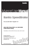
Owner’sManual
with Installation Instructions
Banks Split-Dual
Monster
Exhaust System
Quad-Tip
®
2008 Ford Power Stroke 6.4L
Turbo-Diesel F250/F350 Trucks
THIS MANUAL IS FOR USE WITH SYSTEM 49786 & 49787
Gale Banks Engineering
546 Duggan Avenue • Azusa, ca 91702
(626) 969-9600 • Fax (626) 334-1743
Product Information & Sales: (800) 438-7693
Customer Support: (888) 839-5600
bankspower.com
©2008 Gale Banks Engineering
3/28/08 PN 96547 v.1.0
General Installation Practices
5. Route and tie wires and hoses a
Dear Customer,
If you have any questions concerning the installation of your Banks Power System, please call our Technical Service Hotline at (888) 839-2700 between 7:00 am and 5:00 pm (PT). If you have any questions relating to shipping or billing, please contact our Customer Service Department at (888) 839-5600.
Thank you.
1. Before starting work, familiarize
yourself with the installation procedure
by reading all of the instructions.
2. The exploded view (Figure 1, pages
4-5) provides only general guidance.
Refer to each step and section diagram
in this manual for proper instruction.
3. Throughout this manual, the
left side of the vehicle refers to the
driver’s side, and the right side to
the passenger’s side.
4. Disconnect the negative (ground)
cable from the battery (or batteries, if
there are two) before beginning work.
2
96547 v.1.0
minimum of 6” away from exhaust
heat, moving parts, and sharp edges.
Clearance of 8” or more is recommended
where possible.
6. When raising the vehicle, support
it on properly weight-rated safety
stands, ramps or a commercial hoist.
Follow the manufacturer’s safety
precautions. Take care to balance the
vehicle to prevent it from slipping or
falling. When using ramps, be sure the
front wheels are centered squarely on
the topsides. When raising the front
of the vehicle, put the transmission in
park (automatic) or reverse (manual),
set the parking brake, and block the
rear wheels. When raising the back of
the vehicle, be sure the vehicle is on
level ground and the front wheels are
blocked securely.
Caution! Do not use floor jacks to
support the vehicle while working
under it. Do not raise the vehicle
onto concrete blocks, masonry
or any other item not intended
specifically for this use.
7. During installation, keep the work
area clean. Do not allow anything to
be dropped into intake, exhaust, or
lubrication system components while
performing the installation, as foreign
objects will cause immediate engine
damage upon start-up.
Tools Required:
1⁄ 2”
3⁄ 8”
•
and
drive ratchets with inch and metric sockets and 1⁄ 2” and 3⁄ 8” drive extension
• Inch and metric combination or open-end wrenches
Highly recommended
tools and supplies:
• Foot-pound torque wrench
• Penetrating oil or light
lubricant spray
• Standard screwdriver
• Clean shop towels or rags
• Pry-bar
• Reciprocating saw
96547 v.1.0
3
Figure 1
General Assembly Diagram
Item
Description
P/N
Qty.
1
Intermediate Pipe
53990
1
*2
Intermediate Pipe Extension
53987
1
3
Y-Pipe
53993
1
4
Tail Pipe, Left
53994
1
5
Tail Pipe, Right
53995
1
6
Exhaust Clamp, 3.5”
52468
3
*7
Exhaust Clamp, 4”
52470
1
*8
Hanger Clamp, Intermediate
53986
1
9
Hanger Clamp, Rear
53989
1
10
Frame Hanger Bracket
Nylock Nuts, 7⁄16”-20
53566
1
91617
2
91603
4
13
Washers, 7⁄16”
Hex Bolt, 7⁄16”-20 x 1”
91627
2
14
Rubber Insulator
53732
1
15
Black 5”Cable Tie
62001
3
16
Banks Urocals
96009
2
11
12
* For Crew Cab Long Bed only
* 7
* 8
Factory
Diesel
Particulate
Filter
6
1
4
96547 v.1.0
* 2
5
6
11
14
12
10
13
9
6
3
4
15
16
96547 v.1.0
5
Monster Exhaust System Installation
1. As a precaution, disconnect the
ground of the battery (if there is more
than one battery, disconnect both).
2. Raise the vehicle and support it with
properly weight rated safety stands,
ramps or a commercial hoist. Follow
the manufacturer’s safety precautions.
Take care to balance the vehicle to
prevent it from slipping or falling. When
using ramps, be sure the front wheels
are centered squarely on the topsides;
place the transmission in park; set the
parking brake and place blocks behind
the rear wheels.
CAUTION: DO NOT WORK UNDER
ANY VEHICLE SUPPORTED ONLY
BY A JACK. SEVERE INJURY MAY
RESULT.
WARNING! The following step may
require the use of a torch and/
or saw. Proper safety equipment
should be used. Failure to use
proper safety equipment may
result in severe injury.
3. Starting at the rear of the
vehicle, remove the tailpipe near the
intermediate pipe clamps by cutting
through the connection or by removing
the clamps and heating the joints
with an oxy-acetylene torch to allow
crimped pipes to separate. Remove
the tailpipe from the vehicle.
4. Remove the clamps on the Diesel
Particulate Filter to intermediate
pipe. TAKE CAUTION TO NOT CUT
OR DAMAGE DIESEL PARTICULATE
FILTER TUBING DURING THE
REMOVAL PROCESS. Separate the
intermediate pipe to Diesel Particulate
Filter connection.
6
96547 v.1.0
Note: the use of an oxy-acetylene
torch may be necessary. Remove
the intermediate pipe hanger pins
from the rubber hangers with a pry
bar (Spray lubricant will ease hanger
removal) and remove the intermediate
pipe assembly from the vehicle.
5. Locate the supplied intermediate
pipe and cut the intermediate pipe
based on the following configurations.
See Table 1. Cut the NON-swedged
end of the intermediate pipe. See
Figure 2.
6. Install a 31⁄ 2” exhaust clamp onto
the front of the Banks intermediate
pipe. Install the intermediate pipe onto
the Diesel Particulate Filter outlet.
Loosely snug the 31⁄ 2” clamp.
7. For Crew Cab Long Bed Models
Only, all other models skip to step 9.
Slide the supplied hanger clamp onto
the intermediate pipe. Insert the
hanger pin into the factory rubber
hanger. See Figure 1.
8. Locate the supplied intermediate
pipe extension. Install supplied 4”
exhaust clamp onto the inlet of the
pipe extension. Install extension pipe
onto the intermediate pipe and loosely
snug the exhaust clamp.
9. Install the rear hanger clamp onto
the intermediate pipe outlet with
the hanger pins facing the front of
the vehicle. Insert the two (2) hanger
pins into the rear rubber hangers and
adjust the hanger clamp to a position
that best supports the intermediate
pipe. (see Figure 3).
Cut line
Figure 2
See Table 1 for cutting length
Table 1
2008 Ford Power Stroke 6.4L
Wheel Base
Cut this length from the
Intermediate Pipe. See Figure 2.
Super Cab/ Short Bed
141.8”
20”
Crew Cab/ Short Bed
156.2”
No Cut
Crew Cab/ Long Bed
172.4”
No Cut
Figure 3
Front of
vehicle
96547 v.1.0
7
Figure 4
FACTORY
LEAF STOP
BANKS
HANGER
BRACKET
FACTORY
FRAME
SLOT
BANKS
RUBBER
INSULATOR
BANKS
7/16”
HARDWARE
FORWARD
BANKS
DRIVER SIDE
TAILPIPE
10. Install the Y-pipe over the
intermediate pipe as shown in
Figure 1. Install clamps onto each
Y-pipe outlet.
11. Locate the two slots on the rear
13. Install the driver-side tailpipe onto
the left Y-pipe outlet. Install the driverside tailpipe hanger into the vehicle
rubber insulator. Position the rubber
insulator as shown in Figure 5.
diverside frame rail and install the
supplied Banks hanger bracket using
the supplied hardware. Be sure the
hanger pin is align parallel to the frame
rail and torque the hardware to 48ft-lb.
See Figure 4.
14. Install the passenger-side tailpipe
12. Install the supplied rubber
to the rear of the vehicle and center
between the dual tailpipes. Securely
tighten the spare tire so that it is
retained in place see Figure 6.
insulator onto the Banks hanger
bracket.
8
96547 v.1.0
onto the right Y-pipe outlet. Install the
passenger-side tailpipe hanger into the
vehicle rubber insulator. Position the
rubber insulator as shown in Figure 3.
15. Loosen and move the spare-tire
Figure 5
Figure 6
ADJUST SO THAT
SPARE TIRE TO
HEAT SHIELD CLEARANCE
IS WITHIN 1/2”
MOVE SPARE
TIRE TOWARDS
REAR OF
VEHICLE
BANKS
DRIVER SIDE
TAILPIPE
ZIP TIE ON
VENT HOSE
& BRAKE LINE
BANKS
PASSENGER SIDE
TAILPIPE
96547 v.1.0
9
Figure 7 Placement of template on Passenger side rear undercarriage lining.
16. Adjust the Tailpipe Tips under the
rear fender such that the tip position is
aesthetically pleasing.
17. Use Template 1 and/or 2
on page 14 & 15 to trim the rear
undercarriage fender lining as shown
in Figure 7 for the LEFT and RIGHT
side of the vehicle.
18. With everything positioned
properly, begin to tighten the clamps
starting with the ones closest to the
turbo and working your way back.
Evenly torque the exhaust clamps to
35 ft-lbs. Make sure that each slip is
fully inserted (+/- 1⁄4 inch).
19. Remove the protective covering
from the tailpipe tip.
Caution: The protective covering
may ignite and burn if not removed
prior to running the engine.
20. Re-route any vent hose or brake
10
96547 v.1.0
lines away from the tailpipe using the
supplied Cable ties.
21. Your system includes two “Banks
Power” logos designed to complement
the Ford badging on your truck. Use the
provided measurements (see
Figure 8) to position the logos for a
clean factory look.
22. Re-connect battery terminals.
Start the engine and listen for exhaust
leaks. Tighten the exhaust clamps
as necessary. Whenever possible,
tack weld slip connections to prevent
disengagement is recommended.
23. The Banks Monster Exhaust
installation is now complete.
Figure 8
96547 v.1.0
11
2008 Ford F-250/F-350 6.4L Power Stroke Banks
Split-Dual Monster Exhaust Quad Tip
12
96547 v.1.0
Page Left Intentionally Blank
96547 v.1.0
13
Template 1 For Right Side of undercarriage fender
14
96547 v.1.0
Template 2 For Left Side of undercarriage fender
96547 v.1.0
15
Gale Banks Engineering
546 Duggan Avenue • Azusa, ca 91702
(626) 969-9600 • Fax (626) 334-1743
Product Information & Sales: (800) 438-7693
Customer Support: (888) 839-5600
bankspower.com