1
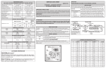
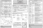
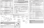
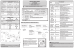
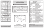
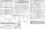
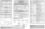
PERFORMANCE DATA
NO LOAD & NO DOOR OPENINGS AT MID-POINT CONTROL SETTING
Type A With Run/Start Capacitor
65°F (18°C) Ambient
90°F (32°C) Ambient
25 to 35%
40 to 55%
2° to 8°F (-17° to -13°C)
0° to 5°F (-18° to -15°C)
Operating Time
Freezer Temperature
SERVICE DATA SHEET
IMPORTANT
A02609401
STANDARD - AUTOMATIC DEFROST WITH LED
TOP MOUNT FREEZER - R134a
Refrigerator Temperature
35° to 40°F (2° to 4°C)
35° to 40°F (1° to 4°C)
Low Side Pressure (cut-in)
8 to 16 psig ( 55 to 110 kPa)
8 to 16 psig (55 to 110 kPa)
1 to 4 psig (7 to 28 kPa)
1 to 4 psig (7 to 28 kPa)
110 to 120 psig
(758 to 827 kPa)
150 to 175 psig
(1034 to 1207 kPa)
Wattage (last 1/3 cycle)
95 to 115
95 to 125
IMPORTANT
Amps (running)
0.9 to 1.10
0.9 to 1.20
115 vac (127 vac max)
115 vac (127 vac max)
If any green grounding wires are removed during servicing, they must be returned to their
original position and properly secured.
Low Side Pressure (cut-out)
High Side Pressure
(last 1/3 cycle)
Base Voltage
Refrigerant Charge
IMPORTANT SAFETY NOTE
The information provided herein is designed to assist qualified repair personnel only.
Untrained persons should not attempt to make repairs due to the possibility of electrical
shock. Disconnect power cord before servicing this appliance.
PLEASE RETURN THIS SHEET TO ITS ORIGINAL LOCATION.
SERVICE MODE
SERVICE MODE will step through available tests to diagnose individual electrical circuits. Fresh
Food compartment light will be OFF while in SERVICE MODE.
--> Press the door switch 3 times and hold the 4th press until 1 long
enter/exit
beep is heard. The door switch must be pressed 4 times in 2 seconds.
initiate first/next test
1
Compressor
2
Heater
3
FF Light
4
Evaporator Fan
--> Press the door switch 2 times; 2 short beeps acknowledge selection.
Press the FF door switch twice to start the first test. In each test, the
component listed will be powered on. The component will stay powered
until the next test is activated, or until 5 minutes of inactivity expire. Listen
for operating sounds; feel for heat or air flow, as appropriate, to determine
the result of each test. Press the FF door switch twice again to advance
between tests. Two beeps will sound to confirm the next test has started.
18’ = 4.25 oz. (121 g) / 20’ & 21’ = 4.75 oz. (135 g)
DEFROST SPECIFICATIONS
Safety Thermostat
Cabinet Size: 18’/20’/21’
Defrost
Thermistor
Heater
Cut-in
Cut-out
Watts
Ohms
110°F
(43.3°C)
135°F
(57.2°C)
375
35
Termination
47°F
(8.3°C)
CONDENSER FAN MOTOR
Watts
RPM
Amps
3.1
1100 CW Opposite Shaft
0.03 Running
EVAPORATOR FAN MOTOR
Watts
RPM
Amps
3.2
2600 CW
0.05 Running
ICE MAKER SPECIFICATIONS
Electrical
Thermostat
60 Hertz
Opens at 48°F (9°C)
Closes at 15°F ( -9°C) (ice maker
with black housing)
9°F (-13°C) (ice maker
with white housing)
165 vac
DOOR AJAR ALARM
Condition:
Fresh Food Door is left open for more than 5 minutes and alarm sounds.
Duration:
Alarm will sound for 2 minutes, then stop. If the “Door Ajar” condition remains,
the alarm will repeat every 30 minutes for two intervals.
Fresh Food Light:
After 15 minutes of “Door Ajar” condition, the Fresh Food light will turn off.
Reset:
Close the Fresh Food door or Press the Fresh Food Door switch.
MANUAL DEFROST
ICE MAKER CONNECTOR PLUG CONNECTIONS
Wire Number
Wire Color
Connects to:
1
Green / Yellow
Ground
2
Yellow
Water Valve
3
Black
Line
4
Light Blue
Neutral
ICE MAKER INFORMATION
Test Cycling: Remove cover by
inserting screwdriver in notch at
bottom and prying cover from housing. Use screwdriver to rotate motor gear counterclockwise until holding switch circuit is completed. All components of ice maker should
function to complete the cycle.
Water Fill Volume: The water fill adjustment screw will change the fill time. One
full turn is equal to 20cc (.68 oz.). The correct fill is 102 to 130cc (3.4 to 4.3 oz.).
When a water valve is replaced, the fill volume must be checked.
Normal Cooling
Mode
Press Door Switch 3
Times and Hold 4th Press Until
Long Beep
Service Mode
Press Door Switch
2 Times
2 Beeps
Test 1:
Test 2: Power ON
to Defrost Heater
Press Door Switch Compressor ON
To Exit Service Mode from Press Door Switch
2 Times
Enters Service
Press Door Switch any Test Press Door Switch
2 Times
2
Beeps
Mode
2 Times
3 Times and Hold 4th Press
2 Beeps
2 Beeps
Manual Defrost
Press Door Switch 5 Times to
Enter Manual Defrost. POR
or Enter Service Mode to Exit
Manual Defrost.
Test 4: Evaporator
Test 3: Fresh
Fan ON
Press Door Switch Food Light ON
2 Times
2 Beeps
P/N A01437001
Unit will complete normal defrost cycle.
enter
115 vac (127 vac max)
Heater Wattage
CAUTION
All electrical parts and wiring must be shielded from torch flame. DO NOT allow
torch to touch insulation; it will char at 200°F and flash ignite (burn) at 500°F.
Excessive heat will distort the plastic liner.
exit
--> Press the FF door switch 5 times in 2 secs.; Alarm sounds 5 short beeps
to acknowledge MANUAL DEFROST.
--> Cycle power to the unit or enter and exit
SERVICE MODE. (See SERVICE MODE)
TEMPERATURE/RESISTANCE CHART
Defrost is terminated when defrost thermistor located on the evaporator coil reaches 47°F.
Safety Thermostat in the defrost circuit is a safety device only. It will interrupt power to the defrost
heater at 135°F.
°F
-10
-9
-8
-7
-6
-5
-4
-3
-2
-1
0
1
2
3
4
5
6
7
8
9
10
FOR FRESH FOOD THERMISTOR AND DEFROST THERMISTOR
kOHMS
°F
kOHMS
°F
kOHMS
°F
83.88
11
47.25
32
27.20
53
81.56
12
46.02
33
27.04
54
79.32
13
44.84
34
26.38
55
77.15
14
43.67
35
25.75
56
75.04
15
42.55
36
25.13
57
73.02
16
41.45
37
24.53
58
71.02
17
40.39
38
23.95
59
69.08
18
39.36
39
23.38
60
67.16
19
38.36
40
22.83
61
65.34
20
37.39
41
22.29
62
63.55
21
36.44
42
21.77
63
61.82
22
35.53
43
21.26
64
60.15
23
34.63
44
20.77
65
58.20
24
33.78
45
20.29
66
56.97
25
32.94
46
19.83
67
55.43
26
32.13
47
19.37
68
53.97
27
31.33
48
18.92
69
52.53
28
30.57
49
18.49
70
51.16
29
29.83
50
18.07
71
49.81
30
29.10
51
17.66
72
48.51
31
28.39
52
17.26
73
kOHMS
16.87
16.49
16.13
16.77
15.41
15.07
14.74
14.42
14.10
13.79
13.49
13.21
12.92
12.65
12.38
12.11
11.85
11.60
11.36
11.12
10.88
I
M
C
ERF-1500
DEFROST THERMISTOR
FZC
YEL/BLK
YEL/BLK
DC SIDE
FC
SAFETY
BIMETAL
YELLOW/GREY
GREY
PIN 5
YELLOW/GREY
PIN 6
GREY
12
1
CN2
DOOR
GND
AC SIDE
CN1
7
NEUTRAL CN1
1
LAMP
FRESH FOOD LED
LT.BLUE
YEL/BLK
PIN 1
YEL/BLK
LT.BLUE
PIN 2
LT.BLUE
YEL/BLK
LT.BLUE
FRESH FOOD LED
LT.BLUE
MC6
FF DOOR SWITCH
BACK VIEW
FRONT VIEW
LT. BLUE
GREY
PIN 1
ORANGE
FF THEMISTOR
PIN 2
RED
PIN 3
MC1
NEUTRAL (RIBBED)
BLACK
GREY
SC
GROUND TO CABINET
GREY
ORANGE
PIN 2
ORANGE
RED
PIN 3
RED
11
8
LIVE (NON RIBBED)
GREEN/YELLOW
GROUND
CTRL
CN2
+5V DC
LT. BLUE
SC
MC3 MC4
MC2
RED
SLIDE
CONTROL
MC5 MC6
CFC
CC
IMWVC
PIN 3
PIN MXN
COMPRESSOR
CC
GROUND TO COMPRESSOR BASE
ERF-1500
GREEN/YELLOW
GREEN/YELLOW
RED
GRY/BLK
FF
THERMISTOR
CN2
PIN 4
GRY/BLK
9
CN2
SENSOR
PIN 2
RED
MC4
COMP
CN1
5
RED
PIN 2
RED
RED
LT. BLUE
LT. BLUE
CN4
PIN 1
RED
PIN 1
RED
PIN 2
GRY/WHT
PIN 2
GRY/WHT
MC2
FZC
2
10
CN2
LT. BLUE
DEFROST
YELLOW
MC5
PIN 1
YELLOW
PIN 4
YELLOW
PIN 5
BROWN
LT. BLUE
PIN 6
LT. BLUE
BLACK
PIN 3
BLACK
YELLOW
PIN 6
YELLOW
PIN 3
BROWN
CN5
CFC
PIN 1
PIN 2
DEFROST HEATER
IMWVC
TYCO-520935-4
ERF1500
CONDENSOR
FAN
ICEMAKER
WATER
VALVE
IMWVC
BLACK
GRY/WHT
LT. BLUE
PIN 7
LT. BLUE
PIN 4
GRY/WHT
LT. BLUE
DEFROST
THERMISTOR
GRY/WHT
+5V DC
SELECTION
LT. BLUE
CN3
RED
LT. BLUE
CN1
PIN 3
HEATER
CN1
3
BROWN
BROWN
PIN 5
BROWN
BROWN
DEFROST BIMETAL
LT.BLUE
MC1/MC3
JST-VLR-06V JST-VLP-06V
IMC
TYCO-1-480703-0
YELLOW
NEUTRAL
3
LT. BLUE
PIN 6
1
BLACK
PIN 3
CN5
LINE
LT. BLUE
BLACK
SPLICE
SPLICE
LT.BLUE
BLACK
PIN 1
PIN 9
LT. BLUE
LT. BLUE
BLACK
BLACK
GREEN/YELLOW
MC2/MC5
JST-YLR-02V
JST-YLP-02
PIN 2
PIN 4
PIN 3
ICE MAKER
PIN 1
GREEN/YELLOW
BLACK
LT. BLUE
IMC
COIL COVER GROUND
FZC
INLINE CONNECTOR ABBREVIATION KEY
ABBREVIATION
EXPLANATION
MC1
6 PIN CONNECTION LEFT OF COMPRESSOR
MC2
2 PIN CONNECTION LEFT OF COMPRESSOR
MC3
6 PIN CONNECTION RIGHT OF COMPRESSOR
MC4
6 PIN CONNECTION RIGHT OF COMPRESSOR
MC5
2 PIN CONNECTION RIGHT OF COMPRESSOR
MC6
2 PIN CONNECTION RIGHT OF COMPRESSOR
CC
CFC
IMWVC
MC4
JST-YLR-06V
JST-YLP-06
JST-VLR-09
JST-VLP-09
2 PIN CONNECTION TO ICE MAKER WATER
VALVE (GREEN)
IMC
ICE MAKER CONNECTION IN
FREEZER
FZC
FREEZER CONNECTION
FC
EVAPORATOR FAN CONNECTION IN FREEZER
SC
SLIDE CONTROL CONNECTION IN FRESH FOOD
CN1
9
RED/WHITE
PIN 1
RED/WHITE
PIN 1
MC1
RED/WHITE
RED/WHITE
GREEN/YELLOW
MC3
MC6
JST-VLR-02V
JST-VLP-02
PIN 2
PIN 5
FZC
RED/WHITE
GREEN/YELLOW
RED/WHITE
GREEN/YELLOW
PIN 1
PIN 3
FC
BLK
TYCO-1-480700-0
GROUND TO CABINATE IN
MACHINE COMPARTMENT
EVAPORATOR FAN
PIN 2
FC
TYCO-1-480701-0
FREEZER
LIGHT
SWITCH
RED/YEL
FREEZER LED
2 PIN CONNECTION TO COMPRESSOR
3 PIN CONNECTION TO CONDENSOR FAN
LT.BLUE
FAN
LT.BLUE
CFC
TYCO 1-480700-0
TYCO 1-480701-0
SC
JST XAP-03
CC
MOLEX-43335-2002
Wiring Diagram A02025501