1
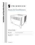
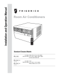
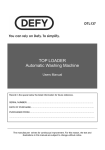
Installation and Operation Manual
Room Air Conditioners
AUTO
AUTO FAN
CONTINUOUS
88
SET POINT
ROOM TEMP
CH
ECK
FIL
T ER
AUTO SPEED
SYSTEM
F
C
AM
M
P
ON OFF
SCH
EDUL E
M
$ AR T
FAN MODE
POWER
FAN SPEED
SCHEDULE
Q Chassis Models
115-Volt: SQ05, SQ06, SQ08, SQ10
115-Volt: EQ08
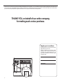
7KDQN\RXIRU\RXUGHFLVLRQWRSXUFKDVHWKH)ULHGULFK+LJK(I¿FLHQF\$LU&RQGLWLRQHU<RXUQHZ)ULHGULFKKDVEHHQFDUHIXOO\HQJLQHHUHGDQGPDQXIDFWXUHGWR
JLYH\RXPDQ\\HDUVRIGHSHQGDEOHHI¿FLHQWRSHUDWLRQPDLQWDLQLQJDFRPIRUWDEOHWHPSHUDWXUHDQGKXPLGLW\OHYHO0DQ\H[WUDIHDWXUHVKDYHEHHQEXLOWLQWR
your unit to assure quiet operation, the greatest circulation of cool, dry air, and the most economic operation.
THANK YOU, on behalf of our entire company,
for making such a wise purchase.
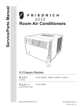
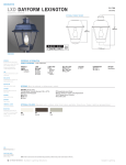
Register your air conditioner
Model information can be found on the name
plate behind the front cover.
Please complete and mail the owner
registration card furnished with this product,
or register online at www.friedrich.com. For
your future convenience, record the model
information here.
MODEL NUMBER
SERIAL NUMBER
PURCHASE DATE
FRIEDRICH
AIR CONDITIONING CO.
SAN ANTONIO, TX
MODEL NUMBER
EQ08N11-A
SERIAL NUMBER
AALY00219
VOLTS 60 HZ/ 1PH
115
103 VOLT MIN.
COOLING:
BTU/HR
7500
EER
9.8
AMPS
6.9
HEATING:
BTU/HR
4000
EER
AMPS
11.2
MAX AMPS:
23.5 OZS.
DESIGN PRESSURES
600 PSIG HS
300 PSIG LS
U.S. PATENTS
D458, 229 S
5,634,346
IF CONNECTED TO
A FUSE PROTECTED
CIRCUIT, USE A 12 A
TIME DELAY FUSE
LISTED 183H
ROOM AIR
CONDITIONER
FRIEDRICH
AIR CONDITIONING CO.
SAN ANTONIO, TX
Assembled in Mexico
MODEL NUMBER
EQ08N11-A
SERIAL NUMBER
AALY00219
VOLTS 60 HZ/ 1PH
2
Table of Contents
7DEOHRI&RQWHQWV......................................................................................................................................................................................................................................................................................3
Safety Precautions...................................................................................................................................................................................................................................................................................4
Unpacking Instructions............................................................................................................................................................................................................................................................................5
:$51,1*%HIRUH2SHUDWLQJ<RXU8QLW ..............................................................................................................................................................................................................................................6
6WDQGDUG)LOWHU&OHDQLQJ,QVWDOODWLRQ,QVWUXFWLRQV..............................................................................................................................................................................................................................7
3UHPLXP&DUERQ)LOWHU,QVWDOODWLRQ,QVWUXFWLRQV...................................................................................................................................................................................................................................7
&RQWURO3DQHO2SHUDWLRQ..........................................................................................................................................................................................................................................................................8
1HZ.KO&RQWURO2SWLRQV.......................................................................................................................................................................................................................................................................9
&RQWURO3DQHO2SHUDWLRQ,QVWUXFWLRQV..................................................................................................................................................................................................................................................10
5HPRWH&RQWURO2SHUDWLRQ....................................................................................................................................................................................................................................................................19
5HPRWH(IIHFWLYHQHVV............................................................................................................................................................................................................................................................................19
$LUÀRZ6HOHFWLRQDQG$GMXVWPHQW........................................................................................................................................................................................................................................................21
Installation Instructions...........................................................................................................................................................................................................................................................................21
Items required for installation (provided in straight cooling units only)...........................................................................................................................................................................................22
Standard Window Installation...............................................................................................................................................................................................................................................................23
&RUG5RXWLQJ&KDQJH............................................................................................................................................................................................................................................................................26
Thru-the-wall Installation .......................................................................................................................................................................................................................................................................28
)LQDO,QVSHFWLRQ6WDUWXS&KHFNOLVW..................................................................................................................................................................................................................................................30
5RXWLQH0DLQWHQDQFH.............................................................................................................................................................................................................................................................................31
6HUYLFHDQG$VVLVWDQFH.........................................................................................................................................................................................................................................................................31
$YDLODEOH$FFHVVRULHV............................................................................................................................................................................................................................................................................31
Troubleshooting Tips..............................................................................................................................................................................................................................................................................32
$GGHQGXP............................................................................................................................................................................................................................................................................................34
3
Safety Precautions
Your safety and the safety of others are very important.
We have provided many important safety messages in this manual and on your appliance. Always read and obey all
safety messages.
This is a safety Alert symbol.
This symbol alerts you to potential hazards that can kill or hurt you and others.
All safety messages will follow the safety alert symbol with the word “WARNING”
or “CAUTION”. These words mean:
WARNING
Indicates a hazard which, if not avoided, can result in severe personal injury or
death and damage to product or other property.
CAUTION
Indicates a hazard which, if not avoided, can result in personal injury and
damage to product or other property.
All safety messages will tell you what the potential hazard is, tell you how to reduce the chance of injury, and tell you
what will happen if the instructions are not followed.
NOTICE
Indicates property damage can occur if instructions are not followed.
WARNING
Refrigeration system
under high pressure
Do not puncture, heat, expose to flame or
incinerate.
Only certified refrigeration technicians should
service this equipment.
R410A systems operate at higher pressures
than R22 equipment. Appropriate safe
service and handling practices must be used.
Only use gauge sets designed for use with
R410A. Do not use standard R22 gauge sets.
4
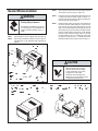
Unpacking Instructions
STEP 1.
&87$//3$&.,1*675$36
STEP 4.
6/2:/<5(029(287(5%2;
STEP 2.
&877$3($1'23(1
STEP 5.
5(029(&251(532676
STEP 3.
5(029( 723 3$&.$*,1* 0$7(5,$/ $1' &$5721
&217$,1,1*6,'(&857$,16
STEP 6.
5(029(81,7)5206+,33,1*75$<
STEP 7.
5(029( &$5%21 ),/7(5 $1' +$5':$5( )520
%2772075$<
STEP 2
STEP 1
STRAPS X3
STEP 4
STEP 3
STEP 6
STEP 7
STEP 5
5
WARNING: Before Operating Your Unit
Make sure the wiring is adequate for your unit.
If you have fuses, they should be of the time delay type. Before you install
or relocate this unit, be sure that the amperage rating of the circuit breaker
or time delay fuse does not exceed the amp rating listed in Table 1.
DO NOT use an extension cord.
Table 1.
MODEL
SQ05 SQ06
SQ08 SQ10
EQ08
CIRCUIT RATING
OR TIME DELAY
FUSE
REQUIRED WALL
RECEPTACLE
AMP
VOLT
NEMA NO.
15
125
5-15P
The cord provided will carry the proper amount of electrical power to the
unit; an extension cord may not.
WARNING
Make sure that the receptacle is compatible with the air
conditioner cord plug provided.
Electrical Shock Hazard
This insures proper grounding. If you have a two prong receptacle you
Make sure your electrical receptacle has the
same configuration as your air conditioner’s
plug. If different, consult a Licensed Electrician.
electrician. The grounded receptacle should meet all national and local
codes and ordinances. Under no circumstances should you remove the
ground prong from the plug. You must use the three prong plug furnished
with the air conditioner.
Do not use plug adapters.
Do not use an extension cord.
Do not remove ground prong.
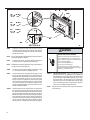
Test the power cord
All Friedrich room air conditioners are shipped from the factory with a
Leakage Current Detection Interrupter (LCDI) equipped power cord. The
LCDI device meets the UL and NEC requirements for cord connected air
conditioners effective August 2004.
Always plug into a grounded 3 prong oulet.
Failure to follow these instructions can result in
death, fire, or electrical shock.
Figure 1
To test your power supply cord:
1.
Plug power supply cord into a grounded 3 prong outlet.
2.
Press RESET (See Figure 1).
3.
Press TEST, listen for click; the RESET button trips and pops out.
4.
Press and release RESET (Listen for click; RESET button latches
and remains in). The power cord is ready for use.
RESET
TEST
WARNING:
Once plugged in, the unit will operate normally without the need to reset
the LCDI device.
If the LCDI device fails to trip when tested or if the power supply cord is
damaged, it must be replaced with a new power supply cord from the
manufacturer. Contact our Technical Assistance Line at (800) 541- 6645.
To expedite service, please have your model number available.
NOTICE
Do not use the LCDI device as an ON/OFF switch.
Failure to adhere to this precaution may cause
premature equipment malfunction.
6
TEST BEFORE EACH USE!
1. PRESS REST BUTTON.
2. PLUG LCDI INTO POWER
RECEPTACLE.
3. PRESS TEST BUTTON,
RESET BUTTON SHOULD
POP UP.
4. PRESS RESET BUTTON
FOR USE.
DO NOT USE IF ABOVE TEST
FAILS.
WHEN GREEN LIGHT IS ON.
IT IS WORKING
PROPERLY!
FRR072
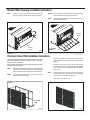
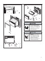
Standard Filter Cleaning / Installation Instructions
STEP 1.
6ZLQJWKHGRRURSHQDQGUHPRYHWKH¿OWHUE\JUDVSLQJWKH
¿OWHUJULSDQGSXVKLQJWKH¿OWHUKROGHUXSZDUGDQGRXWZDUG
STEP 2.
&OHDQWKHIURQWIUDPHE\ZDVKLQJWKHGLUWIURPWKH¿OWHU8VHD
PLOGVRDSVROXWLRQLIQHFHVVDU\$OORZ¿OWHUWRGU\
STEP 3.
,QVWDOOWKH¿OWHUEDFNLQWRWKHXQLW)ROORZWKH,QVWUXFWLRQVRQ
the inside of the front door.
Figure 3
Figure 2
FILTER
DOOR
FILTER
DOOR
FRR075
FILTERFRA
E
M
IN
TRU
S
TION
C
S
FRR076
Premium Carbon Filter Installation Instructions
3OHDVHIROORZWKHLQVWUXFWLRQVEHORZWRLQVWDOOWKH)ULHGULFKFDUERQ¿OWHU7KHFDUERQ
¿OWHUVKRXOGEHUHSODFHGDIWHUKRXUVRIRSHUDWLRQPRQWKVRUPRUHRIWHQLI
QHHGHGIRUPD[LPXPHIIHFWLYHQHVV
3ODFHWKHFDUERQ¿OWHURYHUWKH¿OWHUIUDPHVRWKDWWKHFDUERQ
¿OWHU¶VLQVWDOODWLRQKROHVDOLJQZLWKWKH¿OWHUIUDPHKRRNV
(Figure 4)
:KHQ\RXUHSODFHWKHFDUERQ¿OWHUFOHDQWKHZDVKDEOHPHVK¿OWHULIGLUW\$OORZ
PHVK¿OWHUWRGU\EHIRUHUHLQVHUWLQJ
6HFXUH WKH FDUERQ ¿OWHU WR WKH ¿OWHU IUDPH 0DNH VXUH WKDW
DOO¿OWHUIUDPHKRRNVDUHLQVHUWHGWKURXJKDOOLQVWDOODWLRQ
KROHVRIWKHFDUERQ¿OWHU7KHLQVWDOODWLRQKRRNVZLOOKROGWKH
¿OWHUVHFXUHO\
STEP 1.
5HPRYHWKHEODFNSODVWLF¿OWHUIUDPHIURPWKHXQLWIROORZLQJWKH
LQVWUXFWLRQVRQWKHLQVLGHRIWKH¿OWHUGRRU:DVKDEOHPHVK
¿OWHULVLQFOXGHGDQGLVSHUPDQHQWO\DWWDFKHGWR¿OWHUIUDPH
STEP 2.
/D\WKHEODFNSODVWLF¿OWHUIUDPHRQDÀDWVXUIDFHZLWKWKH
¿OWHUIUDPHKRRNVIDFLQJXSZDUG
STEP 3.
Place the black plastic filter frame with the carbon filter
installed (Figure 5) back into the front of the unit, following
WKHLQVWUXFWLRQVRQWKHLQVLGHRIWKH¿OWHUGRRU
&DUERQ¿OWHULVQRZUHDG\IRUXVH
Figure 4
Figure 5
FILTERFRA
E
M
OOK
H
)
(6
S
FRR077
FRR078
7
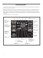
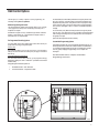
Control Panel Operation
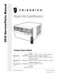
/HW¶VFKHFNRXWKRZWRFRQWURO\RXUDLUFRQGLWLRQHU2QWKHFRQWUROSDQHOMXVWDERYHWKH32:(5LVDOLTXLGFU\VWDOGLVSOD\/&'$OORIWKHFRQWUROSDQHOIXQFWLRQ
buttons and mode icons can be viewed in Figure 6.
Power On – Press the button to turn on the air conditioner. The power button illuminates to indicate that the power is on. The backlight on the power switch
ZLOODXWRPDWLFDOO\GLPWRLQWHQVLW\DIWHUVHFRQGVRILQDFWLYLW\7KHUHPRWHFRQWUROFDQDOVREHXVHGWRWXUQSRZHU212))6HH5HPRWH&RQWURO
Display ±7KHGLVSOD\LVDKLJKHI¿FLHQF\/&'ZLWKDEXLOWLQZKLWHEDFNOLJKW7KHEDFNOLJKWKDVDQDXWRPDWLFWZRVWHSGLPIXQFWLRQ$IWHUVHFRQGVRI
LQDFWLYLW\WKHGLVSOD\GLPVWRLQWHQVLW\$IWHUDQDGGLWLRQDOVHFRQGVWKHGLVSOD\VZLWFKHVRII7RXFKLQJDQ\EXWWRQDXWRPDWLFDOO\FKDQJHVWKHGLVSOD\
to full brightness.
There are three control push buttons on each side of the display.
Figure 6
COOL
HEAT
FAN
ONLY
SYSTEM:
Cycles between
HEAT, COOL or
FAN ONLY
FAN MODE:
Sets fan to either:
- Cycle automatically
- Run continuously
CONTROL MAINTENANCE
LOCKED REQUIRED
WI-FI
OPERATING (if equipped)
TEMPERATURE:
Increment UP
AUTO FAN
CONTINUOUS
88
SET POINT
ROOM TEMP
AUTO SPEED
CHECK
FILTER
WAIT
F
C
TEMPERATURE:
Increment DOWN
AM
PM
ON OFF
SCHEDULE
SCHEDULE ON
$MART
TIMER / SCHEDULE
Turns ON or OFF
FAN SPEED:
Sets fan speed:
LOW, MED, HIGH
or AUTO
(as equipped)
TIMER ON
IR WINDOW:
Do not block
ON / OFF:
Turns unit on/off
FILTER
Check / Clean
AUTO SPEED
Automatically selects
best fan cooling speed
FAN SPEED
Selected fan speed
2 DIGIT DISPLAY
Shows Setting for:
- Set Point (Temperature)
- Room Temperature
- Clock (AM/PM)
$MART OPERATING
(if equipped)
FRR079
8
Kühl Control Options
The Kühl gives you a variety of options for control, programming, and
scheduling including wireless capabilities
Wireless Programming and Control:
The new FriedrichLink™ Adapter (sold seperately) allows you to conviently
control, program and monitor your air conditioning unit remotely from a
smartphone or computer.
FriedrichLink™ Adapter accessory available through Friedrich authorized
retailers or www.friedrich.com. See FriedrichLink™ Adapter section on
www.friedrich.com for complete details.
The “Residential” (40 Hr. Work Week) Schedule has four (4) time periods: 06:00,
08:00, 18:00, and 22:00. This option will cause your Kühl Q unit to raise the room
temperature temporarily to 85°F during the hours when most people are away
at work, lower them again to 78°F prior to the time when most people will return
home, and then raise slightly to 82°F to maintain a comfortable temperature
overnight.
The “Commercial” (5-Day Business Week) Schedule has two (2) time periods:
07:00 and 18:00. This option will cause your air conditioner to raise temperatures
to 84°F after typical working hours and on weekends when commercial spaces
are typically unoccupied.
(See Control Panel Operation Instructions Section)
Pre-Programmed Scheduling Options:
Your unit’s digital control comes equipped with a 24-hour timer and two preprogrammed 7-day energy management options.
24-Hour Timer
The 24-hour timer allows you to turn the unit off and on at pre-set times by
setting an on and off time on the unit control panel. (See page 11 for details on
timer set-up.)
Pre-programmed Energy Management
Customizable Programming Options:
Customizable schedules, with up to four temperature adjustments per day, can
either be uploaded to the unit via the air conditioner’s built-in micro USB interface
or conveniently transmitted wirelessly using the new FriedrichLink™ Adapter
accessory, greatly simplifying the programming of one or multiple units.
See Figure 7.
See www.friedrich.com for complete Customizable
Programming instructions.
Your unit comes from the factory with two (2) Pre-programmed Energy
Management settings are shown in Addendum 1 (Residential & Commercial
Schedule Table).
Energy Management Schedule Options are:
1.
Residential Schedule – 40 Hr. Work Week
2.
Commercial Schedule – 5-Day Business Week
Figure 7
FRR203
9
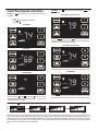
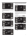
Control Panel Operation Instructions
SYSTEM - The
RIRSHUDWLRQ
SYSTEM
button allows you to sequentially select three modes
FAN MODE – The
CONTINUOUS modes.
FAN
MODE
button allows you to select between
AUTO FAN
79
TO
E
S
P IN
AUTO FAN
74
and
AUTO FAN (No Cooling Demand)
&22/
+($7 1RWDYDLODEOHRQVRPHPRGHOV
)$121/<
COOL MODE
AUTO FAN
F
T
F
FRR112
When in the AUTO FAN mode, the fan only operates when the system has
DGHPDQGWRFRRORUKHDWWKHURRP1RWHWKHIDQLVRIIQRIDQVSHHGLFRQ
indicating no command for cooling or heating.
SET POINT
AUTO FAN (Cooling Demand)
FRR103
HEAT MODE
AUTO FAN
68
74
AUTO FAN
F
F
SET POINT
SET POINT
FRR106
System has a demand for cooling. The fan is operating at a medium speed.
FRR104
FAN ONLY MODE
CONTINUOUS
CONTINUOUS
79
F
SET POINT
FRR105
:KHQLQWKH&22/ RU+($7 RU)$121/< mode, you can also
VHOHFW)$102'()$163(('7,0(56&+('8/( and . The
6<67(002'(GRHVQRWFKDQJH
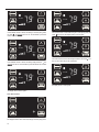
3 Speed
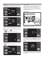
FAN SPEED - The
FAN
SPEED
FRR113
In the CONTINUOUS fan mode, the fan operates all the time. The system
SHULRGLFDOO\FRROVRUKHDWVWKHIDQ
VDLUÀRZEXWWKHÀRZRIDLUGRHVQRWVWRS
EXWWRQDOORZV\RXWRWRJJOHEHWZHHQIRXUPRGHVRIRSHUDWLRQ/2:0(',80+,*+DQG$872
AUTO
FRR095
:KHQIDQVSHHG$872PRGH6<67(0PRGH&22/RU+($7LVVHOHFWHGIDQVSHHGDXWRPDWLFDOO\YDULHVGHSHQGLQJRQWKHGLIIHUHQFHEHWZHHQWKHXQLW
V
VHWSRLQWRQWKHFRQWUROSDQHODQGWKHDFWXDOURRPWHPSHUDWXUH/HWPHH[SODLQ6D\IRUH[DPSOH\RX¶UHZRUNLQJLQ\RXUJDUDJHDQG\RXRSHQWKHELJGRRUIRU
several minutes. The system will sense a wide difference between the set point and the actual room temperature. When this occurs, the system fan speed
LQFUHDVHVWR+,*+IRUDSHULRGRIWLPH7KHIDQVSHHGGHFUHDVHVLQVWHSDVWKHWHPSHUDWXUHGLIIHUHQFHGHFUHDVHV:KHQWKHURRPWHPSHUDWXUHPDWFKHVWKH
system's set point, fan speed returns to the original setting.
UP and DOWN
- arrows - Pressing either
or button changes
the system's set point (desired room temperature). These buttons are also
used to make system parameter changes latter in this manual.
AUTO FAN
74
The icon illuminates.
7KH7,0(5IXQFWLRQRSWLRQV\VWHPGHIDXOWDOORZV\RXWRGH¿QHDGDLO\
V\VWHP21DQG2))WLPHZLQGRZ)RUH[DPSOH\RXFDQFRPPDQGWKH
V\VWHPWRWXUQ21DWDPDQGWXUQ2))DWSPHYHU\GD\
7KH6&+('8/(IXQFWLRQDOORZV\RXWRFKRRVHHLWKHU5HVLGHQWLDORSWLRQ
RU&RPPHUFLDORSWLRQ7KH5HVLGHQWLDODQG&RPPHUFLDORSWLRQVDUH
described latter in this manual.
F
OTHER FUNCTIONS
Figure 8
SET POINT
FRR100
AUTO FAN
75
F
FRIE
RIC
D
IRC
A
.
G
IT
D
N
O
N
A
S
SET POINT
T
N
A
I,
N
O
H
X
T
FRR0
7
9
FRR101
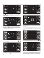
2QHSUHVVHTXDOVGHJUHHRIFKDQJH+ROGLQJWKHEXWWRQGRZQIRUPRUH
WKDQVHFRQGVVWDUWVWKHIDVWLQFUHPHQWGHFUHPHQWFKDQJHRIWKHVHW
point.
TIMER SCHEDULE - The
or SCHEDULE function.
The
EXWWRQDOORZV\RXWRVHOHFWWKH7,0(5
EXWWRQVHOHFWHGGXULQJDGH¿QHG2))ZLQGRZ
SET TIME7RDGMXVWWKHXQLW
VWLPHSUHVVDQGKROGWKH+285DQGWKH0,1
EXWWRQVIRUWKUHHVHFRQGV5HIHUWR)LJXUH
11
AM
FRR128
The unit's current hour displays. Use the
or EXWWRQVWRDGMXVWWKH
KRXU7RFKDQJHIURP$0WR30FRQWLQXHWRLQFUHPHQWUROOWKHGLVSOD\
3UHVV7,0(56(75HIHUWR)LJXUHEXWWRQWRGLVSOD\WKHXQLW
VFXUUHQW
minutes.
FRR122
The
The
icon illuminates.
25
EXWWRQVHOHFWHGGXULQJDGH¿QHG21ZLQGRZ
AUTO FAN
79
F
FRR129
SET POINT
Use the
or EXWWRQVWRDGMXVWWKHPLQXWHV7KHFORFNLVQRZVHW
IRU$03UHVV7,0(56(75HIHUWR)LJXUHEXWWRQWRGLVSOD\WKH
unit's day setting.
FRR123
4
C
FRR130
Use the
or EXWWRQVWRDGMXVWWKHGD\WR7KHGD\VHWWLQJLVXS
to the you the user. If you set the current day = 1, and today is Tuesday,
WKHQ'D\ 7XHVGD\
AUTO FAN
79
FRR134
$³&´ZLOOÀDVKIRUVHFRQGVDQGWKHQUHYHUWWRDQRUPDOGLVSOD\
AUTO FAN
F
26
C
SET POINT
SET POINT
FRR135
FRR131
3UHVV7,0(56(75HIHUWR)LJXUHEXWWRQWRH[LWDQGVDYHWKH6(7
7,0(IXQFWLRQ7KH7,0(56(7EXWWRQPXVWEHSUHVVHGZLWKLQVHFRQG
%XWWRQLQDFWLYLW\IRUPRUHWKDQVHFRQGVFDXVHVWKHGLVSOD\WRWLPHRXW
and return to the normal operating display.
7KH)LFRQJRHVDZD\DQGWKH&LFRQLOOXPLQDWHVRQWKHQRUPDOGLVSOD\
DIM Function
7KHUHDUHWKUHHVHSDUDWHGLVSOD\EULJKWQHVVOHYHOV$872DQGIXOO
7R FKDQJH WKH ',0 VHWWLQJ SUHVV WKH 3RZHU EXWWRQ IRU WKUHH
seconds.
ºF - ºC Select
AUTO FAN
79
1
F
SET POINT
FRR192
FRR132
7RVZLWFKIURPGHJUHHV)DKUHQKHLW)WR&HOVLXV&SUHVV
buttons for three seconds.
or
or
2
f
FRR133
$³)´ZLOOÀDVKIRUVHFRQGVDQGWKHQUHYHUWWRDQRUPDOGLVSOD\7RFKDQJH
IURP)WR&SUHVVWKH
or
button within 5 seconds.
7KHLQGLFDWHVD',0VHWWLQJRI$XWRIDFWRU\GHIDXOW8VHWKH
buttons to change the setting.
FRR193
7KHLQGLFDWHVD',0VHWWLQJRI3UHVVWKH7,0(56(7EXWWRQZLWKLQ
VHFRQGVWRVDYHWKHVHWWLQJ%XWWRQLQDFWLYLW\IRUPRUHWKDQVHFRQGV
causes the display to time out and return to the normal operating display.
This means there is a compressor demand but the system is not ready
IRUWKHFRPSUHVVRUWRRSHUDWH)RUH[DPSOHDVKRUWSRZHURXWDJHWKH
compressor will not restart until the internal pressures of the compressor
are at the proper level.
3
F
FRR194
7KHLQGLFDWHVD',0VHWWLQJRIIXOOEULJKWQHVV3UHVVWKH7,0(5
6(7 5HIHU WR )LJXUH EXWWRQ ZLWKLQ VHFRQGV WR VDYH WKH VHWWLQJ
%XWWRQLQDFWLYLW\IRUPRUHWKDQVHFRQGVFDXVHVWKHGLVSOD\WRWLPHRXW
and return to the normal operating display.
Alerts
:KHQWKH¿OWHUQHHGVWREHFOHDQHGRUUHSODFHGWKH CHECK
FILTER icon displays.
AUTO FAN
79
FRR179
,IWKHURRPIUHH]HSURWHFWLRQLVDFWLYHWKHGLVSOD\LQGLFDWHVWKLVE\VKRZLQJ
)´2QFHWKHFRQGLWLRQLVVDWLV¿HGWKH³)´GLVSOD\LVUHPRYHG3UHVV7,0(5
6(7)LJXUHEXWWRQRYHUULGHVWKHIUHH]HSURWHFWLRQDOHUWIRUPLQXWHV
This alert appears when the room is too cold for the air conditioner to
RSHUDWHSURSHUO\$QRWKHUFDXVHRIDOHUWRFFXUVZKHQWRPXFKLFHEXLOGV
up on the unit's condenser.
Lock Control Panel
F
FAN
To lock the front panel controls, press and hold the SPEED +
buttons
for 3 seconds. The lock icon
illuminates to indicate the locked status.
SET POINT
FILTER
FRR118
The alert can be dismissed by pressing the
FAN
MODE
and
When maintenance is required, a service icon
AUTO FAN
79
AUTO FAN
for 3 seconds.
appears on screen.
79
F
SET POINT
FRR116
F
To unlock, presses and hold the
FAN
SPEED
+
buttons for 3 seconds.
SET POINT
AUTO FAN
FRR119
This ZLOOUHPDLQRQWKHGLVSOD\XQWLOWKHIDXOWKDVEHHQFRUUHFWHG1RWH
the LFRQZLOOÀDVKLIWKHIDXOWLVRIDPRUHVHYHULW\QDWXUH
The wait icon
79
F
SET POINT
illuminates when the compressor lockout is active.
FRR117
AUTO FAN
79
The lock icon
disappears to indicate unlocked status.
F
SET POINT
FRR120
External Control Status
3.
The $MART icon illuminates to indicate that the system is being controlled
remotely.
AUTO A
F N
79
TP
E
S
IN
O
Commercial Schedule - When selected the unit follows a preprogrammed set of operational parameters that covers 7 days of
the week with 2 time windows during each day. Each time window
KDVLW
VRZQVHWRIRSHUDWLQJSDUDPHWHUV5HIHUWR$GGHQGXP
7RPDNHDFKDQJHWRWKHWLPHZLQGRZVUHIHUWR$GYDQFHG
Programming section of this manual.
F
1
T
$MART
SCHEDULE
FRR125
FRR137
AUTO FAN
79
To change the
button for 3 sec.
F
VHOHFWLRQSUHVVDQGKROGWKH7,0(56&+('8/(
If the Schedule function is available, the system displays the icon +
SCHEDULE icon. The display indicates the schedule function that is active.
To change to an alternate schedule (2 or 3), press the
or
button.
If the Schedule function is not available, the Timer icon shows without
the SCHEDULE icon.
SET POINT
7RVDYHDQGH[LWWKLVVHOHFWLRQSUHVVWKH7,0(56(7EXWWRQ)LJXUH
FRR126
The
icon illuminates to indicate that the system is receiving a Wi-Fi
connection.
If there is no button activity for 15 seconds, the function will time out and
OHDYHWKHRULJLQDOVHOHFWLRQ2QFHWKHVHOHFWLRQLVVDYHGRUWLPHGRXWWKH
display reverts to the normal display.
ADVANCED FUNCTIONS
/HWPHSXWLQSODLQZRUGVPDQ\RI\RXUXQLW
VDGYDQFHGIXQFWLRQV7LPHU
Schedule, Error Mode, Test Mode, and Maintenance Menu). The functions
mentioned in the following section may or may not be available depending
on the air conditioner model.
2
Timer/Schedule Select
AUTO FAN
SCHEDULE
79
FRR138
F
$IWHUSUHVVLQJWKH
or
button, within 15 second of pressing the
EXWWRQIRUVHFRQGVWKHGLVSOD\LQGLFDWHVDFKDQJHWR7LPHU6FKHGXOHU
7RVDYHDQGH[LWWKLVVHOHFWLRQSUHVVWKH7,0(56(7EXWWRQ)LJXUH
SET POINT
FRR136
7KHFRQWUROV\VWHPKDVWKUHH7LPHU6FKHGXOHIXQFWLRQV
1.
2.
Timer (factory default) $OORZV\RXWRFRPPDQGWKHXQLWWRWXUQ
21DQG2))DWWLPH\RXSURJUDPZLWKLQDGD\ZLQGRZ6HWWLQJ
the start, stop and day window can be found latter in this manual.
Residential Schedule - When selected the unit follows a preprogrammed set of operational parameters that covers 7 days of
the week with 4 time windows during each day. Each time window
KDVLW
VRZQVHWRIRSHUDWLQJSDUDPHWHUV5HIHUWR$GGHQGXP
7RPDNHDFKDQJHWRWKHWLPHZLQGRZVUHIHUWR$GYDQFHG
Programming section of this manual.
AUTO FAN
79
F
SET POINT
FRR136
The display reverts to the normal display.
AUTO FAN
79
F
SET POINT
FRR139
1RZWKHQH[WWLPHWKH
button is pressed the system operates in the
mode (1, 2 or 3) you programmed.
FRR143
The display returns to normal once the settings are saved.
Timer Stop Time
Modify the TIMER Function
Timer Start Time
AUTO FAN
79
AUTO FAN
F
79
F
SET POINT
SET POINT
FRR144
FRR140
7KHGLVSOD\VKRZVDQRUPDOV\VWHP3UHVVDQGKROGWKH+285EXWWRQ
)LJXUHIRUVHFRQGV1RWHWKH7LPHUVWDUWVWRSWLPHVPD\EHVHWHYHQ
when the system is in the Schedule mode.
4
7KHGLVSOD\VKRZVDQRUPDOV\VWHP3UHVVDQGKROGWKH0,1EXWWRQ)LJXUH
IRUVHFRQGV1RWHWKH7LPHUVWDUWVWRSWLPHVPD\EHVHWHYHQZKHQ
the system is in the Schedule mode.
11
AM
AM
OFF
ON
FRR145
FRR141
Use the
or EXWWRQWRDGMXVWWKHKRXU3UHVVWKH7,0(56(7EXWWRQ
)LJXUHWRDGMXVWWKHPLQXWHV
Use the
or EXWWRQWRDGMXVWWKHKRXU3UHVVWKH7,0(56(7EXWWRQ
)LJXUHWRDGMXVWWKHPLQXWHV
55
21
OFF
ON
FRR146
FRR142
Use the
or EXWWRQWRDGMXVWWKHPLQXWHV3UHVVWKH7,0(56(7
EXWWRQ)LJXUHZLWKLQVHFRQGVWRH[LWDQGVDYHWKHVHWWLQJ7KHWLPHU
LVQRZVHWWRVWDUWDW$0
Use the
or EXWWRQWRDGMXVWWKHPLQXWHV3UHVVWKH7,0(56(7
EXWWRQ)LJXUHZLWKLQVHFRQGVWRH[LWDQGVDYHWKHVHWWLQJ7KHWLPHU
LVQRZVHWWRVWRSDW$0
AUTO FAN
79
F
AUTO FAN
SET POINT
79
SET POINT
F
SCHEDULE
FRR147
The display returns to normal once the settings are saved.
Timer - Scheduler Control Block
AUTO FAN
79
SET POINT
FRR151
The Timer LFRQVWRSVEOLQNLQJDIWHUVHFRQGV<RXPXVWWXUQWKHDFWLYH
7LPHURU6FKHGXOHPRGH2))EHIRUHPDNLQJFKDQJHV2QFHWKHFKDQJHV
are made, press the
button to re-activate Timer or Schedule mode.
F
AUTO FAN
SCHEDULE
79
F
SET POINT
FRR148
,IWKHXQLWLVRSHUDWLQJLQWKH7,0(5RU6&+('8/(PRGHDQGWKHQ\RX
SUHVVDQ\EXWWRQH[FHSWWKH
button, the Timer
icon begins to
EOLQN$OOEXWWRQDFWLRQLVEORFNHG
AUTO FAN
79
SET POINT
FRR152
Schedule ON Scenarios
F
SCHEDULE
SCHEDULE
FRR153
FRR149
The Timer LFRQVWRSVEOLQNLQJDIWHUVHFRQGV<RXPXVWWXUQWKHDFWLYH
7LPHURU6FKHGXOHPRGH2))EHIRUHPDNLQJFKDQJHV2QFHWKHFKDQJHV
are made, press the
button to re-activate Timer or Schedule mode.
The display shows a normal system.
,IWKH6FKHGXOHIXQFWLRQLVWXUQHG21GXULQJQRUPDORSHUDWLRQWKH SCHEDULE
and Timer
icons illuminates. The control system immediately runs the
current period schedule parameters.
,IWKHXQLWLVRSHUDWLQJLQWKH7,0(5RU6&+('8/(PRGHDQGWKHQ\RX
button, the Timer icon begins to blink.
SUHVVDQ\EXWWRQH[FHSWWKH
AUTO FAN
79
AUTO FAN
F
79
F
SET POINT
SET POINT
FRR154
The display shows a normal system.
FRR150
$OOEXWWRQDFWLRQLVEORFNHG
AUTO FAN
79
SET POINT
F
AUTO FAN
79
F
SET POINT
SCHEDULE
FRR159
FRR155
,IWKH6FKHGXOHIXQFWLRQLVWXUQHG21GXULQJD6NLSSHULRGWKH SCHEDULE
and Timer
icons illuminates. The control system immediately runs the
previous (non-skip) period schedule parameters.
,IWKH7LPHUIXQFWLRQLVWXUQHG21GXULQJWKH21WLPHWKH7LPHU
illuminates. The control system continues to run.
icon
Scheduler OFF Scenarios
Timer ON Scenarios
AUTO FAN
79
F
AUTO FAN
79
SET POINT
SET POINT
F
SCHEDULE
FRR160
FRR156
The display shows a normal system.
The display shows the unit in Schedule mode.
AUTO FAN
79
F
SET POINT
FRR161
FRR157
,I WKH 7LPHU IXQFWLRQ LV WXUQHG 21 GXULQJ WKH 2II WLPH WKH
icon
LOOXPLQDWHV7KHFRQWUROV\VWHPLPPHGLDWHO\WXUQVWKHXQLW2))
AUTO FAN
79
,IWKH6FKHGXOHIXQFWLRQLVWXUQHG2))GXULQJDQDFWLYHVWDWHQRWRIIWKH
Timer and SCHEDULE icons turn off. The control stays in the current state.
The display shows a normal system.
F
SET POINT
SCHEDULE
FRR158
The display shows a normal system.
FRR162
7KHGLVSOD\VKRZVWKHXQLWLQ6FKHGXOHPRGHGXULQJDQLQDFWLYH2))
period.
AUTO FAN
79
F
AUTO FAN
SET POINT
79
F
SET POINT
FRR163
,IWKH6FKHGXOHIXQFWLRQLVWXUQHG2))GXULQJDQLQDFWLYH2))SHULRG
the Timer
and SCHEDULE icons turn off. The unit wakes up in the last
known non-schedule state.
AUTO FAN
79
SET POINT
FRR167
,IWKH7LPHUIXQFWLRQLVWXUQHG2))GXULQJDQLQDFWLYH2))SHULRGWKH
Timer icon turns off. The display shows a normal system.
AUTO FAN
F
79
F
SET POINT
SCHEDULE
FRR168
FRR164
,IWKH7LPHUIXQFWLRQLVWXUQHG2))GXULQJWKH21WLPH7KH7LPHU
turns off. The control stays in the current state.
icon
,IWKH6FKHGXOHIXQFWLRQLVWXUQHG2))GXULQJD6NLSSHULRGWKH and
SCHEDULE icons turn off. The unit wakes up in the last known non-schedule
state.
AUTO FAN
AUTO FAN
79
79
F
SET POINT
F
SET POINT
FRR169
The display shows a normal system.
FRR165
The display shows a normal system.
Timer OFF Scenarios
FRR166
7KHGLVSOD\VKRZVWKHXQLWLQ7LPHUPRGHGXULQJDQLQDFWLYH2))SHULRG
FAN SPEED Button - Used to sequentially select new fan speed, plus
FAN
button is pressed, the fan speed icon
$872RSHUDWLRQ:KHQWKH SPEED
(triangle) changes to indicate the new speed level. Fan speed automatically
varies depending on the set temperature on the control panel and the actual
URRPWHPSHUDWXUH)RUH[DPSOHLIWKHUHLVDELJGLIIHUHQFHEHWZHHQ\RXU
set temperature and the actual room temperature, the system fan speed
LQFUHDVHVWR+,*+,WUHPDLQVDWWKLVVSHHGXQWLOWKHURRPWHPSHUDWXUH
matches the set temperature.
Remote Control Operation
Remote Control5HIHUWR)LJXUHVDQGGXULQJRSHUDWLRQGHVFULSWLRQ
Getting Started,QVWDOOWZR$$$EDWWHULHVLQWKHEDWWHU\FRPSDUWPHQW
located on the back of the unit.
Operation - The remote control should be within 25 feet of the air
FRQGLWLRQHUIRURSHUDWLRQ5HIHUWR)LJXUHIRUHIIHFWLYHQHVV3UHVVWKH
power button to turn the remote on. The remote will automatically power
off after 15 seconds if the buttons are not being pressed. The remote must
be on to control the unit.
SCHEDULE Button – The SCHEDULE
button turns the schedule function
on and off. Press the Schedule button once to turn on the Schedule
5HVLGHQWLDO&RPPHUFLDO7LPHURU&XVWRPL]HGWKDWKDVDOUHDG\EHHQ
selected on your unit. Pressing the SCHEDULE
button a second time turns
the schedule function off.
POWER Button - Turns remote and unit on and off.
SYSTEM Button $OORZV WKH XVHU WR VHTXHQWLDOO\ VHOHFW &RRO ,
+($7 DQG)$121/< operation. When the button is pressed, the
display indicates which mode has been selected via a display message.
1RWH WKDW ZKHQ WKH KHDWLQJ IXQFWLRQ LV QRW DYDLODEOH WKH V\VWHP ZLOO
DXWRPDWLFDOO\VNLSWKH+($7PRGH
UP and DOWN Arrows - Pressing either the
(UP) or
'2:1
button changes the desired room temperature. The factory preset lower
and upper limits are 60)&DQG)&7KHVHEXWWRQVDUHDOVR
used to navigate between function options when using the User Menu or
Maintenance Mode.
FAN MODE Button - Selects between automatic ( AUTO FAN ) or CONTINUOUS
operation. In the AUTO FAN mode, the fan only turns on and off when the
compressor operates or the heat function is enabled.
NOTE:
Remote Effectiveness
Hand Held Remote - Has an operating range of up to 25 ft. The infrared
remote control signal must have a clear path to transmit the command to
the air conditioning unit. The remote signal has some ability to "bounce"
off of walls and furniture similar to a television remote control. The diagram
below shows the typical operating range of the control in a standard room
with 8 ft high ceilings.
LVQRWDYDLODEOHLQWKH)$121/<0RGHWKHGLVSOD\
indicates CONTINUOUS . In the CONTINUOUS mode, fan speed is
FAN
determined by your selection on the SPEED
button.
AUTO FAN
Figure 9
TOP VIEW
25ft
25ft
7.5ft
SIDE VIEW
4ft
45°
60°
60°
6ft
30°
60°
8ft
45°
45°
25ft
60°
30°
45°
30°
30°
16ft
8ft
25ft
25ft
25ft
25ft
25ft
FRR080
Figure 10
AUTO FAN
CONTINUOUS
AUTO
88
DISPLAY
C F
SYSTEM
FAN MODE
SYSTEM
FAN MODE
POWER
TEMPERATURE
UP
POWER
FAN SPEED
TEMPERATURE
DOWN
SCHEDULE
SCHEDULE
FAN SPEED
FRR081
Figure 11
COOL
ICON
SYSTEM
MODE
FAN
MODE
FAN
SPEED
AUTO FAN
CONTINUOUS
AUTO
HEAT
ICON
FAN ONLY
ICON
88
C F
°F / °C
ICONs
SCHEDULE
ICON
FRR082
20
$LUÁRZ6HOHFWLRQDQG$GMXVWPHQW
$LUÁRZGLUHFWLRQDGMXVWPHQW
Figure 12
LEFT AIRFLOW
LEVER
RIGHT AIRFLOW
LEVER
7KHDLUÀRZSDWKPD\EHDGMXVWHGWRGLVWULEXWHDLULQGHSHQGHQWO\IURPWKH
left or right side of the discharge opening. Each of the banks of louvers
can be directed left, right, up or down in order to achieve the most optimum
DLUÀRZSRVLWLRQLQJ
7RDGMXVWDLUÀRZGLUHFWLRQJUDEWKHOHYHULQWKHFHQWHURIWKHORXYHUEDQNDQG
move it in the direction that you would like the air to be directed. Please
QRWHWKDWLWLVQRUPDOWKDWDLUÀRZPD\EHVWURQJHURXWRIRQHVLGHRIWKH
louvers than the other.
FRR083
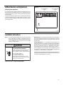
Installation Instructions
NOTE:
This section includes installation instructions for window mount
DQG WKUXWKHZDOO PRXQW PHWKRGV .DO KHDWFRRO XQLWV DUH
designed for permanent thru-the-wall installation. Mounting the
unit in a window will require a window accessory kit, available
through your Friedrich dealer.
WARNING
Electrical Shock Hazard
Make sure your electrical receptacle has the
same configuration as your air conditioner’s
plug. If different, consult a Licensed Electrician.
Do not use plug adapters.
Do not use an extension cord.
Do not remove ground prong.
IMPORTANT:%HIRUH\RXEHJLQWKHDFWXDOLQVWDOODWLRQRIWKHDLUFRQGLWLRQHU
EHVXUH\RXUHOHFWULFDOUHTXLUHPHQWVDUHDVGHVFULEHGEHORZ&RQVXOWDQ
electrical professional as necessary to insure home wiring is per local
electrical codes.
CIRCUIT PROTECTION ± $Q RYHUORDGHG FLUFXLW ZLOO LQYDULDEO\ FDXVH
malfunction or failure of an air conditioner, therefore, it is necessary that the
HOHFWULFDOSURWHFWLRQLVDGHTXDWH'XHWRPRPHQWDU\KLJKFXUUHQWGHPDQG
ZKHQ\RXUDLUFRQGLWLRQHULVVWDUWHGXVHD7,0('(/$<IXVHRUD+$&5
W\SHFLUFXLWEUHDNHU&RQVXOW\RXUGHDOHURUSRZHUFRPSDQ\LILQGRXEW
<RXUDLUFRQGLWLRQHUPXVWEHFRQQHFWHGWRDSRZHUVXSSO\ZLWKWKHVDPH
$&YROWDJHDQGKHUW]DVPDUNHGRQWKHXQLWQDPHSODWH2QO\DOWHUQDWLQJ
FXUUHQW$&QRGLUHFWFXUUHQW'&FDQEHXVHG
The power cord has a plug with a grounding prong of approved type and a
PDWFKLQJSOXJUHFHSWDFOHZLWKJURXQGLVUHTXLUHG5HIHUWRSDJHIRUWKH
correct type of plug receptacle for your model.
Always plug into a grounded 3 prong oulet.
Failure to follow these instructions can result in
death, fire, or electrical shock.
READ THIS FIRST! Electrical Requirements
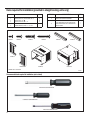
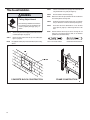
Items required for installation (provided in straight cooling units only)
ITEM NO
QTY.
ITEM NO
1
2
3
4
SCREW, SHEET METAL, #8 x "
SCREW, PHILLIPS, TRUSS HEAD, #8 x ½"
SCREW, HEX, #8 x "
SCREW, PHILLIPS, #8 x 1 ¼"
8
4
10
2
7
8
LEFT SIDE CURTAIN ASSEMBLY
RIGHT SIDE CURTAIN ASSEMBLY
1
1
9
5
6
GRAY GASKET, FOAM, 1" x 1 ½" x 42"
WHITE GASKET, FOAM, 1" x 1 ½" x 48"
1
1
10
CABINET OR SLEEVE w/ TOP ANGLE BAR
(TOP ANGLE BAR NOT INCLUDED ON EQ)
AIR CONDITIONING UNIT w/ DECORATIVE
FRONT PANEL
1
1
1
ITEM #1
DESCRIPTION
ITEM #2
ITEM #3
ITEM #4
DESCRIPTION
ITEM #5
QTY.
ITEM #6
ITEM #7
ITEM #8
ITEM #10
ITEM #9
ITEMS NOT TO SCALE
FRR084
Recommended tools required for installation: (not included)
HEXHEAD SCREWDRIVER
COMMON SCREWDRIVER
PHILLIPS SCREWDRIVER
22
Standard Window Installation
WARNING
STEP 3.
&HQWHUFDELQHWLQZLQGRZZLWKVLOOFKDQQHOSRVLWLRQHGDJDLQVW
ZLQGRZVWRRODVVKRZQLQ)LJXUH6HFWLRQ$$
STEP 4.
3XOOZLQGRZVDVKGRZQEHKLQG6KHOO6XSSRUW&KDQQHORQWRS
RIFDELQHWWKLVKHOSVKROGFDELQHWLQSODFH,QVWDOO1R[
KH[KHDGVFUHZLWHPSDJHLQVLOOFKDQQHODWERWWRPRI
window opening as shown in Figure 15.
STEP 5.
([WHQGWKHVOLGLQJFXUWDLQVRQHDFKVLGHVRWKHIUDPHV¿WLQWR
the window channels. While holding the curtain frames in
place, mark four (4) hole locations (hole locations are in the
upper corners on left and right curtain assembly), two (2) in the
ZLQGRZMDPEDQGWZRLQWKHZLQGRZVDVK6OLSWKHFXUWDLQV
EDFNIURPPDUNHGORFDWLRQVDQGGULOOIRXUGLDPHWHU
SLORWKROHV$JDLQH[WHQGWKHVOLGLQJFXUWDLQVRQHDFKVLGH
DQGWKHQLQVWDOOWZR1R[ò3KLOOLSVKHDGVFUHZVLWHP
SDJHDQGWZR1R[ó3KLOOLSVKHDGVFUHZV
LWHPWKURXJKWKHFXUWDLQIUDPHVDVVKRZQLQ)LJXUH
Falling Object Hazard
Not following Installation Instructions
for mounting your air conditioner can
result in property damage, injury, or
death.
STEP 1.
$IWHUUHPRYLQJWKHXQLWIURPVKLSSLQJFDUWRQ6HH)LJXUH
STEP 2.
$WWDFKFXUWDLQDVVHPEOLHVWRFDELQHWDVVKRZQLQ)LJXUH
8VHHLJKW1R[VORWWHGKH[KHDGVFUHZVLWHP
page 22).
Figure 13
L
E
H
S
R
O
P
U
S
T
AN
H
C
L
E
C TAIN
R
U
AS
L
B
M
E
S
Y
T AIN
E
R
IG
AC
R
B
T
E
K
R
U
C
AS
L
B
M
E
S
W
E
R
C
S
8
#x/8
”3L
D
E
T
O
SE
X
HE
A
HD
(
A
R
T
S
U
IL
8E
D4
IR
U
Q
(A
EC
HID
).SIN
E
T
S
FR
M
O
EL
ID
S
N
V
E
S
AS
L
B
M
E
S
CAUTION
TAIN
Y
FT
E
(L
)
NO
IO
T
NP
AG
E2
, IT
M
E
)
1
#
AL
L
TAIN
.
O
T C
R
U
YR
T
E
Cut/Sever
Although great care has been
taken to minimize sharp edges
in the construction of your unit,
use gloves or other hand
protection when handling unit
Failure to do so can result in minor
to moderate personal injury.
AIN
IGB
AC
R
T
E
K
R TAIN
U
C
AS
L
B
M
E
S
Y
)
T
H
IG
(R
FR
5
8
0
R
Figure 14
O
T P
L
U
IT
N
U
FR
M
O
,U
V
E
L
S
E
S
A
C
O
L
DN
E
T
O
RID
E
H
IT
E
SF
O
FR
T
N
O
.O
T AIN AS
B
IT
S
O
T H
DL
L
O
V
E
SH
E
IL
W
G
IN
L
U
PN
IT
U
AK
M
EU
E
R
S
AIRO
CISO
R
E
IT
D
N
NFIR
M
R
O
P
U
S
FO
E
B
EE
R
G
IN
V
O
M
RN
IT
U
ES
H
T
EH
ID
AD
S
E
L
N
E
H
TU
IT
N
AN
EO
C
RH
P
L
E
D
A
R
O
C
E
ASN
AR
S
C
E
FR
M
O
S
.
V
E
L
E
IV
T
Y
W
N
E
H
AR
C
RH
O
P
L
E
AS
(B
P
E
GO
IN
Y
RH
AN
IGU
L
D
IT
N
ASN
AR
S
C
E
YO
T
AN
), M
AIN
T
AIN
IGC
AR
E
L
AC
E
NFR
M
O
R
O
P
U
S
,O
T AIN AS
B
IT
S
TN
IT
U
FR
M
O
T
O
B
AL
L O
T
S
B
AN
E
C
O
T M
AC
.
S
E
L
T
FR
M
O
.
V
E
L
S
EH
ID
S
AN
E
L
D
FR
6
8
0
R
23
Figure 15
ELL
H
S
S
R
O
P
U
TC
AN
H
EL
IN
W
DO
W
AS
S
H
SW
E
R
C
,1
”H
/2
IPLLIP
SH
EAD
EE ILLU
(S
A
R
T
S
IO
T
,
N
IT
EM #
,P
2
AG
E2
)
SW
E
R
C
, 11
”P
/4
ILLIP
H
SE
HAD
EE ILLU
(S
A
R
T
S
ITO
,
N
IT
EM #
,P
4
AG
E2
)
A
SW
E
R
C
,8
#x 7
”H
/8
EXH
EAD
EE ILLU
(S
A
R
T
S
IO
T
,
N
IT
EM #
3, P AG
E2
)
A
AB
C
IE
NT
ILL
S
AN
H
C
EL
IN
W
DO
W
T
S
L
O
SECTION A-A
STEP 6.
FR
7
8
0
R
Inspect the unit before inserting it into the sleeve. The fan
VKRXOGEHPDQXDOO\URWDWHGWRLQVXUHWKDWWKH\WXUQIUHHO\%H
sure the electrical cord will be out of the way when inserting
the unit into the sleeve.
WARNING
Electrical Shock Hazard
NOTE: )RU\RXUVDIHW\'2127SOXJWKHHOHFWULFDOFRUGLQWRDQHOHFWULFDO
outlet until installation is complete.
STEP 7.
Make sure your electrical receptacle has the
same configuration as your air conditioner’s
plug. If different, consult a Licensed Electrician.
,IWKHXQLWFKHFNVRXW2.LWLVUHDG\WREHSODFHGLQWRSRVLWLRQ
on bottom rails of the cabinet and pushed into place.
Do not use plug adapters.
Do not use an extension cord.
Do not remove ground prong.
NOTE: 'RDOOOLIWLQJRIWKHXQLWE\WKHERWWRPSDQRQO\DQGZLWKDVVLVWDQFH
or help as necessary (See Figure 14).
STEP 8.
The chassis must be pulled out slightly, so that there is a gap
RIEHWZHHQWKHXQLWDQGVKHOO6HH)LJXUH
STEP 9.
,QVWDOOWKHZKLWHFKDVVLVVHDOJDVNHWLWHPSDJHDQG
WKHJUD\ZLQGRZ VHDO JDVNHW LWHP &DUHIXOO\ LQVHUWWKH
ZKLWHJDVNHWLWHPEHWZHHQWKHFKDVVLVDQGWKHFDELQHW
starting at either bottom corner and go up the side, across
the top and down the opposite side. Insert the gray gasket
LWHP EHWZHHQ WKH ZLQGRZ VDVKHV DV VKRZQ LQ )LJXUH
16. If chassis seal gasket is not installed, the operation of the
XQLWZLOOEHQHJDWLYHO\DIIHFWHG$OVRWKHRSHUDWLRQQRLVHDQG
RXWVLGHQRLVHZLOOEHDPSOL¿HG
STEP 10.
Hold the decorative front as shown in Figure 17. Insert the two
WDEVRIWKH'HFRUDWLYH)URQW3DQHOLQWRWKHVORWVLQWKHWRSRI
the cabinet and lower the bottom of the decorative front to the
ERWWRPRIWKHFDELQHW5RXWHWKHHOHFWULFDOFRUGWRWKHULJKWRU
left side of the bottom of the cabinet as required by the location
of the electrical wall outlet. Use the notches provided at the
ERWWRPRIWKH'HFRUDWLYH)URQW3DQHOIRUURXWLQJWKHHOHFWULFDO
FRUGRXWRIWKHXQLW$WWDFKWKHGHFRUDWLYHIURQWWRWKHFDELQHW
ZLWKWZR1R[ò3KLOOLSVKHDGVFUHZVLWHPSDJH
24
Always plug into a grounded 3 prong oulet.
Failure to follow these instructions can result in
death, fire, or electrical shock.
STEP 11.
CIRCUIT PROTECTION - If the air conditioner is circuit
SURWHFWHGE\DIXVHXVHD7,0('(/$<IXVHRU+$&5W\SH
&LUFXLW%UHDNHUGXHWRPRPHQWDU\KLJKFXUUHQWGHPDQGZKHQ
\RXUDLUFRQGLWLRQHULVVWDUWHG%HIRUHRSHUDWLQJ\RXUXQLWYHULI\
the ampere rating of the time-delay fuse or circuit breaker
which protects your unit. The ampere rating of the time-delay
IXVHRUFLUFXLWEUHDNHUVKDOOEHDPSV5HIHUWR2SHUDWLRQ
section for more detailed operating instructions.
NOTE: 5HPRYHWDSHDQGYHULI\¿OWHULVLQWDFWDVSHU¿OWHULQVWUXFWLRQV
found inside door.
Figure 17
Figure 16
NP
S
E
H
C
T
O
E
ID
V
O
R
FO
RE
IAL
R
T
C
L
DE
R
O
C
IT
X
G Y FO
A
R
AM
AK
G
T
E
S
EIL
(S
A
R
T
S
U
M
E
IT
5O
#
NP
N
IO
T
AG
E2
)
S
W
E
R
C
AD(S
E
H
EIL
A
R
T
S
U
M
E
IT
,P
2
#
2R
ID(1E
U
Q
E
AC
HS
)
E
ID
,#
8x1
”P
/2
S
IL
H
N
IO
T
AG
E2
)
FR
9
8
0
R
CAUTION
Excessive Weight Hazard
Use two or more people when
installing your air conditioner.
Failure to do so can result in
back or other injury.
CAUTION
AS
H
C
IE
A
SL
AS
G
T
E
K
Cut/Sever
Although great care has been
taken to minimize sharp edges
in the construction of your unit,
use gloves or other hand
protection when handling unit
Failure to do so can result in minor
to moderate personal injury.
O
T P
T
N
V
E
R
, IN
R
E
IT
D
N
O
C
E
S
AS
G
T
E
K
AIRC
R
E
IT
D
N
O
AIRL
AK
E
S
M
E
(IT
#
,P
6
AR
D
N
U
O
T
RT H
EW
EFO
IT
H
AM
AG
E2
)B
N
W
T
E
AN
D T
EC
H
AB
T
E
IN
E
H
T
AIR
E
H
T
FR
8
0
R
25
Cord Routing Change
WARNING
Unplug unit.
Electrical Shock Hazard
Your Kühl Q unit will come with the power cord already installed and routed
to the left side of the unit.
Make sure your electrical receptacle has the
same configuration as your air conditioner’s
plug. If different, consult a Licensed Electrician.
For convenience and optimum appearance the direction that the power cord
exits the unit may be changed from left to right by following the procedure
below. Select the exit location on the left or right based on proximity to
the power outlet.
Do not use plug adapters.
Do not use an extension cord.
Do not remove ground prong.
STEP 1. Remove Decorative Front Cover. (See Figures 18A and 18B)
Always plug into a grounded 3 prong oulet.
Failure to follow these instructions can result in
death, fire, or electrical shock.
1
OPEN THE DECORATIVE FRONT COVER
2
LOCATE AND DISCONNECT ELECTRONIC CONTROL POWER CABLE HARNESS.
Figure 18A
2
REMOVE ELECTRONIC CONTROL
POWER CABLE HARNESS
1
Figure 18B
3
SCREWS ATTACHING DECORACTIVE
FRONT COVER TO UNIT
(4 REQUIRED)
26
3
REMOVE 4 SCREWS ATTACHING DECORATIVE
FRONT COVER. SAVE TO REINSTALL LATER.
4
REMOVE DECORATIVE FRONT COVER.
STORE IN A SAFE PLACE TO REINSTALL LATER.
(no image)
STEP 2.
In order to run the power cord to the right of the unit, route
the cord along bottom inside of the unit (See Figures 20 and
21), under the lower left mounting screw embossments (See
)LJXUHDQGH[LWWKHFRUGWKURXJKULJKWVLGHFRUGRSHQLQJ
6HH)LJXUHRIWKHGHFRUDWLYHIURQWFRYHU'HFRUDWLYHIURQW
cover will keep cord in place.
STEP 3.
5HLQVWDOOWKHVFUHZVUHPRYHGHDUOLHUWRVHFXUH'HFRUDWLYH
IURQWFRYHUZLWKFRUGH[LWLQJWRWKHIURQWERWWRPRIWKHXQLW
VFUHZV5(7$,1(')52067(3
Figure 21
Figure 19
CLOS
E-UP OF
CORD UNDER
LEFT MOUNTING
CREW
S
EMB
OS
MENT
FRR09
9
FACTORY SETTING WITH LEFT-SIDE
CORD PLACEMENT
FRR201
Figure 22
RIGHT-SIDE
CORD ROUTING
Figure 20
LEFT-SIDE
CORD ROUTING
FRR200
NEW CORD ALIGNMENT FOR ROUTING CORD
EXIT TO THE RIGHT OF UNIT
FRR202
27
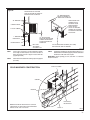
Thru-the-wall Installation
WARNING
STEP 3.
/$<287&XWDQGIUDPHLQDQRSHQLQJLQWKHGHVLUHGZDOODUHD
using the illustration as a guide (See Figure 23).
STEP 4.
Place the cabinet in the framed opening.
NOTE:
Falling Object Hazard
Not following Installation Instructions
for mounting your air conditioner can
result in property damage, injury, or
death.
STEP 1.
$IWHUUHPRYLQJWKHXQLWIURPVKLSSLQJFDUERQVOLGHFKDVVLVRXW
of cabinet (See Figure 16, page 25).
STEP 2.
5HPRYH the shell channel from the top of the cabinet (See
Figure 15, page 24).
Measure and shim void spaces between the side of cabinet and
wood framing before securing to wall.
STEP 5.
3RVLWLRQWKHIURQWHGJHWRH[WHQGLQWRWKHURRPPLQLPXP
at top of cabinet and 1" minimum at bottom (See Figure 24).
STEP 6.
6HFXUHHDFKVLGHRIWKHFDELQHWZLWK1R[KH[KHDG
VFUHZVLWHPSDJHRUQDLOVWKURXJKWKHKROHVLQWKH
sides.
NOTE: $OWHUQDWH IDVWHQHUV ZKLFK PD\ EH XVHG IRU VHFXULQJ WKH XQLW
cabinet to a wall, including masonry walls, are not furnished
(available at local hardware stores).
NOTE: 1RWDSSOLFDEOHWRKHDWSXPSPRGHOVVROGZLWKRXWTXLFNPRXQWLQJ
cabinet.
MOLLY OR TOGGLE BOLT
EXPANSION ANCHOR BOLT
Figure 23
”x8
2
”F
E
M
A
R
INIS
F
DO
E
H
NINGS
E
P
IZ
E
”
0
2
”
0
2
-/”
4
1
-/”
4
1
CONCRETE BLOCK CONSTRUCTION
FRAME CONSTRUCTION
1
9
0
R
F
28
Figure 24
FRONT EDGE OF LOUVERS
MUST ALWAYS BE OUTSIDE OF
EXTERIOR WALL SURFACE.
3/4” MINIMUM FRONT
EDGE OF CABINET TO
INSIDE WALL SURFACE.
3/4” MINIMUM
TRIM AROUND THE
CABINET WITH A
SUITABLE WOOD
MOULDING AND
FINISH TO SUIT.
CAULK ALL AROUND
CABINET ON OUTSIDE
TO INSURE A WEATHER
TIGHT SEAL.
CABINET FRONT
1” THICK LUMBER
1” MINIMUM
1/4” SLOPE DOWN.
POSITION AND SECURE
CABINET DOWNWARD.
SLOPE OUTSIDE FOR
DRAINAGE.
INSIDE WALL
EXTERIOR WALL
MAX. WALL
THICKNESS
ALLOWED 8-1/2”
STEP 7.
STEP 8.
&XWWZRSLHFHVRIVWDQGDUGOXPEHUVXSSOLHGE\LQVWDOOHU
to the length and width required. Place in front and back of
bottom sill channel as shown in Figure 24. Secure with nails
(supplied by installer).
Seal all holes in the cabinet with caulking compound (supplied
by installer).
7/8” SLOTTED HEAD SCREWS (3 EA. SIDE)
NAILS MAY BE USED IF DESIRED.
FRR092
STEP 9.
&RPSOHWHWKHLQVWDOODWLRQE\IROORZLQJ67(36WKURXJKRI
6WDQGDUG:LQGRZ,QVWDOODWLRQ3DJH:LQGRZ6HDO*DVNHW
mentioned in STEP 9 will not be required.
IMPORTANT: %HIRUH RSHUDWLQJ \RXU XQLW UHDG 67(3 RI 6WDQGDUG
Window Instructions.
Figure 25
SOLID MASONRY CONSTRUCTION
CAULK ALL SIDES
CABINET
MORTAR
ELECTRICAL
RECEPTACLE
NOTE: ELECTRICAL RECEPTACLE LOCATION
FROM POINT “X” MUST BE WITHIN A MAXIMUM
RADIUS OF 69” FOR 115V UNITS.
POINT “X”
FRR093
29
Final Inspection & Start-up Checklist
Inspect and ensure that all components and accessories have been
installed properly and that they have not been damaged during the
installation progress.
&KHFNWKHFRQGHQVDWHZDWHUGUDLQVWRHQVXUHWKDWWKH\DUHDGHTXDWH
for the removal of condensate water, and that they meet the approval
of the end user.
Ensure that all installation instructions concerning clearances around
WKHXQLWKDYHEHHQDGKHUHGWR&KHFNWRHQVXUHWKDWWKHXQLWDLU¿OWHU
indoor coil, and outdoor coil are free from any obstructions.
Ensure that the circuit breaker(s) or fuse(s) and supply circuit wire
VL]HKDYHEHHQVL]HGFRUUHFWO\,IWKHXQLWZDVVXSSOLHGZLWKDSRZHU
supply cord, insure that it is stored properly.
Ensure that the entire installation is in compliance with all applicable
QDWLRQDODQGORFDOFRGHVDQGRUGLQDQFHVKDYLQJMXULVGLFWLRQ
Secure components and accessories, such as a decorative front
cover.
Start the unit and check for proper operation of all components in
each mode of operation.
Instruct the owner or operator of the units operation, and the
PDQXIDFWXUHU
V5RXWLQH0DLQWHQDQFH
NOTE: $ORJIRUUHFRUGLQJWKHGDWHVRIPDLQWHQDQFHDQGRUVHUYLFHLV
recommended.
Present the owner or operator of the equipment with the Installation
2SHUDWLRQ0DQXDODOODFFHVVRU\LQVWDOODWLRQLQVWUXFWLRQVDQGWKH
QDPHDGGUHVVDQGWHOHSKRQHQXPEHURIWKH$XWKRUL]HG)ULHGULFK
:DUUDQW\ 6HUYLFH &RPSDQ\ LQ WKH DUHD IRU IXWXUH UHIHUHQFH LI
necessary.
30
This is a warm weather appliance
<RXUDLUFRQGLWLRQHULVGHVLJQHGWRFRROLQZDUPZHDWKHUZKHQWKHRXWVLGH
WHPSHUDWXUHLVDERYH)&DQGEHORZ)&VRLWZRQ
W
cool a room if it is already cool outside.
Condensation is normal
$LUFRQGLWLRQHUVDFWXDOO\SXPSWKHKHDWDQGKXPLGLW\IURP\RXUURRPWRWKH
outside. Humidity becomes water, and your air conditioner will use most
RIWKHZDWHUWRNHHSWKHRXWVLGHFRLOFRRO,IWKHUHLVH[FHVVLYHKXPLGLW\
WKHUHPD\EHH[FHVVZDWHUWKDWZLOOGULSRXWVLGH7KLVLVQRUPDORSHUDWLRQ
Frosting
7KLVXVXDOO\RFFXUVEHFDXVHRILQVXI¿FLHQWDLUÀRZDFURVVWKHFRLOVDGLUW\
¿OWHUFRROGDPSZHDWKHURUDOORIWKHVH6HWWKH6<67(0PRGHWR)$1
21/< and the frost will disappear. Setting the thermostat a little warmer
will probably prevent the frosting from recurring.
Noises
$OO DLU FRQGLWLRQHUV PDNH VRPH QRLVH )ULHGULFK XQLWV DUH GHVLJQHG WR
RSHUDWHDVTXLHWO\DVSRVVLEOH$QDLUFRQGLWLRQHUPRXQWHGLQDZDOOLVTXLHWHU
than one mounted in a window. It is important to ensure that the chassis
seal gasket (Item 14) is properly installed (refer to installation instructions).
Routine Maintenance
Service and Assistance
7RHQVXUHSURSHUXQLWRSHUDWLRQWKHDLU¿OWHUVVKRXOGEHFOHDQHGDWOHDVW
monthly, and more frequently if conditions warrant. The unit must be turned
RIIEHIRUHWKH¿OWHUVDUHFOHDQHG
%HIRUHFDOOLQJIRUVHUYLFHSOHDVHFKHFNWKH³7URXEOHVKRRWLQJ7LSV´VHFWLRQDERYH7KLVPD\KHOS\RXWR¿QGWKHDQVZHUWR\RXUSUREOHPDYRLG
unnecessary service calls, and save you the cost of a service call if the
problem is not due to the product itself.
To Remove, Wash and Replace Filter
/RZHUIURQWSDQHO6HH)LJXUH8VHKDQGOHRQ¿OWHUWRÀH[¿OWHUXSDQG
RXWRIUHWDLQHU5HPRYH¿OWHUIURPXQLW6HH)LJXUH&OHDQ¿OWHUPRQWKO\
RUPRUHIUHTXHQWO\LIQHHGHG5HIHUWRDFFHVVRULHVVHFWLRQIRU¿OWHURSWLRQV
Coils & Chassis
NOTE:
'RQRWXVHDFDXVWLFFRLOFOHDQLQJDJHQWRQFRLOVRUEDVHSDQ
Use a biodegradable cleaning agent and degreaser. The use
of harsh cleaning materials may lead to deterioration of the
DOXPLQXP¿QVRUWKHFRLOHQGSODWHV
The indoor coil and outdoor coils and base pan should be inspected
periodically (annually or semi-annually) and cleaned of all debris (lint, dirt,
OHDYHVSDSHUHWFDVQHFHVVDU\8QGHUH[WUHPHFRQGLWLRQVPRUHIUHTXHQW
FOHDQLQJPD\EHUHTXLUHG&OHDQWKHFRLOVDQGEDVHSDQZLWKDVRIWEUXVK
DQGFRPSUHVVHGDLURUYDFXXP$SUHVVXUHZDVKHUPD\DOVREHXVHG
KRZHYHU\RXPXVWEHFDUHIXOQRWWREHQGWKHDOXPLQXP¿QSDFN8VHD
VZHHSLQJXSDQGGRZQPRWLRQLQWKHGLUHFWLRQRIWKHYHUWLFDODOXPLQXP¿Q
pack when pressure cleaning coils.
NOTE:
,W LV H[WUHPHO\ LPSRUWDQW WR LQVXUH WKDW QRQH RI WKH HOHFWULFDO
DQGRUHOHFWURQLFSDUWVRIWKHXQLWJHWZHW%HVXUHWRFRYHUDOO
electrical components to protect them from water or spray.
Decorative Front
The decorative front and discharge air grille may be cleaned with a mild
VRDSRUGHWHUJHQW'R127XVHVROYHQWVRUK\GURFDUERQEDVHGFOHDQHUV
VXFKDVDFHWRQHQDSKWKDJDVROLQHEHQ]HQHHWFWRFOHDQWKHGHFRUDWLYH
front or air discharge grilles.
<RXFDQ¿QGWKHQDPHRI\RXUORFDO$XWKRUL]HG6HUYLFH3URYLGHUE\YLVLWLQJ
our web site at www.friedrich.com.
If you require further assistance
<RXFDQFDOOWKH&XVWRPHU6XSSRUW&DOO&HQWHUDW1-800-541-6645.
%HIRUHFDOOLQJSOHDVHPDNHVXUHWKDW\RXKDYHWKHFRPSOHWHPRGHODQG
VHULDO QXPEHU DQG GDWH RI SXUFKDVH RI \RXU HTXLSPHQW DYDLODEOH %\
providing us with this information, we will be better able to assist you.
Our specialists are able to assist you with:
6SHFL¿FDWLRQVDQG)HDWXUHVRIRXUHTXLSPHQW
5HIHUUDOVWRGHDOHUVDQGGLVWULEXWRUV
8VHDQG&DUH,QIRUPDWLRQ
5HFRPPHQGHGPDLQWHQDQFHSURFHGXUHV
Installation information.
5HIHUUDOVWR$XWKRUL]HG6HUYLFH3URYLGHUVDQG3DUWVGHSRWV
Available Accessories
Carbon Filter Kits
(DFKNLWFRQWDLQVWKUHH¿OWHUV
KWCFQ&DUERQ¿OWHUNLWIRU4FKDVVLVPRGHOV
Remote Wall Thermostats
Use a damp (not wet) cloth when cleaning the control area to prevent
water from entering the unit, and possibly damaging the electronic control.
RT6±'LJLWDOZDOOWKHUPRVWDWKDUGZLUHGZLWKVLQJOHVWDJHFRRODQGKHDW
with two fan speed selection, battery backup and backlight display
Fan Motor & Compressor
Window Installation Kits
The fan motor & compressor are permanently lubricated, and require no
additional lubrication.
6WDQGDUGLQ.KO0RGHOVZLWKRXW+HDW
Wall Sleeve
Inspect the inside of the wall sleeve and drain system periodically (annually
RUVHPLDQQXDOO\DQGFOHDQDVUHTXLUHG8QGHUH[WUHPHFRQGLWLRQVPRUH
IUHTXHQWFOHDQLQJPD\EHQHFHVVDU\&OHDQERWKRIWKHVHDUHDVZLWKDQ
DQWLEDFWHULDODQGDQWLIXQJDOFOHDQHU5LQVHERWKLWHPVWKRURXJKO\ZLWKZDWHU
DQGHQVXUHWKDWWKHGUDLQRXWOHWVDUHRSHUDWLQJFRUUHFWO\&KHFNWKHVHDODQW
around the sleeve and reseal areas as needed.
KWIKQ
FriedrichLink™ Adapter Accessory:
KWIFI )ULHGULFK/LQN $GDSWHU $FFHVVRU\ IRU ZLUHOHVV FRQWURO DQG
additional programming options
Decorative Color Front Panel Kits:
KWBGEQA40RGHO'HFRUDWLYH)URQW&RYHULQ&ODVVLF%HLJH
KWBLKQA40RGHO'HFRUDWLYH)URQW&RYHULQ%ODFN2Q\[
KWBLUQA40RGHO'HFRUDWLYH)URQW&RYHULQ&REDOW%OXH
KWPNKQA40RGHO'HFRUDWLYH)URQW&RYHULQ3LQN'LDPRQG
KWREDQA 40RGHO'HFRUDWLYH)URQW&RYHULQ'HHS5HG
KWWHTQA 40RGHO'HFRUDWLYH)URQW&RYHULQ'HVLJQHU:KLWH
See www.friedrich.com for additional accessories for your unit.
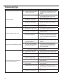
Troubleshooting Tips
&203/$,17
Unit does not operate.
8QLW7ULSV&LUFXLW%UHDNHURU%ORZV)XVHV
&$86(
62/87,21
Ɣ
The unit is turned to the off position,
RUWKHWKHUPRVWDWLVVDWLV¿HG
Ɣ
Turn the unit to the on position and raise or lower
temperature setting (as appropriate) to call for
operation.
Ɣ
7KH/&',SRZHUFRUGLVXQSOXJJHG
Ɣ
Plug into a properly grounded 3 prong receptacle.
6HH³(OHFWULFDO5DWLQJ7DEOHV´RQSJIRUWKH
proper receptacle type for your unit.
Ɣ
7KH/&',SRZHUFRUGKDVWULSSHG
5HVHWEXWWRQKDVSRSSHGRXW
Ɣ
3UHVVDQGUHOHDVH5(6(7OLVWHQIRUFOLFN5HVHW
button latches and remains in) to resume operation.
Ɣ
The circuit breaker has tripped or
the supply circuit fuse has blown.
Ɣ
5HVHWWKHFLUFXLWEUHDNHURUUHSODFHWKHIXVHDV
applicable. If the problem continues, contact a
licensed electrician.
Ɣ
There has been a local power
failure.
Ɣ
The unit will resume normal operation once power
has been restored.
Ɣ
2WKHUDSSOLDQFHVDUHEHLQJXVHGRQ
the same circuit.
Ɣ
The unit requires a dedicated outlet circuit, not
shared with other appliances.
Ɣ
$QH[WHQVLRQFRUGLVEHLQJXVHG
Ɣ
'R127XVHDQH[WHQVLRQFRUGZLWKWKLVRUDQ\
other air conditioner.
Ɣ
The circuit breaker or time-delay
fuse is not of the proper rating.
Ɣ
5HSODFHZLWKDFLUFXLWEUHDNHURUWLPHGHOD\IXVH
RIWKHSURSHUUDWLQJ6HH³(OHFWULFDO5DWLQJ7DEOHV´
RQSJIRUWKHSURSHUFLUFXLWEUHDNHUIXVHUDWLQJ
for your unit. If the problem continues, contact a
licensed electrician.
Ɣ
7KH/&',SRZHUFRUGFDQWULS5HVHW Ɣ
button pops out) due to disturbances
on your power supply line.
Ɣ
Electrical overload, overheating, or
FRUGSLQFKLQJFDQWULS5HVHWEXWWRQ
SRSVRXWWKH/&',SRZHUFRUG
/&',3RZHU&RUG7ULSV5HVHW%XWWRQ3RSV2XW
Ɣ
3UHVVDQGUHOHDVH5(6(7OLVWHQIRUFOLFN5HVHW
button latches and remains in) to resume normal
operation.
2QFHWKHSUREOHPKDVEHHQGHWHUPLQHGDQG
FRUUHFWHGSUHVVDQGUHOHDVH5(6(7OLVWHQIRU
FOLFN5HVHWEXWWRQODWFKHVDQGUHPDLQVLQWR
resume normal operation.
127($GDPDJHGSRZHUVXSSO\FRUGPXVWEHUHSODFHGZLWKDQHZSRZHUVXSSO\FRUGREWDLQHG
from the product manufacturer and must not be repaired.
8QLW'RHV1RW&RRO+HDW5RRP6XI¿FLHQWO\2U
&\FOHV2Q$QG2II7RR)UHTXHQWO\
32
Ɣ
7KHUHWXUQGLVFKDUJHDLUJULOOHLV
blocked.
Ɣ
(QVXUHWKDWWKHUHWXUQDQGRUGLVFKDUJHDLUSDWKV
are not blocked by curtains, blinds, furniture, etc.
Ɣ
Windows or doors to the outside are
open.
Ɣ
Ensure that all windows and doors are closed.
Ɣ
The temperature is not set at a cool
HQRXJKZDUPHQRXJKVHWWLQJ
Ɣ
$GMXVWWKH7HPSHUDWXUHFRQWUROWRDFRROHURU
warmer setting as necessary.
Ɣ
7KH¿OWHULVGLUW\RUREVWUXFWHG
Ɣ
&OHDQWKH¿OWHU6HH5RXWLQH0DLQWHQDQFHRU
remove obstruction.
Ɣ
The indoor coil or outdoor coil is
dirty or obstructed.
Ɣ
&OHDQWKHFRLOV6HH5RXWLQH0DLQWHQDQFHRU
remove obstruction.
Ɣ
7KHUHLVH[FHVVLYHKHDWRUPRLVWXUH
(cooking, showers, etc.) in the room.
Ɣ
%HVXUHWRXVHH[KDXVWYHQWIDQVZKLOHFRRNLQJ
or bathing and, if possible, try not to use heat
producing appliances during the hottest part of the
day.
Ɣ
The temperature of the room you
DUHWU\LQJWRFRROLVH[WUHPHO\KRW
Ɣ
$OORZDGGLWLRQDOWLPHIRUWKHDLUFRQGLWLRQHUWRFRRO
off a very hot room.
&203/$,17
8QLW'RHV1RW&RRO+HDW5RRP6XI¿FLHQWO\2U
&\FOHV2Q$QG2II7RR)UHTXHQWO\FRQWLQXHG
&$86(
62/87,21
Ɣ
The outside temperature is below
)&
Ɣ
'RQRWWU\WRRSHUDWH\RXUDLUFRQGLWLRQHULQWKH
cooling mode when the outside temperature is
EHORZ)&7KHXQLWZLOOQRWFRROSURSHUO\
and the unit may be damaged.
Ɣ
The digital control is set to fan
cycling mode.
Ɣ
Since the fan does not circulate the room air
continuously at this setting, the room air does not
PL[DVZHOODQGKRWRUFROGVSRWVPD\UHVXOW
Using the continuous fan setting is recommended
to obtain optimum comfort levels.
Ɣ
7KHDLUFRQGLWLRQHUKDVLQVXI¿FLHQW
cooling capacity to match the heat
gain of the room.
Ɣ
&KHFNWKHFRROLQJFDSDFLW\RI\RXUXQLWWRHQVXUHLW
LVSURSHUO\VL]HGIRUWKHURRPLQZKLFKLWLVLQVWDOOHG
5RRPDLUFRQGLWLRQHUVDUHQRWGHVLJQHGWRFRRO
multiple rooms.
Ɣ
7KHDLUFRQGLWLRQHUKDVLQVXI¿FLHQW
heating capacity to match the heat
loss of the room.
Ɣ
&KHFNWKHKHDWLQJFDSDFLW\RI\RXUXQLW$LU
FRQGLWLRQHUVDUHVL]HGWRPHHWWKHFRROLQJORDG
DQGKHDWHUVL]HLVWKHQVHOHFWHGWRPHHWWKH
KHDWLQJORDG,QH[WUHPHQRUWKHUQFOLPDWHVURRP
air conditioners may not be able to be used as a
primary source of heat.
Ɣ
7KLVPD\EHGXHWRDQH[FHVVLYH
heat load in the room.
Ɣ
If there are heat producing appliances in use in the
room, or if the room is heavily occupied, the unit will
need to run longer to remove the additional heat.
Ɣ
It may also be due to an improperly
VL]HGXQLW
Ɣ
%HVXUHWRXVHH[KDXVWYHQWIDQVZKLOHFRRNLQJ
or bathing and, if possible, try not to use heat
producing appliances during the hottest part of the
day.
Ɣ
This may be normal for higher
HI¿FLHQF\((5DLUFRQGLWLRQHUV
Ɣ
7KHXVHRIKLJKHUHI¿FLHQF\FRPSRQHQWVLQ\RXU
new air conditioner may result in the unit running
longer than you feel it should. This may be more
DSSDUHQWLILWUHSODFHGDQROGHUOHVVHI¿FLHQW
model. The actual energy usage, however, will be
VLJQL¿FDQWO\OHVVZKHQFRPSDUHGWRROGHUPRGHOV
Ɣ
<RXPD\QRWLFHWKDWWKHGLVFKDUJH
air temperature of your new air
conditioner may not seem as cold
as you may be accustomed to from
older units. This does not, however,
indicate a reduction in the cooling
capacity of the unit.
Ɣ
7KHHQHUJ\HI¿FLHQF\UDWLR((5DQGFRROLQJ
FDSDFLW\UDWLQJ%WXKOLVWHGRQWKHXQLW¶VUDWLQJ
SODWHDUHERWKDJHQF\FHUWL¿HG
8QLW5XQV7RR0XFK
33
Addendum 1
Schedule Table with Energy Saving Values
Residenal Schedule
Period
600
Cool
Auto
Low
78
70
800
Cool
Auto
Low
85
62
Mon
Start Time
System Mode
Fan Mode
Fan Speed
Set Point Cool
Set Point Heat
Start Time
System Mode
Fan Mode
Fan Speed
Set Point Cool
Set Point Heat
3
Start Time
System Mode
Fan Mode
Fan Speed
Set Point Cool
Set Point Heat
1800
Cool
Auto
Low
78
70
4
Start Time
System Mode
Fan Mode
Fan Speed
Set Point Cool
Set Point Heat
1
2
Sun
Start Time
System Mode
Fan Mode
Fan Speed
Set Point Cool
Set Point Heat
Start Time
System Mode
Fan Mode
Fan Speed
Set Point Cool
Set Point Heat
600
Cool
Auto
Low
78
70
800
Cool
Auto
Low
85
62
Tues
Start Time
System Mode
Fan Mode
Fan Speed
Set Point Cool
Set Point Heat
Start Time
System Mode
Fan Mode
Fan Speed
Set Point Cool
Set Point Heat
600
Cool
Auto
Low
78
70
800
Cool
Auto
Low
85
62
Wed
Start Time
System Mode
Fan Mode
Fan Speed
Set Point Cool
Set Point Heat
Start Time
System Mode
Fan Mode
Fan Speed
Set Point Cool
Set Point Heat
600
Cool
Auto
Low
78
70
800
Cool
Auto
Low
85
62
Thur
Start Time
System Mode
Fan Mode
Fan Speed
Set Point Cool
Set Point Heat
Start Time
System Mode
Fan Mode
Fan Speed
Set Point Cool
Set Point Heat
600
Cool
Auto
Low
78
70
800
Cool
Auto
Low
85
62
Fri
Start Time
System Mode
Fan Mode
Fan Speed
Set Point Cool
Set Point Heat
Start Time
System Mode
Fan Mode
Fan Speed
Set Point Cool
Set Point Heat
600
Cool
Auto
Low
78
70
800
Cool
Auto
Low
85
62
Sat
Start Time
System Mode
Fan Mode
Fan Speed
Set Point Cool
Set Point Heat
Start Time
System Mode
Fan Mode
Fan Speed
Set Point Cool
Set Point Heat
600
Cool
Auto
Low
78
70
800
Cool
Auto
Low
85
62
Start Time
System Mode
Fan Mode
Fan Speed
Set Point Cool
Set Point Heat
1800
Cool
Auto
Low
78
70
Start Time
System Mode
Fan Mode
Fan Speed
Set Point Cool
Set Point Heat
1800
Cool
Auto
Low
78
70
Start Time
System Mode
Fan Mode
Fan Speed
Set Point Cool
Set Point Heat
1800
Cool
Auto
Low
78
70
Start Time
System Mode
Fan Mode
Fan Speed
Set Point Cool
Set Point Heat
1800
Cool
Auto
Low
78
70
Start Time
System Mode
Fan Mode
Fan Speed
Set Point Cool
Set Point Heat
1800
Cool
Auto
Low
78
70
Start Time
System Mode
Fan Mode
Fan Speed
Set Point Cool
Set Point Heat
1800
Cool
Auto
Low
78
70
2200
Cool
Auto
Low
82
62
Start Time
System Mode
Fan Mode
Fan Speed
Set Point Cool
Set Point Heat
2200
Cool
Auto
Low
82
62
Start Time
System Mode
Fan Mode
Fan Speed
Set Point Cool
Set Point Heat
2200
Cool
Auto
Low
82
62
Start Time
System Mode
Fan Mode
Fan Speed
Set Point Cool
Set Point Heat
2200
Cool
Auto
Low
82
62
Start Time
System Mode
Fan Mode
Fan Speed
Set Point Cool
Set Point Heat
2200
Cool
Auto
Low
82
62
Start Time
System Mode
Fan Mode
Fan Speed
Set Point Cool
Set Point Heat
2200
Cool
Auto
Low
82
62
Start Time
System Mode
Fan Mode
Fan Speed
Set Point Cool
Set Point Heat
2200
Cool
Auto
Low
82
62
700
Cool
Auto
Med
84
62
1800
Cool
Auto
Med
84
62
Mon
Start Time
System Mode
Fan Mode
Fan Speed
Set Point Cool
Set Point Heat
Start Time
System Mode
Fan Mode
Fan Speed
Set Point Cool
Set Point Heat
700
Cool
Auto
Med
75
70
1800
Cool
Auto
Med
84
62
Tues
Start Time
System Mode
Fan Mode
Fan Speed
Set Point Cool
Set Point Heat
Start Time
System Mode
Fan Mode
Fan Speed
Set Point Cool
Set Point Heat
Thur
Start Time
System Mode
Fan Mode
Fan Speed
Set Point Cool
Set Point Heat
Start Time
System Mode
Fan Mode
Fan Speed
Set Point Cool
Set Point Heat
700
Cool
Auto
Med
75
70
1800
Cool
Auto
Med
84
62
Fri
Start Time
System Mode
Fan Mode
Fan Speed
Set Point Cool
Set Point Heat
Start Time
System Mode
Fan Mode
Fan Speed
Set Point Cool
Set Point Heat
700
Cool
Auto
Med
75
70
1800
Cool
Auto
Med
84
62
Sat
Start Time
System Mode
Fan Mode
Fan Speed
Set Point Cool
Set Point Heat
Start Time
System Mode
Fan Mode
Fan Speed
Set Point Cool
Set Point Heat
700
Cool
Auto
Med
84
62
1800
Cool
Auto
Med
84
62
Commercial Schedule
Period
1
2
34
Sun
Start Time
System Mode
Fan Mode
Fan Speed
Set Point Cool
Set Point Heat
Start Time
System Mode
Fan Mode
Fan Speed
Set Point Cool
Set Point Heat
700
Cool
Auto
Med
75
70
1800
Cool
Auto
Med
84
62
Wed
Start Time
System Mode
Fan Mode
Fan Speed
Set Point Cool
Set Point Heat
Start Time
System Mode
Fan Mode
Fan Speed
Set Point Cool
Set Point Heat
700
Cool
Auto
Med
75
70
1800
Cool
Auto
Med
84
62
Friedrich Air Conditioning Company
10001 Reunion Place, Suite 500
San Antonio, TX 78216
800.541.6645
www.friedrich.com
ROOM AIR CONDITIONERS
LIMITED WARRANTY
FIRST YEAR
ANY PART: If any part supplied by FRIEDRICH fails because of a defect in workmanship or material within twelve months from
date of original purchase, FRIEDRICH will repair the product at no charge, provided room air conditioner is reasonably accessible
for service. Any additional labor cost for removing inaccessible units and/or charges for mileage related to travel by a Service
Agency that exceeds 25 miles one way will be the responsibility of the owner. This remedy is expressly agreed to be the exclusive
remedy within twelve months from the date of the original purchase.
SECOND THROUGH FIFTH YEAR
SEALED REFRIGERANT SYSTEM: If the Sealed Refrigeration System (defined for this purpose as the compressor, condenser
coil, evaporator coil, reversing valve, check valve, capillary, filter drier, and all interconnecting tubing) supplied by FRIEDRICH in
your Room Air Conditioner fails because of a defect in workmanship or material within sixty months from date of purchase,
FRIEDRICH will pay a labor allowance and parts necessary to repair the Sealed Refrigeration System; PROVIDED FRIEDRICH will
not pay the cost of diagnosis of the problem, removal, freight charges, and transportation of the air conditioner to and from the
Service Agency, and the reinstallation charges associated with repair of the Sealed Refrigeration System. All such cost will be the
sole responsibility of the owner. This remedy is expressly agreed to be the exclusive remedy within sixty months from the date of the
original purchase.
APPLICABILITY AND LIMITATIONS: This warranty is applicable only to units retained within the Fifty States of the U.S.A., District
of Columbia, and Canada. This warranty is not applicable to:
1.
2.
3.
Air filters, fuses, batteries and the front grille removal tool.
Products on which the model and serial numbers have been removed.
Products which have defects or damage which results from improper installation, wiring, electrical current
characteristics, or maintenance; or caused by accident, misuse or abuse, fire, flood, alterations and/or misapplication
of the product and/or units installed in a corrosive atmosphere, default or delay in performance caused by war,
government restrictions or restraints, strikes, material shortages beyond the control of FRIEDRICH, or acts of God.
OBTAINING WARRANTY PERFORMANCE: Service will be provided by the FRIEDRICH Authorized Dealer or Service
Organization in your area. They are listed in the Yellow Pages. If assistance is required in obtaining warranty performance, write
to: Room Air Conditioner Service Manager, Friedrich Air Conditioning Co., 10001 Reunion Place, Ste.500, San Antonio, TX., 78216.
LIMITATIONS:
THIS WARRANTY IS GIVEN IN LIEU OF ALL OTHER WARRANTIES. Anything in the warranty
notwithstanding, ANY IMPLIED WARRANTIES OF FITNESS FOR PARTICULAR PURPOSE AND/OR MERCHANTABILITY
SHALL BE LIMITED TO THE DURATION OF THIS EXPRESS WARRANTY. MANUFACTURER EXPRESSLY DISCLAIMS AND
EXCLUDES ANY LIABILITY FOR CONSEQUENTIAL OR INCIDENTAL DAMAGE FOR BREACH OF ANY EXPRESSED OR
IMPLIED WARRANTY.
Performance of Friedrich’s Warranty obligation is limited to one of the following methods:
1. Repair of the unit
2. A refund to the customer for the prorated value of the unit based upon the remaining warranty period of the unit.
3. Providing a replacement unit of equal value
The method of fulfillment of the warranty obligation is at the sole discretion of Friedrich Air Conditioning.
NOTE: Some states do not allow limitations on how long an implied warranty lasts, or do not allow the limitation or exclusion of
consequential or incidental damages, so the foregoing exclusions and limitations may not apply to you.
OTHER: This warranty gives you specific legal rights, and you may also have other rights which vary from state to state.
PROOF OF PURCHASE: Owner must provide proof of purchase in order to receive any warranty related services.
All service calls for explaining the operation of this product will be the sole responsibility of the consumer.
All warranty service must be provided by an Authorized FRIEDRICH Service Agency, unless authorized by FRIEDRICH prior to
repairs being made.
35
Friedrich Air Conditioning Co.
5HXQLRQ3ODFH6XLWH6DQ$QWRQLR7H[DV
1-800-541-66450
www.friedrich.com
Printed in the U.S.A.
93001001_00