1
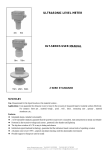
INSTALLATION, OPERATION AND MAINTENANCE MANUAL
DUAL MOTOR PACKAGED TERMINAL
AIR CONDITIONERS
RC 11, 12 & 21
RC/RH 10, 20, 35, 45, 80, 90
RC11
RC/RH10
RC12
RC/RH20
RC21
RC/RH35
RC/RH80
Enviromaster International LLC
5780 Success Dr.
Rome, NY 13440
www.retroaire.com
An ISO 9001-2000 Certified Company
P/N# 240004146, Rev. 1.7 [02/07]
DUAL MOTOR PACKAGED TERMINAL AIR CONDITIONERS
INSTALLATION, OPERATION, AND MAINTENANCE MANUAL
P/N# 240004146, Rev. 1.7 [02/07]
Shipping Damage MUST be Reported to the Carrier IMMEDIATELY!!!
Examine the exterior. Remove cover and examine compressor and piping for signs of damage.
SAFETY INSTRUCTIONS
This manual is intended as an aid to qualified service
personnel for proper installation, operation, and maintenance of the RetroAire Dual Motor Packaged Terminal Air
Conditioner (PTAC). Read these instructions thoroughly
and carefully before attempting installation or operation.
Failure to follow these instructions may result in improper
installation, operation, service or maintenance, possibly
resulting in fire, electrical shock, property damage, personal
injury, or death.
Read all instructions before using the RetroAire
PTAC. Install or locate this unit only in accordance
with these instructions. Use this unit only for its
intended use as described in this manual.
Check the rating plate on the RetroAire PTAC before
installation to make certain the voltage shown is the
same as the electric supply to the unit.
The RetroAire PTAC must be connected only to a
properly grounded electrical supply. Do not fail to
properly ground this unit.
TO THE INSTALLER
(1) Retain this manual and warranty for future reference.
Turn off the electrical supply before servicing the
RetroAire PTAC.
(2) Before leaving the premises, review this manual to be
sure the unit has been installed correctly and run the
unit for one complete cycle to make sure it functions
properly.
Do not use the RetroAire PTAC if it has damaged
wiring, is not working properly, or has been damaged or dropped.
[Save These Instructions]
To obtain technical service or warranty assistance during or after the installation of this unit, contact your local
representative. Visit our website www.retroaire.com
for a local representative listing. For further assistance
call 1-800-228-9364.
!
When calling for assistance, please have the following
information ready:
Recognize this symbol as an indication
of important safety information
!
• Model Number___________________________
• Serial Number____________________________
• Date of Installation________________________
The Right Fit For Comfort
2
www.retroaire.com
TABLE OF CONTENTS
MODIFICATION AND TAMPERING
Warnings and Precautions ..................................... 2-3
The Dual Motor PTAC Family ................................... 4
Controls and Components ........................................ 4
Preparation for Installation ....................................... 5
Electrical Wiring ....................................................... 5
Installation Instruction for:
RC/RH10 Replacement PTAC ............................. 6
RC11 Replacement PTAC .................................... 7
RC12 Replacement PTAC ................................... 8
RC/RH20 Replacement PTAC ........................ 9-10
RC21 Replacement PTAC .............................11-12
RC/RH35 Replacement PTAC ............................13
RC/RH45 Replacement PTAC .......................14-15
RC/RH80 Replacement PTAC .......................16-17
RC/RH90 Replacement PTAC .......................18-19
Final Inspection and Start-Up..............................20
Sequence of Operation .......................................20-23
Cleaning and Maintenance .....................................24
Troubleshooting .......................................................24
Specifications ...........................................................25
Warranty ..................................................................26
! DANGER !
Tampering with the RetroAire Dual Motor PTAC is
dangerous and may result in serious injury or death.
Tampering voids all warranties. Do not attempt to
modify or change this unit in any way.
IMPORTANT SAFETY FEATURE
Power Cord With Integral Safety Protection
All PTACs rated 250V or less that are cord connected
to the power supply are equipped with a power cord
with integral safety protection as standard. Providing
personal shock protection as well as arcing and
fire prevention, the device is designed to sense
any damage in the line cord and disconnect power
before a fire can occur. Tested in accordance with
Underwriters Laboratories, the cord set also offers a
unique “passive” operation, meaning the unit does not
require resetting if main power is interrupted.
INSTALLER RESPONSIBILITIES
WARNING - A DAMAGED POWER SUPPLY CORD
MUST BE REPLACED WITH A NEW CORD FROM
THE MANUFACTURER, AND NOT REPAIRED.
This manual has been prepared to acquaint you with the
installation, operation and maintenance of RetroAire Dual
Motor PTACs and to provide important safety information
in these areas.
Each power cord should be checked before every
use. Follow the instructions in the order listed on the
device.
We urge you to read all of these instructions thoroughly
before attempting the installation or operation of your unit.
This manual should be kept for future reference.
WARNING - DO NOT USE THE PRODUCT IF THE
UNIT FAILS THE TEST.
The manufacturer of this unit will not be liable for any
damages caused by failure to comply with the installation
and operating instructions outlined in this manual.
!
Do not use the RetroAire Dual Motor PTAC with
any electrical supply voltage other than the one
listed on the rating plate.
A rating plate identifying your RetroAire Dual Motor
PTAC can be found on the unit. When referring to your
unit, always have the information listed on the rating plate
readily available.
!
WARNING
!
DANGER
! CAUTION
!
!
PTAC Chasses are heavy. To avoid injury, use
assistance when lifting.
Completely read all instructions prior to assembling,
installing, operating, or repairing this product. Inspect
all parts for damage prior to installation and start-up.
Note: Unit uses R22 refrigerant.
The Right Fit For Comfort
3
www.retroaire.com
The RetroAire Dual Motor PTAC is available in nominal
sizes of 9,000 Btuh, 12,000 Btuh, 15,000 Btuh, and 18,000
Btuh.* With energy efficiency ratings as high as 10, the
replacement of worn out and inefficient units is a very attractive option.
THE DUAL MOTOR PTAC FAMILY
The RetroAire Dual Motor PTAC is available as a coolingonly model or, for those who wish to up-grade to a heat
pump, the RH10, 20, 35, 45, 80, and 90 heat pump chassis
will fit the existing wall sleeve. The heat pump version will
reduce energy costs during periods of outdoor temperature
ranging down to as low as 40° F.
* The RC12 PTAC, however, is only available in nominal
sizes of 12,000 Btuh and 15,000 Btuh.
All Retroaire products are backed by Enviromaster
International LLC and are rated in accordance with ARI
Standards 310 and 380 and UL Standard 484.
The Dual Motor PTAC uses a high-efficiency rotary compressor protected under a 5-year warranty and an enhanced
high-efficiency heat exchanger to make the replacement of
worn out and inefficient units a very attractive option.
PRE-INSTALLATION
The RetroAire Dual Motor PTAC offers two fan speeds
– three in the RC12 – and has an optional motorized fresh
air feature with a positive pressure seal, override switch, and
positive condensate re-evaporation to improve efficiency.
Test run the Dual Motor PTAC prior to installation. Connect
the line cord to a proper power supply (such as the one the
old unit is plugged into) and check all controls for proper
operation. Disconnect the chassis before installing.
Whisper quiet operation improves the room ambience and
the 20 gauge galvanized steel construction of the chassis
ensures long service life.
Review baffle and foam tape installation to ensure proper
air seal and unit operation.
The RetroAire Dual Motor Packaged Terminal Air Conditioner family consists of:
CONTROLS AND COMPONENTS
Standard Unit Features
RC/RH10: A straight cool/heat pump replacement for
the American Air Filter 16 Series, American Standard
45, Carteret 45, Remington Type 45, McQuay 45,
Singer 45, and Nelson Aire 16.
1. Unit mounted operating controls
• Thermostat
• Fan speed control
• Heat/cool switch
• Fan cycle switch
RC11: A straight cool only replacement for the
Westinghouse RB Series.
2. Low ambient protection
RC12: A straight cool only replacement for the Lennox PTEIA Series.
3. Foam strip seal for supply air duct
4. Weather strip insulation
RC/RH20: A straight cool/heat pump replacement
for the Climate Master (Friedrich) 702 & 703, Cool
Heat RM Series, TPI Ra-Matic, Weather Twin, and
ZoneAire S, SC & RM.
5. Baffle kit bag
RC21: A straight cool only replacement for the Climate Master 701.
7. Sea coast coated drainpan
6. Condenser baffles to accommodate extended wall
sleeve applications (consult factory)
8. Normally/open normally/closed motor valve-switch,
(hydronic heat only)
RC/RH35: A straight cool/heat pump replacement for
the Singer/Remington/McQuay EA, ES & RS.
Optional Controls and Accessories
RC/RH45: A straight cool/heat pump replacement
for the American Standard Type 40.
1. Remote thermostat
2. Motorized fresh air damper
RC/RH80: A straight cool/heat pump replacement for
Fedders CMEO “Unizone,” and Mueller/Worthington
“Climatrol.”
3. Electric/hydronic heat
4. Disconnect switch
RC/RH90: A straight cool/heat pump replacement for
Cool Heat AD & 700 and Friedrich Climate Master
AD & 700.
The Right Fit For Comfort
5. Sea coast coated coils
6. Wall sleeves, louvers, and cabinets (consult factory)
4
www.retroaire.com
! WARNING
!
! WARNING !
Moving parts can cause personal injury. Exercise
all due caution when test running the chassis.
The correct condenser air baffles must be properly
installed or performance will be impaired and/or the
warranty will be voided!!
PREPARATION FOR INSTALLATION
See individual unit installation instructions for more
information.
IMPORTANT: RetroAire Dual Motor PTACs are to be used
with metal wallsleeves. The sleeves must employ front
panels secured by screws that prevent contact with all parts
with minor dimensions of openings not exceeding 1/2”. The
final assembly must employ an indoor air discharge grill
having dimensions not less than 26” x 4”, separating the top
surface of the chassis from the top surface of the discharge
grill by a minimum of 1”. For all models, the outdoor
openings must prevent contact of all moving parts by means
of louvers or grills with minor dimension not exceeding 1”.
All cord connected 265 Volt units must be plugged into
receptacles within the unit subbase or chassis.
ELECTRICAL WIRING
All wiring should be in accordance with the National Electric
Code (NEC) and the local building codes.
! WARNING !
To avoid possible injury or death due to electrical
shock, open the power supply disconnect switch
and secure it in an open position during installation.
On a plug and receptacle connection, keep the unit
unplugged until installation is complete.
1. Remove the front of the existing room enclosure. This
will expose the old chassis.
2. Disconnect the power supply. If a line cord and plug
were used, remove it from the receptacle. If the chassis
is hard wired, locate the circuit breaker, place it in the
“OFF” position, and tag it, announcing work is being
done. DO NOT TURN ON.
1. Inspect the existing wiring for any deficiencies such as
cut or frayed wires. Replace such wiring if found.
2. Check the unit rating plate for circuit ampacity and
breaker or fuse size. Use only HACR type breakers.
Select the proper wire for the ampacity rating.
3. Loosen any tie down bolts or screws and remove the
old chassis.
3. If plug and receptacle are used, check the compatibility.
The chassis can be hard wired or direct connected as
well.
IMPORTANT: Dispose of old chassis per present state
and federal regulations.
4. Each unit must have a separate branch ciruit protected
by a fuse or breaker. Refer to the unit rating plate for the
proper wire and breaker or fuse size. Use of extension
cords is prohibited.
4. Inspect the wall sleeve/cabinet for rust, holes, and damage. Clean the wall sleeve of any dirt, repair any damage,
and ensure proper drainage of condensate or rainwater
to exterior of building.
5. Remove or repair old weather seals and note location
for installation of any new seals.
!
!
The RetroAire Dual Motor PTAC must:
6. Check the wall sleeve/cabinet to assure all drain holes
are open and that (A) the unit is level left to right and (B)
the back is pitched to the outside by 1/2” maximum.
Be connected to a properly grounded electrical
supply with the proper voltage as stated on the
rating plate.
7. Check the present voltage to verify the new chassis is a
matching voltage and that the line cord and receptacle
match.
Use the proper maximum over current protection
device stated on the rating plate.
The use of extension cords is prohibited.
8. Before installing the new chassis, inspect the outdoor
louver for a minimum free area of 70% and remove
any obstructions. Any variation will restrict air flow over
the condenser coil and cause serious damage to the
chassis. It will also void the warranty.
The Right Fit For Comfort
DANGER
Failure to follow these instructions can result in a fire,
explosion or electrical shock causing property damage,
personal injury or death.
5
www.retroaire.com
INSTALLATION INSTRUCTIONS
RC/RH10 REPLACEMENT PTAC
5. Apply one piece of 1/2” x 1/2” open cell polyfoam to top flange
of evaporator block off (See illustration at left).
Install
1/2” x 1/2”
Foam Tape
CK
LO
PB
EVA
6. Apply 2” x 1 1/2” open cell foam strips around supply air
duct to ensure that all the conditioned air is delivered into
the room. Failure to do so results in recirculation of the
conditioned air around the wall sleeve and through the unit
causing the unit to short cycle and coils to freez, thus raising operating costs through improper heating and cooling
(Figure C1).
F
OF
7. 1” x 1” Open cell foam strips are provided to prevent outside air
from entering around the chassis to the room from the sides
and top of the cabinet. Install between wall sleeve and cooling
chassis. It is imperative to have a solid air seal between wall
sleeve and chassis. Failure to do so will result in air leakage
from outdoor to
Figure D1
indoor causing
system problems
Wall Sleeve
i.e. coils freezing,
short cycling, and
constant running
of unit. If installFront View
er is in need of
more foam than
Cooling Chassis
supplied in kit,
1�x1� Foam Tape
consult factory
(Figure D1).
RC/RH10 BAFFLE INSTALLATION KIT
• 1 Installation Manual
• 1 Top Baffle
• 2 Sets of Lt.&Rt. Baffles
• Screws
HYDRONIC
ONLY
• 1/2” x 1/2” Open Cell Foam Tape
• 1” x 1” Open Cell Foam Tape
• 2” x 1 1/2” Open Cell Foam Tape
• 1ea. 2-Position Connector & Pin Mate
• 14AWG Yellow Wire
1. Take unit out of packaging.
2. Slide unit into wall sleeve. If supply duct on cooling chassis does
not line up with supply vent on room cabinet it is possible that
factory installed angle brackets on the top and sides will have
to be reversed. This will allow approximately 1” in or out of the
wall sleeve (see figures A & B) below.
Figure A1
Figure B1
8. Once confident that all seals are the correct size and in the
proper location, and the correct baffles are attached to the condenser coil in the proper orientation, slide unit into final position
and tighten any tie down bolts or screws as necessary.
Hydronic Only: Remove the 2-position connector assembly
from kit bag supplied with unit (this will have 2 yellow wires
attached). Connect this 2-position connector to the 2-position
connection located on the bottom of the control box panel.
Two sets of baffles are provided in your kit to accommodate
mounting brackets in either position A or B.
To Connect Aquastat:
A. Remove the black jumper wire located on the bottom
panel of the control box (this is also terminated with a
2-position connector).
B. Cut the jumper wire in the middle and splice the aquastat
to the jumper.
C. Place the connecter back into original location. Refer
to wire diagram on the unit for details.
3. Slide unit out of wallsleeve.
4. Baffle Installation - Remove baffles from kit bag supplied
with unit. Install left and right side baffles on the condenser
coil in existing holes:
• Choose the proper fitting baffles for your application.
• Baffles must come in contact with the outdoor louver.
• Make sure baffles are
Figure C1
directed inward toward
Baffles Directed Inward
the center of coil.
Toward Coil
• Secure baffles tightly to
the condenser coil using
��������������
CONDENSER
SIDE
the screws provided.
��������
(Figures A1,B1 & C1).
IMPORTANT: The correct
condenser air baffles must
be installed or performances
may be impaired and/or the
warranty will be voided.
The Right Fit For Comfort
���������������
9. Connect line cord.
10. See Final Inspection and Startup on page 20.
RC/RH 10 PERFORMANCE DATA*
Unit Size Cooling Btuh EERs Heat Pump Btuh COP Fresh Air CFM
�������
���
2” X 1 1/2” Supply Air
Duct Foam Tape
9
9,500
10.0
8,500
2.8
40/35
12
11,900
10.0
11,400
2.9
40/35
15
14,700
9.2
13,800
2.8
40/35
18
16,900
9.1
N/A
N/A
40/35
*Refer to the charts on page 23 for electrical and
optional electric heat specifications.
6
www.retroaire.com
INSTALLATION INSTRUCTIONS
RC11 REPLACEMENT PTAC
6. Apply 2” x 1 1/2” open cell foam strips around supply air
duct to ensure that all the conditioned air is delivered
into the room. Failure to do so results in recirculation of
the conditioned air around the wall sleeve and through
the unit causing the unit to short cycle, thus raising
operating costs through improper heating and cooling
(Figure A2).
Removable
Weather Seals
341/2”
393/4”
141/8”
Figure B2
Air Filter
1. Take unit out of packaging.
7. 1” x 1” Open
Wall Sleeve
cell foam strips
are provided to
prevent outside
air from enterFront View
ing around the
chassis to the
Cooling Chassis
room from the
1�x1� Foam Tape
sides and top
of the cabinet. Install between wall sleeve and cooling
chassis. It is imperative to have a solid air seal between
wall sleeve and chassis. Failure to do so will result in
air leakage from outdoor to indoor causing system
problems i.e. Coils freezing, short cycling, and constant
running of unit. If installer is in need of more foam than
supplied in kit, consult factory (Figure B2).
2. Slide unit into wall sleeve. The supply duct on the cooling chassis should line up with the supply vent on the
room cabinet. The weather angles should require no
adjustment.
8. Once confident that all seals are the correct size and in
the proper location, and the correct baffles are attached
to the condenser coil in the proper orientation, slide
unit into final position and tighten any tie down bolts or
screws as necessary.
301/4”
Install
1/2” x 1/2”
Foam Tape
111/4”
187/8”
RC11 BAFFLE INSTALLATION KIT
• 1 Installation Manual
• 1 Top Baffle
• 2 Sets of Lt.&Rt. Baffles
• Screws
HYDRONIC
ONLY
• 1/2” x 1/2” Open Cell Foam Tape
• 1” x 1” Open Cell Foam Tape
• 2” x 1 1/2” Open Cell Foam Tape
• 1 ea. 2-Position Connector & Pin Mate
• 14AWG Yellow Wire
Two sets of baffles are provided in your kit to accommodate
varying wall sleeve depth.
3. Slide unit out of wallsleeve.
Hydronic Only: Remove the 2-position connector assembly from kit bag supplied with unit (this will have 2
yellow wires attached). Connect this 2-position connector
to the 2-position connection located on the bottom of the
control box panel.
IMPORTANT: The correct condenser air baffles must be
installed or performances may be impaired and/or the
warranty will be voided.
4. Baffle Installation - Remove baffles from kit bag supplied with unit. Install left and right side baffles on the
condenser coil in existing holes:
• Choose the proper fitting baffles for your application.
Figure A2
• Baffles must come
Baffles-Directed Inward
in contact with the
Toward Coil
outdoor louver.
• Make sure baffles
��������������
are directed inward
toward the center of
��������
coil.
• Secure baffles tightly
�������
���������������
���
to the condenser coil
using the screws pro2” X 1 1/2” Supply Air
Duct Foam Tape
vided.
To Connect Aquastat:
A. Remove the black jumper wire located on the bottom panel of the control box (this is also terminated
with a 2-position connector).
B. Cut the jumper wire in the middle and splice the
aquastat to the jumper.
C. Place the connecter back into original location.
Refer to wire diagram on the unit for details.
9. Connect line cord.
10. See Final Inspection and Startup on page 20.
RC11 PERFORMANCE DATA*
5. Apply one piece of 1/2” x 1/2” open cell polyfoam to top
flange of evaporator block off (See illustration: top of
this page).
The Right Fit For Comfort
UNIT SIZE
COOLING BTUH
EER
FRESH AIR CFM
9
9500
10
40/35
12
11,900
10
40/35
15
14,700
9.2
40/35
18
16,900
9.1
40/35
*Refer to the charts on page 23 for electrical and
optional electric heat specifications.
7
www.retroaire.com
INSTALLATION INSTRUCTIONS
RC12 REPLACEMENT PTAC
IMPORTANT: If adjoining room conditioning is required, the
RC12 is able to discharge to the right and left by utilizing
the four-inch knockouts (Figure B3) on either side of the
evaporator compartment using 4” flex duct.
3. Once confident that all seals are the correct size and in
the proper location and the correct baffles are attached
to the condenser coil and in the proper orientation, slide
unit into final position and tighten any tie down bolts or
screws as necessary.
Figure B3
Left and Right
Condenser Baffles
1” x 1” Open Cell
Foam Tape
1” X 1/2”
Open Cell
Foam Tape
RC12 INSTALLATION KIT
5/8” Ref.
• 1 Installation Manual
HYDRONIC
ONLY
• 1ea. 2-Position Connector & Pin Mate
• 14AWG Black Wire
Air Intake
1. Take unit out of packaging.
Removeable Filter
2. Slide unit into wall sleeve. The supply duct on the cooling chassis should line up with the supply vent on the
room cabinet. The weather angles should require no
adjustment.
Hydronic Only: Remove the 2-position connector assembly from kit bag supplied with unit (this will have 2
yellow wires attached). Connect this 2-position connector to the 2-position connection located on the bottom
of the control box panel.
3. Make sure baffles come in contact with the outdoor
louver.
IMPORTANT: Baffles and open cellfoam tape seals
are factory installed on the RC12 . Baffles fill the gap
between the rear of the chassis and the outdoor louver
and prevent the air from recirculating. Consult the factory
if baffles supplied are not deep enough to accommodate
wall sleeve application as system efficiency and reliability
are dependent on proper air flow. (Figure A3)
To Connect Aquastat:
A. Remove the black jumper wire located on the
bottom panel of the control box (this is also terminated with a 2-position connector).
B. Cut the jumper wire in the middle and splice the
aquastat to the jumper.
C. Place the connecter back into original location.
Refer to wire diagram on the unit for details.
Figure A3
4. Connect line cord.
Baffles-Directed Inward
Toward Coil
��������������
���������������
5. See Final Inspection and Startup on page 20.
1” X 1 ”
Open Cell
Foam Tape
��������
RC12 PERFORMANCE DATA*
�������
���
1” X 1/2” Supply Air
Duct Foam Tape
The Right Fit For Comfort
4” Knockout
UNIT
SIZE
COOLING
BTUH
EER
EVAP CFM
HIGH/LOW
FRESH
AIR CFM
12
12,200
10
390/340
40/35
15
15,500
9
440/390
40/35
*Refer to the charts on page 23 for electrical and
optional electric heat specifications.
8
www.retroaire.com
INSTALLATION INSTRUCTIONS
RC/RH20 REPLACEMENT PTAC
ADJUSTABLE WEATHER SEAL ANGLE POSITIONS
Two sets of baffles are provided in your kit to accommodate
mounting brackets in either position A or B.
A
8 5/8”
7 7/8”
9 11/16” (1)
8” (2)
B
9 1/2”
10 1/4”
8 7/16”(1)
10 1/8” (2)
NOTE: Dimensions calculated without foam gaskets
(1) Standard position-Factory installed
(2) Position for Climate Master 702 and 703.
Figure A4
Figure B4
REMOVEABLE
WEATHER SEAL
ANGLES
5 1/2”
4”
35 15/16”
3”
22” CONDENSER COIL
2”
8 1/2”
8 1/4”
4. Baffle Installation - Remove baffles from kit bag supplied with unit. Install left and right side baffles on the
condenser coil in existing holes:
• Choose the proper fitting baffles for your application.
• Baffles must come in contact with the outdoor
louver.
• Make sure baffles are directed inward toward the
center of coil.
• Secure baffles tightly to the condenser coil using the
screws provided. (Figures A4,B4 & C4 )
26” AIR OUTLETS
14 13/16”
A
18 1/8”
AIR INTAKE FILTER
B
Figure C4
RC/RH20 BAFFLE INSTALLATION KIT
• 1 Installation Manual
• 1 Lt. & Rt. Baffles (size 1)
• 1 Lt. & Rt. Baffles (size 2)
HYDRONIC
ONLY
Baffles-Directed Inward
Toward Coil
• Screws
• 1” x 1” Open Cell Foam Tape
• 1/2” x 1/2” Open Cell Foam Tape
• 1ea. 2-Position Connector & Pin Mate
• 14AWG Black Wire
��������������
��������
1. Take unit out of packaging.
���������������
2. Slide unit into wall sleeve. If supply duct on cooling
chassis does not line up with supply vent on room
cabinet it is possible that factory instlled angle brackets
on the top and sides will have to be reversed. This will
allow approximately 1” in or out of the wall sleeve (See
figures A4 & B4).
1/2” X 1/2” Supply Air
Duct Foam Tape
5. Apply 1/2” x 1/2” open cell foam strips around supply
air duct to ensure that all the conditioned air is delivered
into the room. Failure to do so results in recirculation of
the conditioned air around the wall sleeve and through
the unit causing the unit to short cycle, thus raising
operating costs through improper heating and cooling
(Figure C4).
3. Slide unit out of wallsleeve.
IMPORTANT: The correct condenser air baffles must be
installed or performances may be impaired and/or the
warranty will be voided.
The Right Fit For Comfort
�������
���
9
www.retroaire.com
RC/RH20 INSTALLATION INSTRUCTIONS (Continued)
6. 1” x 1” Open cell foam strips are provided to prevent
outside air from entering around the chassis to the room
from the sides and top of the cabinet. Install between
wall sleeve and cooling chassis. It is imperative to have
a solid air seal between wall sleeve and chassis. Failure
to do so will result in air leakage from outdoor to indoor
causing system problems i.e. coils freezing, short cycling, and constant running of unit. If installer is in need
of more foam than supplied in kit, consult factory.
Hydronic Only: Remove the 2-position connector assembly from kit bag supplied with unit (this will have 2
yellow wires attached). Connect this 2-position connector to the 2-position connection located on the bottom
of the control box panel.
To Connect Aquastat:
A. Remove the black jumper wire located on the
bottom panel of the control box (this is also terminated with a 2-position connector).
B. Cut the jumper wire in the middle and splice the
aquastat to the jumper.
C. Place the connecter back into original location.
Refer to wire diagram on the unit for details.
Figure D4
Wall Sleeve
8. Connect line cord.
Front View
9. See Final Inspection and Startup on page 20.
Cooling Chassis
1�x1� Foam Tape
7. Once confident that all seals are the correct size and in
the proper location and the correct baffles are attached
to the condenser coil in the proper orientation, slide
unit into final position and tighten any tie down bolts or
screws as necessary.
RC/RH 20 PERFORMANCE DATA*
Unit
Size
Cooling
Btuh
EERs
RC/RH20 Hydronic Heat *
Heat Pump
Btuh
COP
Fresh Air
CFM
Performance 104-101 (Single Row Coil)
GPM
EWT (°F)
Capacities Btuh
P.D.
9
9,500
10
8500
2.8
40/35
180°F Hi
16,400
4.4
12
11,900
10
11400
2.9
40/35
180°F Lo
15,400
4.4
15
14,700
9.2
13800
2.8
40/35
140°F Hi
10,300
4.6
18
16,900
9.1
N/A
N/A
40/35
140°F Lo
9,700
4.6
3.0
*Refer to the charts on page 23 for electrical and optional electric heat specifications.
The Right Fit For Comfort
10
www.retroaire.com
INSTALLATION INSTRUCTIONS
RC21 REPLACEMENT PTAC
DIMENSIONS
MODEL
A
B
C
9-12
20 14”
9 7/8”
10 3/8”
15-18
25 1/4”
10 1/8”
15 3/8”
2. Slide unit out of wallsleeve.
3. Remove baffles from kit bag supplied with unit.
IMPORTANT: The correct condenser air baffles must be
installed or performances may be impaired and/or the
warranty will be voided.
A - OVERALL CHASSIS DEPTH
B - CONDENSER SECTION DEPTH
C - EVAPORATOR SECTION DEPTH
NOTE: Dimensions “A” and “B” are with condenser
recirculation baffles and without weather seal
gasket.
4. Baffle Installation - Install left and right side baffles on
the condenser coil in existing holes:
• Choose the proper fitting baffles for your application.
• Baffles must come in contact with the outdoor louver.
• Make sure baffles are directed inward toward the
center of coil.
• Secure baffles tightly to the condenser coil using the
screws provided. (Figures A5, B5 & C5 )
Condenser recirculation
baffles for standard 10”
wall box (provided)
Figure C5
Baffles-Directed Inward
Toward Coil
��������������
RC21 BAFFLE INSTALLATION KIT
• 1 Installation Manual
• 1 Lt. & Rt. Baffles (size 1)
• 1 Lt. & Rt. Baffles (size 2)
HYDRONIC
ONLY
��������
• Screws
• 1” x 1” Open Cell Foam Tape
• 1/2” x 1/2” Open Cell Foam Tape
���������������
• 1ea. 2-Position Connector & Pin Mate
• 14AWG Black Wire
1/2” X 1 1/2” Supply Air
Duct Foam Tape
1. Take unit out of packaging.
2. Slide unit into wall sleeve. If supply duct on cooling
chassis does not line up with supply vent on room
cabinet it is possible that factory instlled angle brackets
on the top and sides will have to be reversed. This will
allow approximately 1” in or out of the wall sleeve (See
Figures A5 & B5).
Figure A5
�������
���
5. Apply 1/2” x 1/2” open cell foam strips around supply
air duct to ensure that all the conditioned air is delivered
into the room. Failure to do so results in recirculation of
the conditioned air around the wall sleeve and through
the unit causing the unit to short cycle, thus raising
operating costs through improper heating and cooling
(Figure C5).
Figure B5
Two sets of baffles are provided in your kit to accommodate
mounting brackets in either position A or B.
The Right Fit For Comfort
11
www.retroaire.com
RC21 INSTALLATION INSTRUCTIONS (Continued)
Figure D5
Hydronic Only: Remove the 2-position connector assembly from kit bag supplied with unit (this will have 2
yellow wires attached). Connect this 2-position connector
to the 2-position connection located on the bottom of the
control box panel.
Wall Sleeve
Front View
To Connect Aquastat:
A. Remove the black jumper wire located on the bottom panel of the control box (this is also terminated
with a 2-position connector).
B. Cut the jumper wire in the middle and splice the
aquastat to the jumper.
C. Place the connecter back into original location.
Refer to wire diagram on the unit for details.
Cooling Chassis
1�x1� Foam Tape
6. 1” x 1” Open cell foam strips are provided to prevent
outside air from entering around the chassis to the room
from the sides and top of the cabinet. Install between
wall sleeve and cooling chassis. It is imperative to
have a solid air seal between wall sleeve and chassis.
Failure to do so will result in air leakage from outdoor
to indoor causing system problems i.e. coils freezing,
short cycling, and constant running of unit. If installer is
in need of more foam than supplied in kit, consult factory (See Figure D5).
8. Connect line cord.
9. See Final Inspection and Startup on page 20.
7. Once confident that all seals are the correct size and in
the proper location and the correct baffles are attached
to the condenser coil in the proper orientation, slide
unit into final position and tighten any tie down bolts or
screws as necessary.
RC21 Hydronic Heat *
RC21 PERFORMANCE DATA*
Unit Size
Cooling
Btuh
EERs
Fresh Air
CFM
9
9,500
10
40/35
12
11,900
10
40/35
15
14,700
9.2
40/35
18
16,900
9.1
40/35
Performance 104-101 (Single Row Coil)
GPM
3.0
EWT (°F)
Capacities Btuh
P.D.
180°F Hi
16,400
4.4
180°F Lo
15,400
4.4
140°F Hi
10,300
4.6
140°F Lo
9,700
4.6
*Refer to the charts on page 23 for electrical and optional electric
heat specifications.
The Right Fit For Comfort
12
www.retroaire.com
INSTALLATION INSTRUCTIONS
RC/RH35 REPLACEMENT PTAC
6. Once confident that all seals are the correct size and in
the proper location and the correct baffles are attached
to the condenser coil and in the proper orientation, slide
unit into final position and tighten any tie down bolts or
screws as necessary.
Hydronic Only: Remove the 2-position connector assembly from kit bag supplied with unit (this will have 2
yellow wires attached). Connect this 2-position connector
to the 2-position connection located on the bottom of the
control box panel.
To Connect Aquastat:
A. Remove the black jumper wire located on the
bottom panel of the control box (this is also terminated with a 2-position connector).
B. Cut the jumper wire in the middle and splice the
aquastat to the jumper.
C. Place the connecter back into original location.
Refer to wire diagram on the unit for details.
RC/RH35 INSTALLATION KIT
• 1 Installation Manual
• 1 Lt. & Rt. Baffles
HYDRONIC
ONLY
• Screws
• 1” x 1” Open Cell Foam Tape
• 1ea. 2-Position Connector & Pin Mate
• 14AWG Black Wire
1. Take unit out of packaging.
7. Connect line cord.
2. Slide unit into wall-sleeve. The supply duct on the cooling chassis should line up with the supply vent on the
room cabinet.
8. See Final Inspection and Startup on page 20.
IMPORTANT: The RC/RH35 is equipped with a bracket
that allows the unit to be adjusted up and down in the chassis of unleveled wall sleeves. Adjust leveler leg (Shown
below Figure B6) to desired height and tighten down using
bolts supplied on bracket.
3. Slide unit out of wall-sleeve
IMPORTANT: The correct condenser air baffles must
be installed or performances may be impaired and/or
the warranty will be voided.
Figure B6
4. Baffle Installation - Remove baffles from kit bag supplied with unit. Install left and right side baffles on the
condenser coil in existing holes:
• Baffles must come in
contact with the outdoor louver.
• Make sure baffles are
directed inward toward
the center of coil.
• Secure baffles tightly
to the condenser coil
using the screws provided. (Figure A6)
Figure A6
Baffles-Directed Inward
Toward Coil
��������������
��������
���������������
RC/RH35 PERFORMANCE DATA*
�������
���
MODEL
1” X 1” Supply Air
Duct Foam Tape
5. Apply 1” x 1” open cell foam strips around supply air
duct to ensure that all the conditioned air is delivered
into the room. Failure to do so results in recirculation of
the conditioned air around the wall sleeve and through
the unit causing the unit to short cycle, thus raising
operating costs through improper heating and cooling
(Figure A6).
The Right Fit For Comfort
COOLING
EER
Btuh
HEAT PUMP
Btuh
COP
FRESH AIR
CFM
9
9,500
10
8,500
2.8
40/35
12
11,900
10
11,400
2.9
40/35
15
14,700
9.2
13,800
2.8
40/35
18
16,900
9.1
N/A
N/A
40/35
*Refer to the charts on page 23 for electrical and optional
electric heat specifications.
13
www.retroaire.com
INSTALLATION INSTRUCTIONS
RC/RH45 REPLACEMENT PTAC
3. Slide unit out of wallsleeve and install baffles on the
condenser side.
18.63”
34.50”
4. Remove baffles from kit bag supplied with unit.
16.50”
IMPORTANT: The correct condenser air baffles must be
installed or performances may be impaired and/or the
warranty will be voided.
14.07”
5. Baffle Installation - Install left and right side baffles on
the condenser coil in existing holes:
• Choose the proper fitting baffles for your application.
• Baffles must come in contact with the outdoor louver.
• Make sure baffles are directed inward toward the
center of coil.
• Secure baffles tightly to the condenser coil using the
screws provided. (Figures A7, B7 & C7 )
5.50”
RC/RH45 INSTALLATION KIT
• 1 Installation Manual
• 1 Lt. & Rt. Baffles (size 1)
• 1 Lt. & Rt. Baffles (size 2)
HYDRONIC
ONLY
• Screws
• 1” x 1” Open Cell Foam Tape
• 1/2” x 1/2” Open Cell Foam Tape
Figure C7
• 1ea. 2-Position Connector & Pin Mate
• 14AWG Black Wire
Baffles-Directed Inward
Toward Coil
1. Take unit out of packaging.
��������������
��������
2. Slide unit into wall sleeve. If supply duct on cooling chassis does not line up with supply vent on room cabinet it
is possible that factory installed angle brackets on the
top and sides will have to be reversed. This will allow
approximately 1” in or out of the wall sleeve. ( S e e
Figures A7 & B7)
Figure A7
���������������
�������
���
1/2” X 1/2” Supply Air
Duct Foam Tape
Figure B7
6. Apply 1/2” x 1/2” open cell foam strips around supply
air duct to ensure that all the conditioned air is delivered
into the room. Failure to do so results in recirculation
of the conditioned air around the wall sleeve and
through the unit causing the unit to short cycle, thus
raising operating costs through improper heating and
cooling. (Figure C7)
Two sets of baffles are provided in your kit to accommodate
mounting brackets in either position A or B.
The Right Fit For Comfort
14
www.retroaire.com
RC/RH45 INSTALLATION INSTRUCTIONS (Continued)
8. Once confident that all seals are the correct size and in
the proper location and the correct baffles are attached
to the condenser coil in the proper orientation, slide
unit into final position and tighten any tie down bolts or
screws as necessary.
7. 1” x 1” Open cell foam strips are provided to prevent
outside air from entering around the chassis to the room
from the sides and top of the cabinet (Figure D7). Install
between wall sleeve and cooling chassis. It is imperative to have a solid air seal between wall sleeve and
chassis. Failure to do so will result in air leakage from
outdoor to indoor causing system problems i.e. coils
freezing, short cycling, and constant running of unit. If
installer is in need of more foam than supplied in kit,
consult factory.
Hydronic Only: Remove the 2-position connector assembly from kit bag supplied with unit (this will have
2 yellow wires attached). Connect this 2-position
connector to the 2-position connection located on the
bottom of the control box panel.
Figure D7
To Connect Aquastat:
A. Remove the black jumper wire located on the bottom panel of the control box (this is also terminated
with a 2-position connector).
B. Cut the jumper wire in the middle and splice the
Aquastat to the jumper.
C. Place the connecter back into original location.
Refer to wire diagram on the unit for details.
Wall Sleeve
Front View
Cooling Chassis
1�x1� Foam Tape
8. Connect line cord.
9. See Final Inspection and Startup on page 20.
RC/RH45 PERFORMANCE DATA*
Unit Size
Cooling
Btuh
EERs
Heat Pump
Btuh
COP
Fresh Air
CFM
9
9,500
10
8500
2.8
40/35
12
11,900
10
11400
2.9
40/35
15
14,700
9.2
13800
2.8
40/35
18
16,900
9.1
N/A
N/A
40/35
*Refer to the charts on page 23 for electrical and optional
electric heat specifications.
The Right Fit For Comfort
15
www.retroaire.com
INSTALLATION INSTRUCTIONS
RC/RH80 REPLACEMENT PTAC
Figure A8
Baffles-Directed Inward
Toward Coil
��������������
��������
���������������
Air Filter
8”x30” Permanent
Aluminum Mesh
HYDRONIC
ONLY
1/2” X 1/2” Supply Air
Duct Foam Tape
3. Take 1/2” x 1/2” open cell foam strips from kit bag and
apply to sheet metal flanges around the perimeter of
the discharge outlet as shown in (Figure A8). Failure
to do so results in recirculation of the conditioned air
around the wall sleeve and through the unit causing the
unit to short cycle, thus raising operating costs through
improper heating and cooling.
RC/RH80 BAFFLE INSTALLATION KIT
• 1 Installation Manual
• 1 Lt.Baffle
• 1 Rt.Baffle
�������
���
• Screws
• 1” x 1” Open Cell Foam Tape
• 1/2” x 1/2” Open Cell Foam Tape
• 1ea. 2-Position Connector & Pin Mate
• 14AWG Yellow Wire
Figure B8
Wall Sleeve
1. Take unit out of packaging.
2. Slide unit into wall sleeve. The supply duct on the
cooling chassis should line up with the supply vent on
the room cabinet. The weather angles should require
no adjustment.
Front View
Cooling Chassis
3. Slide unit out of wallsleeve.
1�x1� Foam Tape
IIMPORTANT: The correct condenser air baffles must
be installed or performances may be impaired and/or
the warranty will be voided.
5. 1” x 1” Open cell foam strips are provided to prevent
outside air from entering around the chassis to the
room from the sides and top of the cabinet (Figure B8).
Install between wall sleeve and cooling chassis. It is
imperative to have a solid air seal between wall sleeve
and chassis. Failure to do so will result in air leakage
from outdoor to indoor causing system problems i.e.
coils freezing, short cycling, and constant running of
unit. If installer is in need of more foam than supplied
in kit, consult factory.
4. Baffle Installation - Remove baffles from kit bag supplied with unit. Install left and right side baffles on the
condenser coil in existing holes:
• Baffles must come in contact with the outdoor louver.
• Make sure baffles are directed inward toward the
center of coil.
• Secure baffles tightly to the condenser coil using the
screws provided. (Figure A8)
The Right Fit For Comfort
16
www.retroaire.com
RC/RH80 INSTALLATION INSTRUCTIONS (Continued)
7. Connect line cord.
6. Once confident that all seals are the correct size and in
the proper location and the correct baffles are attached
to the condenser coil and in the proper orientation, slide
unit into final position and tighten any tie down bolts or
screws as necessary.
8. See Final Inspection and Startup on page 20.
RC/RH80 Performance Date*
Hydronic Only: Remove the 2-position connector assembly from kit bag supplied with unit (this will have 2
yellow wires attached). Connect this 2-position connector to the 2-position connection located on the bottom
of the control box panel.
To Connect Aquastat:
A. Remove the black jumper wire located on the bottom panel of the control box (this is also terminated
with a 2-position connector).
B. Cut the jumper wire in the middle and splice the
Aquastat to the jumper.
C. Place the connecter back into original location.
Refer to wire diagram on the unit for details.
The Right Fit For Comfort
HEAT PUMP
COP
BTUH
UNIT
SIZE
COOLING
BTUH
EER
FRESH
AIR CFM
9
9,500
10
8500
2.8
40/35
12
11,900
10
11400
2.9
40/35
15
14,700
9.2
13800
2.8
40/35
18
16,900
9.1
N/A
N/A
40/35
*Refer to the charts on page 23 for electrical and optional
electric heat specifications.
17
www.retroaire.com
INSTALLATION INSTRUCTIONS
RC/RH90 REPLACEMENT PTAC
3. Baffle Installation - Remove baffles from kit bag supplied with unit. Install left and right side baffles on the
condenser coil in existing holes:
• Baffles must come in contact with the outdoor louver
• Make sure baffles are directed inward toward the
center of coil
• Secure baffles tightly to the condenser coil using the
screws provided (Figure A9)
Install Duct Collar here
NOTE: CONTROL BOX IS
A SEPARATE PART THAT
IS ELECTRICALLY CONNECTED TO THE CHASSIS
ON-SITE.
Figure A9
Baffles-Directed Inward
Toward Coil
��������������
��������
RC/RH90 BAFFLE INSTALLATION KIT
• 1 Installation Manual
• 1 Lt. & Rt. Baffles
• 1 Duct Collar
• 1 Slide-Duct
HYDRONIC
ONLY
• Screws
• 1/4” x 3/4” Open Cell Foam Tape
• 1” x 1” Open Cell Foam Tape
• 1/2” x 1/2” Open Cell Foam Tape
�������
���
���������������
1/2” X 1/2” Supply Air
Duct Foam Tape
• 1ea. 2-Position Connector & Pin Mate
• 14AWG Yellow Wire
4. Remove 1/2” x 1/2” open cell foam strips from kit bag
and apply to sheet metal flanges around the perimeter
of the supply air duct outlet as shown in Figure A9. Failure to do so results in recirculation of the conditioned air
around the wall sleeve and through the unit causing the
unit to short cycle, thus raising operating costs through
improper heating and cooling.
IMPORTANT: The RC/RH90 chassis is 18 1/4” deep for
the 9,000, 12,000, and 15,000 Btuh models. The standard
depth for the 18,000 Btuh is 24”. However, EMI can supply
it for an 18 1/4” chassis on demand.
1. Remove unit from box and install duct collar.
Figure B9
Duct Collar and Slide-Duct Installation
Wall Sleeve
• Remove duct collar and slide-duct from packaging.
• Fasten 1/4” x 1/2” foam tape to the bottom flanges
of the duct collar, this serves as a gasket between
the collar and the unit.
Front View
Cooling Chassis
• Securely fasten duct collar over discharge opening
with screws provided.
1�x1� Foam Tape
• Insert slide-duct into duct collar. (See illustration
above)
5. 1” x 1” Open cell foam strips are provided to prevent
outside air from entering around the chassis to the
room from the sides and top of the cabinet (Figure B9).
Install between wall sleeve and cooling chassis. It is
imperative to have a solid air seal between wall sleeve
and chassis. Failure to do so will result in air leakage
from outdoor to indoor causing system problems i.e.
coils freezing, short cycling, and constant running of
unit. If installer is in need of more foam than supplied
in kit, consult factory.
2. Slide unit into wall sleeve. The supply duct on the cooling chassis should line up with the supply vent on the
room cabinet. The weather angles should require no
adjustment.
IMPORTANT: The correct condenser air baffles must
be installed or performances may be impaired and/or
the warranty will be voided.
The Right Fit For Comfort
18
www.retroaire.com
RC/RH90 INSTALLATION INSTRUCTIONS (Continued)
6. Once confident that all seals are the correct size and in
the proper location and the correct baffles are attached
to the condenser coil and in the proper orientation, slide
unit into final position and tighten any tie down bolts or
screws as necessary.
RC/RH90 FINAL INSPECTION
AND START-UP
( All other units see “Final Inspecton and Startup” page 20)
1. Mount control box in wall sleeve (in the same location
as the old control box)
Hydronic Only: Remove the 2-position connector assembly from kit bag supplied with unit (this will have 2
yellow wires attached). Connect this 2-position connector to the 2-position connection located on the bottom
of the control box panel.
2. Make sure the chassis is level. Check by pouring water
into the drain pan and making certain it flows through
the drain hoses to the condenser side of the unit.
3. Hard wire line voltage to control box and plug cooling
chassis line cord into control box receptacle and Molex
plugs.
To Connect Aquastat:
A. Remove the black jumper wire located on the
bottom panel of the control box (this is also terminated with a 2-position connector).
B. Cut the jumper wire in the middle and splice the
aquastat to the jumper.
C. Place the connecter back into original location.
Refer to wire diagram on the unit for details.
IMPORTANT: Follow the information provided on the
rating plate for voltage and amperage/fuse size for proper
supply.
4. Attach the front panel to the existing cabinet enclosure.
5. Turn the power on.
RC 90 CONTROL BOX OPTIONS
Select one of the following which properly matches the
control box of your unit.
6. Check for proper operation (i.e., cooling, optional fresh
air, and heating if supplied).
7. Check to be sure nothing will interfere with the room
discharge air or the return air to the units (i.e., curtains
or drapes that obstruct the air flow or plush carpeting
that can obstruct the return air. Items like these can
cause serious damage to the chassis and can void the
warranty.
8. See Sequence of Operation pages 20- 22.
7. Install the control section:
• In a standard unit mount installation, take the thermal
bulb from the control section and run the line along the
unit to the blower section. There will be no thermostat
bulb if a remote thermostat option is used.
RC/RH 90 Performance Date*
UNIT COOLING
SIZE
BTUH
• While looking at the sides of the blower housing,
there are two clips that will support the thermal bulb.
Take out the screws that hold these clips and slide
the thermal bulb into the clips.
EER
HEAT PUMP
BTUH
COP
FRESH
AIR CFM
9
9,500
10
8500
2.8
40/35
12
11,900
10
11400
2.9
40/35
15
14,700
9.2
13800
2.8
40/35
18
16,900
9.1
N/A
N/A
40/35
*Refer to the charts on page 23 for electrical and optional
electric heat specifications.
• Fasten the clips back into place, making sure you do not
kink the bulb as you might break the thermostat end.
• After the thermostat is back in place, reinstall the front
cover of the unit and finish the installation.
8. Connect line cord.
9. See Final Inspection and Startup page 20.
The Right Fit For Comfort
19
www.retroaire.com
FINAL INSPECTION AND STARTUP
! CAUTION !
discharge air or the return air to the units (i.e., curtains
or drapes that obstruct the air flow or plush carpeting
that can obstruct the return air (see below)). Items like
these can cause serious damage to the chassis and
can void the warranty.
When the unit is first powered up, high humidity conditions can cause condensation to form on the discharge
grill. Keep doors and windows closed to reduce humidity
and condensation will evaporate.
The position of curtains or drapes
over supply air grille may cause air to
recirculate without cooling the room.
The unit will short cycle and may cause
premature compressor failure.
1. Make sure the chassis is level. Check by pouring water
into the drain pan and making certain it flows through
the drain hoses to the condenser side of the unit.
2. Plug or hard wire line voltage to unit.
IMPORTANT: Follow the information provided on the rating plate for voltage and amperage/fuse size for proper
supply.
3. Attach the front panel to the existing cabinet enclosure.
NOTE: Any obstruction of supply air
including the use of deflector baffles,
may cause condensate to form on the
louver or cabinet.
4. Turn the power on.
5. Check for proper operation (i.e., cooling, optional fresh
air, and heating if supplied).
To ensure optimum performance of your PTAC,
avoid restricting the air flow.
6. Check to be sure nothing will interfere with the room
SEQUENCE OF OPERATION
NOTE: RetroAire units can be equipped with Unit
Mounted or Remote Controlled Thermostats.
Typical Representation Of A Unit Mount Control
SYSTEM
SWITCH
UNIT MOUNTED THERMOSTAT
OPERATIONAL INSTRUCTIONS
Turning the unit mounted thermostat knob to the far left
will produce the warmest room temperature while turning
it all the way to the right will produce the coolest. These
settings can be adjusted for personal comfort.
FAN SPEED SWITCH
THERMOSTAT KNOB
RC12 SAFETY NOTE: When turning the selector switch on
the RC12 for mode of operation, it is very important to make
sure the switch position is “SEATED” directly on a mode of
operation (clicks into position). Do not mistakenly place
between two positions. This can result in a potential fan
failure while the system is in a cooling or heating operation.
A fan failure could result in the unit overheating (smoke) in
an electric heating mode, or freezing coil in a cooling mode.
COOLING CYCLE:
1. Place system switch in the “COOL” position.
! CAUTION !
2. Rotate thermostat knob (below) clockwise until the compressor fans start running and cold air begins to flow
from the unit. For a colder room temperature, continue
turning the thermostat knob clockwise and let the unit
continue operating to cool the room and remove humidity. If a warmer room temperature is desired, rotate the
thermostat knob counter-clockwise until the compressor
cycles off.
The Right Fit For Comfort
Avoid rotating the thermostat knob back and forth from
heating to cooling. This causes the compressor to cycle
on and off rapidly and WILL cause damage to the compressor. Allow the compressor to remain off for at least
three minutes prior to restarting the unit.
20
www.retroaire.com
SEQUENCE OF OPERATION (Continued)
UNIT MOUNTED THERMOSTAT OPERATIONAL INSTRUCTIONS (Continued)
controls will power a normally closed valve that is the
same voltage as the unit (ex: a unit rated 208/230V
will power a 208/230V normally closed valve). Be sure
to check the wiring diagram (located on the unit) and
voltage application for the specific unit. Other valve
configurations and voltage options are available. Consult Technical Service if the unit voltage does not match
your valve application.
IMPORTANT: The room temperature must be above
65º F for the compressor to operate.
3. Place system switch in the “OFF” position. All operation
should stop.
HEATING CYCLE - Electric:
1. Place system switch in the “HEAT” position.
2. Rotate thermostat knob counter-clockwise until the
indoor fans start running and the electric coil starts
emitting heat. The condenser fans do not run during
the heating cycle unless the chassis is a heat pump.
After the unit starts running and the area gets warmer,
turn the thermostat knob clockwise until a slight click
is heard and the electric heater turns off. If a warmer
room temperature is desired, continue turning the knob
counter-clockwise and let the unit continue operating. If
a cooler room temperature is desired, rotate the thermostat knob clockwise until the electric heater cycles off.
A. Place system switch in the “HEAT” position.
B. Turn thermostat knob counter-clockwise. Motorized valve
should open and allow hot water to run through the coil. The
indoor fans will run, blowing air through the hydronic coil.
C. Check room comfort level as outlined under “Heating
Cycle - Electric.”
MOTORIZED FRESH AIR DAMPER (Optional): The
optional motorized fresh air damper allows the operator
to move fresh air into the space to be conditioned. This is
done by placing the damper door switch in the “YES” position, opening the damper door and allowing fresh air to be
moved into the space. To stop the flow of fresh air, simply
place the switch in the “NO” position.
IMPORTANT: Room temperature must be below 85º F
to energize the heater.
3. Place system switch in the “OFF” position. All operation
should stop.
CHANGEOVER T-STATS (Heat Pump Only): On units with a
changeover thermostat, the compressor can run to an outdoor
temperature of 40° F and then shut off. Electric heat will then
energize and assume the heating demand until the temperature of the outdoor air rises to approximately 50° F.
Manual Reset Limit Switch
Reset Button
(5 Kw heat models only) In the
event the limit switch opens
and de-energizes the electric
heat, the limit switch will need *Note:
Button will pop
to be manually reset.
• To reset switch remove the out when limit
switch opens.
control box cover.
Push in to reset.
• Locate the limit switch.
• Push in the reset button on
the face of the switch. (Refer to illustration above)
FAN CYCLE SWITCH: This option allows the operator of the
Dual Motor PTAC to have the evaporator fan cycle or run continuously. With the switch in the cycling position the evaporator
fan will only run when the unit is calling for heat or cooling. When
the switch is in the “CONSTANT” position, the evaporator fan
will run continuously unless the unit is physically turned off.
CONDENSATE REMOVAL: The Dual Motor PTAC has a
drain connection at each end of the condensate drain pan.
This allows the condensate to drain through the bulkhead
to the area near the condenser fan. The condenser fan has
a slinger ring that picks up the condensate and slings it on
the hot condenser coil where it evaporates. On heat pump
models condensate can form on the outdoor coil during
the heat pump cycle. A temperature sensitive valve in the
base pan will allow condensate to flow to an internal piping
system or external drain kit (supplied by others).
HYDRONIC COIL: The coil with the old unit can be located
in the subbase, under the chassis in a special attachment,
or above the chassis in a special attachment. It is necessary to know where the coil is to be located and the physical
size of the coil so the right coil can be supplied if ordered for
replacement. The coil is shipped loose for field installation.
It should be installed in the same manner as the coil it is
replacing. When the hydronic coil is not replaced, installation
of the chassis should follow the instructions in this manual.
HEATING CYCLE - Hydronic: All straight cool Dual Motor
PTACs are equipped with a field supplied hydronic heat option. The unit is provided with a two-position molex plug for
motor valve connection. To wire this option, take the molex
plug connector with (2) yellow wires from the kit and plug
it into the molex on the unit. Then wire the opposite end of
the molex to the motorized valve in the hydronic circuit.
AQUASTAT CONNECTION (Optional): All straight cool
Dual Motor PTACs are supplied with a standard high volt
aquastat connection. The connection is located on the bottom or side with a black jumper wire installed in molex. To
wire option take jumper wire and cut in half. Then connect
2 field supplied wires to the cut ends of jumper and wire
to aquastat (see wiring diagram for more information). If
option is not being used simply leave jumper wire connected to unit.
IMPORTANT: Make sure the motor valve is rated for the
correct voltage. Most RetroAire units with unit mount
The Right Fit For Comfort
21
www.retroaire.com
SEQUENCE OF OPERATION (CONTINUED)
REMOTE THERMOSTAT OPERATIONAL INSTRUCTIONS
CHOOSING A THERMOSTAT: EMI offers a thermostat
that is compatible with your PTAC/PTHP unit. Select EMI
part number 240-2960 from the latest Retroaire price list
for this option. This is a single stage, cool/heat, mercury
bulb thermostat that can be used in all Retroaire cooling,
heating or heat pump applications. The thermostat has
an adjustable set-point range of between 55°F and 95°F.
There are two independent, adjustable stops that can limit the
heating or cooling range of the thermostat. If a non-mercury,
electronic thermostat is needed, then choose EMI part number
240-3926.
NOTE: The start of the compressor will not take place until
the anti-short/random start time period has elapsed.
SELECTING A THERMOSTAT “By Others”: When
selecting a thermostat other than those offered by EMI,
it is important to choose a single stage heat/cool, 24V
thermostat. For models 09-17, do NOT select a thermostat
that requires connection to a “C” terminal since these units
do not have provisions for connecting to a “C” terminal.
Only models 19 and 24 have provisions for connecting a
“C” terminal to the unit.
HYDRONIC HEAT OPERATION (Optional): An optional
hydronic heat package may be selected in lieu of electric
heat. Heating operation is essentially the same as that of
units with electric heat. With the thermostat system switch
set to heat and the set-point temperature above room
temperature, the hydronic valve will open allowing water
to flow through the coil. The indoor fan will also switch on
and warm air will flow from the unit. Heating will continue
so long as the set-point remains above room temperature.
Place the set-point temperature below room temperature.
The hydronic valve will close and indoor fan will switch off
after the sixty-second purge time has elapsed. The hydronic
valve is a 24Vac normally open valve. Should power be lost
to the unit, the valve will default to the open position.
ELECTRIC HEAT OPERATION: Place the thermostat
system switch in heat mode. Adjust the set-point
temperature above the room temperature. The electric
heat will energize along with the indoor fan motor. Heating
will continue so long as the set-point remains above room
temperature. Next place the set-point temperature below
room temperature. The Electric heater will switch off and the
indoor fan will remain on for an additional sixty seconds.
If a thermostat without a “C” terminal is used in a models 19
or 24, then it is important to insulate the unused BROWN “C”
low volt wire to prevent it from shorting at the thermostat.
COOLING ONLY WITH ELECTRIC HEAT OR HYDRONIC
HEAT (RC - PTAC’s): Select a thermostat that is compatible
with a cooling - electric heat system. The thermostat should
have “R”, “Y”, “W” and “G” terminals
HEAT PUMP (Cooling Mode): Cooling operation in a heat
pump unit is described in “Cooling operation” above. The
unit is equipped with a reversing valve that is energized for
cooling and de-energized in heating mode.
HEAT PUMP WITH ELECTRIC HEAT (RH - PTHP’S):
Select a thermostat that is compatible with a cooling - single
stage heat - heat pump system. The thermostat should have
“R”, “Y”, “O” and “G” terminals. Retroaire units are single
stage heating only. The electric heat and heat pump will
not operate simultaneously.
HEAT PUMP (Heating Mode): Heat pump units are “Limited
Range” equipped with back-up electric resistance heat.
Limited Range heat pumps are designed to operate when
outdoor temperatures are between 75°F and 40°F and with
a maximum indoor temperature of 80°F. When the outdoor
temperature falls below approximately 40°F the unit will
switch from heat pump to electric resistance heat. Electric
heat will then remain as the heat source until the outdoor
temperatures rise above 50°F. Retroaire heat pumps (RH
– PTHP) are single-stage heating units. The electric heat
and heat pump will NOT operate simultaneously.
FAN OPERATION: Some thermostats are equipped with
an auto/on fan switch. When this switch is placed in the
on position the indoor fan will run continuous. When the
switch is in the auto position the indoor fan will cycle with
the call for heating or cooling.
FAN PURGE (Optional): After the room thermostat has
been satisfied, the purge feature allows the indoor fan to
remain on for an additional 60 seconds. This increases
efficiency by pulling the remaining energy from the unit.
To operate the unit in heating mode, it must first be connected
to an appropriate heat pump thermostat. (See choosing a
thermostat). Select heat on the thermostat system switch.
Then, adjust the set-point temperature above the room
temperature. The compressor and fan motors will start
and heating will begin. If the outdoor temperature is below
approximately 40°F the heat pump system will not operate.
Electric heat will then take over the heating demand.
Heating will continue so long as the set-point temperature
remains above the room temperature. Place the set-point
COOLING OPERATION: After connecting the thermostat
to the unit place the system switch in cool mode. Adjust the
set-point temperature below the room temperature. The
compressor and fan motors will start and cooling will begin.
Place the set-point temperature above the room temperature.
The compressor and condenser fan will stop and the indoor
fan will remain on for an additional sixty seconds.
The Right Fit For Comfort
22
www.retroaire.com
SEQUENCE OF OPERATION (CONTINUED)
condition be detected, the compressor and condenser fan
will be switched off for a minimum of three minutes and until
the freeze condition is satisfied. During this time the indoor
fan will continue to run to aid in the defrost process.
temperature below the room temperature. The heating
mode will cease and the indoor fan will remain on for an
additional sixty seconds.
NOTE: The start of the compressor will not take place until
the anti-short/random start time period has elapsed.
AJ4004 CONTROL BOARD: There are two sets of jumper
pins on the control board that are factory set so there
should no need to set them later on in the field. The first
is a set of three pins labeled “HP” for selection of either a
“Straight Cool” or “Heat Pump” unit. For “Straight Cool” the
center pin and outer most pin (usually on the top) are to be
jumped together. For Heat Pump units the center pin and
the pin closest to the relay are to be jumped together (see
Firure #1).
HEAT PUMP (Emergency Heat)
!
WARNING
!
Before accessing the control compartment, disconnect
power to the unit. Failure to do so could result in
serious injury or electrical shock.
Should the heat pump system fail, it is possible to force the
control board into electric heat mode. This is a temporary
solution until the heat pump system can be repaired.
Locate the circuit board in the control section of the unit.
Locate the terminals where the outdoor sensor connects
to the circuit board. Using a small needle nose type pliers,
disconnect one side of the sensor from the circuit board.
This will appear to the circuit board as an outdoor coil freeze
condition there-by energizing the electric resistance heater
on the call for heat.
The second is a set of two pins labeled “TEST”. When these
two pins are jumped together, all timers are eliminated (i.e.
anti-short, purge, ect.). This is mainly used for production
line testing however it may also be useful for field-testing
as well. The units are shipped with the “TEST” jumper on
only one of the pins. Please, do not leave a unit with the
test jumper in the test mode (see Firure #2).
Figure #1
STRAIGHT COOL/HEAT PUMP JUMER
HEAT PUMP (Thermostatic Drain Pan Valve): Heat pump
units are equipped with a thermostatic drain valve that will
open when outdoor temperatures fall below 50°F. This
keeps the base pan free of condensate water where it may
otherwise freeze during colder outdoor temperatures. As
part of its normal operation, the unit will produce condensate
and collect it in the base pan of the unit. There it will be
picked up by the condenser fan slinger ring and deposited
onto the condenser coil. During the cooling season, this
improves the unit’s efficiency by maintaining adequate
refrigeration system pressures.
HP
HEAT PUMP
HP
STRAIGHT COOL
Figure #2
ANTI-SHORT CYCLE TIMER – Random Start Feature:
This feature will prevent compressor short cycling and also
prevent multiple units in a single facility from simultaneously
starting following a power outage. This delay on break
feature ensures that the compressor remains off, between
cycles, until the three-minute time delay period has elapsed
allowing system pressures to equalize before re-starting.
TEST JUMPER POSITION
FOR NORMAL OPERATION
The random start feature, initiated after a power failure,
will add a random time delay (between 5-120 seconds) to
the three-minute anti short cycle time following a power
outage. This will stagger the starting of multiple units in a
single facility allowing a building to slowly go back on line
when power is restored.
The LED Blink codes are as listed in below.
INDOOR COIL FREEZE PROTECTION: This feature will
prevent the indoor coil from freeze up in the cooling mode.
Indoor coil freeze up can occur due to a dirty air filter, low
refrigerant charge or low room or outdoor temperatures.
This in turn can cause compressor damage. Should a freeze
Important sensor resistances are as follows.
77 °F - 10K ohms
50 °F - 19.9K ohms
35 °F - 30K ohms
30 °F - 34.4K ohms
The Right Fit For Comfort
1 Blink Normal Operation
2 Blinks Compressor Lockout (ASCT)
3 Blinks Outdoor freeze condition
4 Blinks Indoor freeze condition
5 Blinks Simultaneous W & Y Call
23
www.retroaire.com
CLEANING AND MAINTENANCE
11. Replace panels and reconnect electrical power.
CLEANING THE INTERIOR OF THE UNIT
!
DANGER
12. Test unit operation.
!
CLEANING THE EXTERIOR
Before servicing the RetroAire Dual Motor PTAC, be
sure to turn off electrical power to the unit. Failure to
do so can result in a fire, explosion or electrical shock
causing property damage, personal injury or death.
1. Clean the air filter at least once a month by removing
it from the unit and washing or vacuuming any dust
from its surface. Allowing dust to collect on the filter
will cause the PTAC to lose efficiency and eventually
malfunction.
1. Disconnect power from unit.
2. Remove access panels and do a visual inspection of
the unit, making sure to check for obvious problems
such as damaged coils or evidence of extended wear
on any moving part.
2. When cleaning the filter, be sure to vacuum any dust
from the return air grille surface as well.
3. Clean exterior of the cabinet as desired with a mild soap
or household cleaner.
3. Check for unusual odors, oil leaks, or stains on or
around the coil and refrigerant lines. The presence of
oil here may indicate a potentially serious problem such
as a refrigerant leak.
IMPORTANT: If a new air filter is needed for your
RetroAire Dual Motor PTAC, consult factory for availability and/or proper sizing.
4. Inspect all electrical connections. Look for frayed wires
and poor connections. Terminal ends that are loose will
eventually fail, causing a loss of performance or worse.
TROUBLESHOOTING
5. Check fan motors and blower assemblies. Some units
may require a drop of light oil to motors and/or bearing
assemblies (look for oil cups). Check setscrews and
motor mounting hardware, making sure they are tight.
NO HEAT OR COOLING: Check to see if the unit has
power and if the thermostat is satisfied. If the thermostat is
not satisfied, refer to the wiring diagram and check control
components for continuity.
6. Brush and/or vacuum the centrifugal fan blades and
blower cage assemblies. These parts must be clean to
operate efficiently.
Check The Manual Reset Limit Switch
(5 Kw heat models only)
Reset Button
In the event the limit switch
opens and de-energizes
the electric heat, the limit
switch will need to be man*Note:
ually reset.
Button will pop
out when limit
• To reset switch remove
switch opens.
the control box cover.
Push in to reset.
• Locate the limit switch.
7. Inspect and clean the indoor and outdoor coils, using a
fin comb, if necessary, to straighten any damaged fins.
these coils must be clean for proper operation.
IMPORTANT: Do not use a solvent-based cleaner
on the indoor or outdoor coils. Some solvents can
produce a noxious odor when starting the fan or
electric heat.
• Push in the reset button
on the face of the switch. (Refer to illustration above)
8. Inspect and clean the drain pan and drainline (if any).
Use of an anti-fungicide tablet is recommended to
keep the condensate system free from bacterial contaminants.
! WARNING !
9. Check weep holes along the rear flange of the base pan,
making sure they are open.
It is illegal to discharge refrigerant into the atmosphere. Use proper reclaiming methods and equipment when servicing a RetroAire Dual Motor PTAC.
10. Check the pitch of the unit. Over time the building and
equipment may settle, causing a shift in the direction
of the condensate flows. Ideally the unit should pitch
a minimum of 5° (at least ½”) to the outside to allow for
proper drainage.
The Right Fit For Comfort
24
www.retroaire.com
SPECIFICATIONS FOR THE RC/RH10/20/35/45/80/90 & RC11/12/21
Due to EMI’s ongoing development programs, design, specifications, and performance data may change without notice.
When installing the RC/RH10/20/35/45/80/90 or the RC11/12/21 refer to
the charts below for electrical and optional electric heat specifications.
RC/RH10/20/35/45/80/90 & RC11/21 Electrical Specifications*
Model
Number
Evap Motor
Cond Motor
Compressor
Total
FLA
Hp
FLA
Hp
RLA
LRA
Amps
1.4
0.09
1.6
0.125
7.4
44
208/230/60/1
0.6
0.08
0.72
0.125
4.1
265/60/1
0.67
0.08
0.7
0.125
3.35
Voltage/hz/ph
115/60/1
9
12
15
18
MCA
Max Fuse
Min
Voltage
Line Cord
10.4
12.3
15
104
5-15P
20
5.4
6.4
15
197
6-15P
18
4.7
5.6
15
240
7-20P
115/60/1
1.4
0.09
1.6
0.125
9.7
54
12.7
15.1
20
104
5-20P
208/230/60/1
0.6
0.08
0.72
0.125
5.1
28
6.4
7.7
15
197
6-15P
265/60/1
0.67
0.08
0.7
0.125
4.25
26
5.6
6.7
15
240
7-20P
208/230/60/1
0.6
0.08
0.72
0.125
6.4
35
7.7
9.3
15
197
6-15P
265/60/1
0.67
0.08
0.7
0.125
5.4
32
6.8
8.1
15
240
7-20P
208/230/60/1
0.6
0.08
0.71
0.09
7.6
45
8.9
10.8
15
197
6-15P
265/60/1
0.67
0.08
0.71
0.09
6.3
32
7.7
9.3
15
240
7-20P
Note: 18,000 not available in heat pump application.
RC/RH10/20/35/45/80/90 & RC11/12/21 Optional Electric Heat Specifications*
2
3
4
5
Total Heat
MCA
Max
Fuse
Line
Cord
8.5
10.4
15
6-15P
9.3
11.5
15
6-15P
10.0
10.7
13.2
15
7-20P
8400
11.8
12.4
15.3
20
6-20P
3000
10300
13.0
13.6
16.9
20
6-20P
265
3983
13600
15.0
15.7
19.5
20
7-20P
208
3271
11200
15.7
16.3
20.3
25
6-30P
230
4000
13700
17.4
18.0
22.3
25
6-30P
265
5310
18200
20.0
20.7
25.7
30
7-30P
208
4089
14000
19.7
20.3
25.2
30
6-30P
230
5000
17100
21.7
22.3
27.8
30
6-30P
Heater No. Voltage
Watts
Btuh
Amps
208
1636
5600
7.9
230
2000
6900
8.7
265
2655
9100
208
2454
230
Amps
RC12 Electrical Specifications*
Model
Number
12
15
Voltage/hz/ph
Evap Motor
Cond Motor
FLA
Hp
FLA
Hp
208/230/60/1
0.6
0.08
0.71
265/60/1
0.67
0.08
0.71
208/230/60/1
0.6
0.08
265/60/1
0.67
0.08
Compressor
Total
MCA
Max
Fuse
Min
Voltage
Line
Cord
6.4
7.7
15
197
6-15P
5.6
6.7
15
240
7-20P
45
8.9
10.8
15
197
6-15P
32
7.7
9.3
15
240
7-20P
RLA
LRA
Amps
0.09
5.1
28
0.09
4.25
26
0.71
0.09
7.6
0.71
0.09
6.3
NEMA Specifications Non-Locking/Receptacles
* Note: Data will vary if alternate components (including compressor or motor) are used to meet production needs.
Consult factory for current electrical specifications.
The Right Fit For Comfort
25
www.retroaire.com
ALL PRODUCT LIMITED WARRANTY
Enviromaster International LLC (EMI) warrants to the purchaser/owner that EMI products will be free from
defects in material and workmanship under the normal use and maintenance for a period of twelve months for
all components and sixty months on unit compressors from the date of original installation, or fifteen months
for all components and sixty-three months on unit compressors from the date of manufacture, whichever
comes first.
WHAT WE WILL COVER
EMI will replace any defective part returned to EMI’s approved service organization with a new or rebuilt part
at no charge. The replacement part assumes that unused portion of this warranty.
WHAT WE DON’T COVER
THIS WARRANTY DOES NOT INCLUDE LABOR or other costs incurred for repairing, removing, installing,
shipping, servicing, or handling of either defective or replacement parts.
EMI IS NOT RESPONSIBLE FOR:
• Normal maintenance
• Damage or repairs required as a consequence of faulty installation or application by others.
• Failure to start due to voltage conditions, blown fuses, open circuit breakers, or other damages due to the
inadequacy or interruption of electrical service.
• Damage or repairs needed as a consequence of any misapplication, abuse, improper servicing, unauthorized alteration, or improper operation.
• Damage as a result of floods, winds, fires, lightening, accidents, corrosive atmosphere, or other conditions
beyond the control of EMI.
• Parts not supplied or designated by EMI.
• Products installed outside the United States or Canada.
• Any damages to person or property of whatever kind, direct or indirect, special or consequential, whether
resulting from use or loss of use of the product.
LIMITATION OF WARRANTIES
This warranty is exclusive and in lieu of any implied warranties of merchantability and fitness for a particular
purpose and all other warranties express or implied. The remedies provided for in this warranty are exclusive
and shall constitute the only liabilities on the part of EMI including any statements made by any individual
which shall be of no effect.
FOR SERVICE OR REPAIR:
(1) Contact the Installer
(2) Call the nearest Distributor
(3) Call or write:
The Right Fit For Comfort
ENVIROMASTER INTERNATIONAL LLC
5780 Success Dr., Rome, NY 13440
26
www.retroaire.com