1
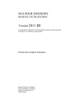
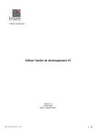
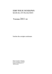
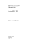
LCD Projector
Lens Replacement Procedure
Model Number
LNS-T10/LNS-W10
Notes on Lens Replacement
Lens replacement should be performed by the qualified service
personnel.
It should be followed by this procedure precisely.
Before an attempt to replace the lens, confirm the model number
(both the LCD projector and the lens) and prepare the proper lens.
The lens cover is on the lens for protection. Be sure to remove the
lens cover before installation.
When installing or removing the lens, be careful not to stain,
scratch or damage the lens.
If you have any questions, contact the dealers.
Parts List
Following parts are contained in the packing.
1 piece
● LENS
1 piece (Part No. 610 301 5040)
● LIGHT-BLOCK SHEET (Spare)
Notes on Lens Replacement
After the lens replacement (before attaching the top cabinet), check the following
things.
1. Check the lens is properly installed.
2. Check no wiring is tangled on the gear of the lens motor or other mechanical
parts.
3. Check no parts is missing, or no mounting part is lost.
Printed in Japan
1AA6P1P3841-- (IDEP)
Lens Replacement Procedure
Perform the steps 1-6 for lens replacement.
First set the lens at the highest position with lens shift adjustment.
1
Remove the Lens Cover and the Top Cabinet
1. Turn the Lens Cover counter-clockwise and pull it
toward front to remove the Lens Cover.
2. Remove the two screws (SCREW "A") and remove
the Top Cabinet.
TOP CABINET
LENS COVER
1. Pull Lens Cover toward front and remove it.
2. Remove the two screws (SCREW "A") and remove
the Top Cabinet.
TOP CABINET
LENS COVER
2
SCREW "A"
Fig-1-1
SCREW "A"
Fig-1-2
Remove the Light-Block Sheet Base
Slide the Light-Block Sheet Base upward to remove it.
LIGHT-BLOCK
SHEET BASE
Fig-2
-2-
3
Remove the Lens
Push the Lens Lock Lever and turn the lens counterclockwise (1/4 turn) and then take it out.
Be careful not to drop the lens.
LENS LOCK
LEVER
Fig-3
4
Mount the Lens
1. Remove the protective caps (front and back) on the
lens.
2. Put the Light-Block Sheet through the lens.
3. Insert the lens into the Lens Bracket of the projector
as matching the mark on the lens to that on the
Lens Bracket.
4. Turn the lens clockwise until the lens is locked with
Lens Lock Lever.
LENS
BRACKET
Insert the lens into the Lens Bracket
as matching these marks.
Fig-4
-3-
5
Mount the Light-Block Sheet Base
Mount the Light-Block Sheet Base.
LIGHT-BLOCK
SHEET BASE
HOOKS
LIGHT-BLOCK
SHEET
Light-Block Sheet should be
located under the hooks.
Fig-5
HOOKS
6
Mount the Top Cabinet and the Lens Cover
For the Cabinet Fig. 6-1
1. Mount the Top Cabinet with 2 screws.
2. Mount the Lens Cover.
Position the mark "UP" of the Lens Cover on top and
push into the cabinet. Turn the Lens Cover
clockwise until it is securely locked.
For the Cabinet Fig. 6-2
1. Mount the top cabinet with 2 screws.
2. Push into the Lens Cover to the Top Cabinet.
Confirm the top and bottom of the lens cover.
The part circled in Fig-6-2 should be fitted.
UP
Fig-6-1
Turn the projector on and check Lens shift, Zoom and
Focus is operating properly.
If Light-Block Sheet interfere with those operations,
check if the Light-Block Sheet is set properly.
Fig-6-2
-4-
1AA6P1P3841-- (IDEP)
1
2
-2-
3
4
-3-
5
6
UP
-4-