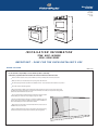
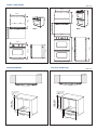
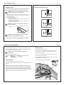
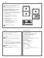
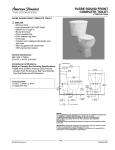
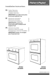
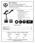
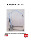
1
New Zealand
Australia
PAGE 1 OF 8
P/N 545854C
DATE OF ISSUE
11 / 2003
INSTALLATION INFORMATION
TITAN BUILT - IN OVENS
OS301 / OD301 SERIES
I M P O R TA N T - S AV E F O R T H E O V E N I N S TA L L E R ’ S U S E
BEFORE YOU START
PAGE 2 OF 8
It is the customers responsibility to ensure that the product is electrically
connected by a qualified electrical installer and conforms with all local electrical codes.
Failure to install the product correctly could invalidate any warranty or liability claims and lead to prosecution.
Make sure that the oven is located away from any strong and/or hot drafts of air.
The cabinet opening dimensions specified are the absolute minimum. These dimensions allow a clearance of up to 6mm.
The product must be electrically grounded.
We recommend that the outlet for the electrical supply cable is located in the right rear corner of the cabinet cavity.
This allows the electrical supply cable to sit inside the rear chamfered corner of the oven and prevents it being jammed
between the cabinet wall and the rear of the oven.
The oven support surface should be flat, level and be able to support a weight of
at least (190 Kg) for a double oven and (108 Kg) for single oven models.
You will need a No.2 Phillips screwdriver to complete the installation of the oven
into the cabinet. There should be 4 suitable wood screws with this installation kit
(Part number 556075) and 4 spacers (Part number 545455).
Allow at least 1.5m free length of connection cable within the cavity for ease of
installation and service of the oven.
Ensure a suitable disconnection switch is incorporated in the permanent wiring,
mounted and positioned to comply with the local wiring rules and regulations.
Outlet for
electrical supply
PRODUCT DIMENSIONS
PAGE 3 OF 8
718mm
Oven Door 550mm
Ove n Door 550mm
570mm
570mm
718mm
OS301
OD301
757mm
1217mm
688mm
675mm
1230mm
757mm
RECESSED DIMENSIONS
PROUD DIMENSIONS
PAGE 4 OF 8
TOP VIEW
TOP VIEW
693mm - Single
1235mm - Double
Recess Height
681mm - Single
1222mm - Double
Inside Cabinet Height
m
t
5m de ne
57 Insi abi epth
C D
724m
Cabin m Inside
et Wid
th
681mm - Single
1222mm - Double
Inside Cabinet Height
Minimum Distance
Under Benchtop
for Single ovens
70mm
Minimum Distance
Under Benchtop
for Single
70mm
m
t
5m de ne
59 Insi abi epth
C D
20mm
Reces
s
724m
Cabin m Inside
et Wid
th
762mm
Reces
s
Width
PREPARING THE OVEN
PAGE 5 OF 8
UNPACKING THE OVEN
FLUSH FITTING INSTALLATION OPTIONS
Do not use door handles or any part of the control panel for lifting the product.
Before the product is lifted, the oven doors and racks are to be removed.
a
WARNING : Extreme care is to be taken when lifting the product as it
is very heavy. Failure to do so may result in injury.
20 mm
1. Carefully lay the product on its back. Remove the external wrapping and the
bottom polystyrene protector and pallet. Stand the product up and remove all
other polystyrene packaging.
2. Remove the oven doors. This is done by:
Open the oven door fully.
Lift the catches on both of the hinges over towards you onto the hooks
of the hinge arm (see picture below).
Raise the door slightly, holding on either side near the handle, making
sure that the clips stay on the hooks.
2.5 mm
b
20 mm
WARNING : Do not lift the door out by the handle as this may cause
damage to the product.
2.5 mm
Lift the door out.
CUPBOARD FRONT
Door Hinge
Hook
c
Clip
Door
20 mm
WARNING : Do not disengage the hinge hooks when the door has
been removed as they are differcult to re-engage.
2.5 mm
DRAWER FRONT
3. Remove the wire shelves and oven trays by sliding them out. Use both hands
to remove each item. Remove the cardboard packaging from the oven cavity.
ELECTRICAL REQUIREMENTS
PAGE 6 OF 8
The electrical voltage and frequency that is correct for this oven is stated on the serial
number plate located inside the top vent. It is the customer responsibility to ensure that
this oven is connected to the correct electrical supply.
WARNING : The oven must be connected to a permanent and
grounded supply.
Maximum current draw and Maximum Load:
Double :
Single :
240V
38.2 A 9.2 kW
21 A 5.1 kW
220V
35 A 7.7 kW
19.5 A 4.3 kW
WIRING REQUIREMENTS
A circuit breaker appropriate for the product is recommended.
WIRING INSTRUCTIONS
1. Remove the top panel from the product.
2. Feed the oven electrical supply cable through the grommeted hole on the
45o corner at the rear of the product. Then thread that cable through the
burst hole and the wiring clamp.
3. Connect the electrical supply cable to the earth post and mains terminal
block as indicated on the diagram below.
It is recommended to use an appropriate terminal lug to connect the cable to
the mains terminal block and earth post.
4. Secure the wiring clamp and re-fit the top panel.
The electrical supply conduit must be securely clamped in the cable clamp located inside
the product.
Do ensure a suitable disconnection switch is incorporated in the permanent wiring,
positioned to comply with the local wiring rules and regulations. A means of disconnection
with at least a 3mm air gap contact separation in all poles must be incorporated into the
fixed wiring in accordance with the wiring rules, unless the local wiring rules allow for the
following variation. A means of disconnection from the supply having an air gap separation
in all active (phase) conductors must be incorporated in to the fixed wiring.
wiring clamp
ATTACHMENT
PAGE 7 OF 8
WARNING : Extreme care is to be taken when lifting the product as it
is very heavy. Failure to do so may result in injury.
1. Slide the product into the oven cabinet, pushing the product between the two
oven cavities or by the edges of the oven cavity.
If the product does not sit flush with the front of the oven cabinet, make
certain that the electrical supply cable has not jammed behind the product.
Ensure the bottom vent is not blocked off or damaged.
screw
screw
screw
2. Securely fasten the oven to the cabinet using the screws provided. Insert the
screws through the holes in the side extrusions and through the spacers placed
between the side extrusion and the kitchen joinery (see diagram opposite).
Do not over tighten screws.
3. Replace the oven trays and wire shelves. The shelves have a
front and back. Insert them into the oven in the correct way to
ensure that the ‘stop-lock’ feature of the shelf works correctly
(see diagram opposite).
4. Refit the oven doors. This is done by:
Place both upper hinge arms in the top slots and both lower
hinge arms in the lower slots.
Push the hinges as far as they will go until the slot in the lower
arm locates in the hinge support.
Lower the door gently. Push the catches away from you off the
hooks. Make sure that they disengage properly.
Raise the door slightly and ensure the catches are released from
the hooks. The door can now be closed.
WARNING : Do not stand or sit on the doors.
CHECKLIST
TROUBLE SHOOTING
PAGE 8 OF 8
1. Make sure product is level and securely fitted to the cabinetry and
both oven doors open and close freely.
2. Make sure all the internal packaging has been removed from the oven cavity.
3. Make sure all oven vents and openings are clear and are free of any obstruction.
WARNING :
Failure to do so may result in a fire or poor product performance.
IF THE OVEN DOES NOT OPERATE:
Check that the circuit breaker has not tripped or the fuse blown.
Ensure that the electrical connections have been correctly made.
Ensure that power is being supplied to the oven.
Ensure the voltage is correct across all phases.
Ensure the clock has been set.
IF YOU NEED ASSISTANCE:
If a fault occurs consult the Problem Solver Section of your User Guide book.
Call your local Customer Care representative:
4. Turn the power to the oven on. The clock should light up and blink 12:00pm.
5. Set the clock to the current time.
6. Turn the oven function switch to ‘Bake’ and the oven temp switch to 200oC. Air
should blow out of the vent at the bottom of the oven. Inside the oven cavity all three
oven lights should come on. After 5 minutes open the oven door and the air inside
should feel warm. The top element should be glowing red and the bottom surface of
the oven cavity should feel warm to lightly touch.
WARNING :
Do not touch the top element as this may result in injury.
7. Turn both the oven function switch and oven temp switch back to off and repeat
for the other oven if product is a double.
FOR NEW ZEALAND
P.O. Box 58732, Greenmount, Auckland.
Toll Free 0800 FP CARE (0800 37 2273)
Fax
09 273 0656
Email
[email protected]
FOR AUSTRALIA
P.O. Box 798, Cleveland, QLD 4163.
Toll Free 1300 650 590
Tel
07 3826 9100
Fax
07 3826 9298
Email
[email protected]
Please have the model and serial number of your product ready for the
Customer Care representative.