1
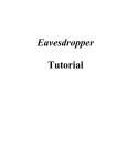
GS M s in gle / du al c h an n e l gat e way s
US ER S MANUAL
WINNER, GSM 850/1900 MHz, 900 /1800 MHz, 800/1900 MHz
SIM cards and Wavecom Module embedded
Single/ double Fixed Cellular Gateway Units
VERSION V5
Last updated:
04/04/04
Dear Customer:
Thank you for purchasing one of our WINNER GSM single/ dual channel gateway
units.
The information in this manual does not constitute a warranty of performance,
although the information has been compiled and checked for accuracy by Eurotech
Communication Ltd. All our products are developed and produced by an experienced
staff, who aspire to achieve customer satisfaction, utility value, quality and
reliability of products.
Eurotech Communication Ltd reserves the right to update this publication without
notice.
Trademarks:
EUROTECH is a registered trademark.
Warranty policy:
The WINNER GSM gateway product you have purchased is under warranty for 1 year
from the date of purchase by original purchaser. In case of defects in materials or
workmanship Eurotech Communication Ltd. will replace free of charge. This warranty
applies to hardware/ software and does not include SIM cards.
This warranty will not be honored if the device has been mishandled in any way.
Approvals:
The WINNER GSM gateway products are approved for connection to all
telecommunications services via a PBX, telephone line or even a personal extension.
ISO 9001: 2000 approved, they also feature a modern user-friendly design, provide
maximum control and economy of operation and aid in radiation prevention.
Address:
Eurotech Communication Ltd,
P.O.Box 621, Industrial park Z.H.R Rosh-Pinna 12000
Tel: 972-4 -6801080
Fax: 972-4 -6801081
www.eurotech-communication.com
TABLE OF CONTENTS
OVERVIEW
4
Packing List
Safety guidelines
General Information
Interference with Medical and Personal Electronic Devices
6
Antenna Considerations
6
Installation Steps and Procedures
6
STAGE 1: Identifying potential sources of interference
STAGE 2: Assessing the subscriber site
STAGE 3: Testing the location for signal strength
STAGE 4: Installing the system
STAGE 5: Programming of SIM cards
STAGE 6: Testing prior to departing site
6
7
7
4
8
10
General Technical Information
11
Telephone characteristics
11
Overview
Th is u s er s m a n u a l will h elp you b es t in s t a ll you r WINNE R GS M ga t ewa y u n it , a n d
provide you with the basic guidelines for handling any problems that might arise.
In general, the WINNER GSM single/dual gateways provide a flexible and cost efficient
connection between your telephone system and the GSM mobile networks. In essence
the device acts as a router that is programmed to choose the Least Cost Route when you
make a call from your PSTN line to a cellular phone. The GSM gateway connects to a
trunk line and bypasses the telephone company thus significantly reducing overhead
costs of telephone calls.
Connect to your PBX or landline phone or even to a specific phone extension (special
order), and you will save money on all calls by bypassing the telephone network and
obtaining direct access to the GSM networks.
The embedded 'Wismo Quik' Wavecom Module and SIM cards which act as 'Smart' user
Id cards that encrypt voice and data transmissions and store data about the specific
user and personal phone settings, together make the GSM gateway a cell phone in itself.
The WINNER gateways are therefore an essential tool for cutting overhead costs of
telephone bills as they allows direct access to the GSM networks and cuts costs of
airtime and interconnections.
The WINNER GSM gateways are intended for middle to large enterprises but can be
installed on regular phone lines in your home or home office.
There are certain features that may be relevant to the product you have selected
and some that are not. At any rate all are discussed in the following manual.
The WINNER GSM single/ dual channel units, when used with the appropriate telephone
equipment (antenna, adapter, SIM cards, telephone PSTN line or PBX) will function as an
ordinary landline and support the following features:
Cost-saving routing of incoming calls
'Follow Me' call forwarder to your personal mobile
GSM and PSTN interconnection via internal LCR
Caller ID, LCD, RTC
Fax, Data, SMS Transmission Optional
Internal Battery Backup Optional
FXO/ FXS interface
Polarity Reverse
Outstanding voice performance and echo cancellation
The WINNER - GSM Dual Channel Gateway unit: Main features and Benefits
o
Can use up to SIMs (up to four SIM cards per GSM channel enabling two
outgoing simultaneous calls to any four operators
Packing list:
When you receive your WINNER device please inspect the package to verify that you have
the following:
1 . One WINNER GSM single/ dual channel gateway unit
2 . Adapter
3 . Antenna
4 . RJ-11 cable
5 . User's manual
6 . Guarantee
Safety Guidelines:
For the safe and efficient operation of your WINNER gateway unit, please observe the
following guidelines:
Please read the installation instructions and safety guidelines in this user's
manual carefully before installing the unit
Do not handle the equipment before disconnecting it from the electrical outlet
Do not use any cleaning agents or detergents on the exterior or interior surfaces.
If you intend to clean the device, disconnect from electrical outlet and use only a
damp cloth
Do not position device in a damp place; do not expose to water
Do not expose to extreme temperatures: optimal operating temperatures
-5° C to + 50°C.
Position equipment in a stable environment; any sudden fall or sharp movement
may damage the device
Do not cover or stick any foreign objects in devices' openings or ventilation holes
Do not operate your WINNER device while any person is within 0.02m of the
antenna. A person or object within 0.02 m of the antenna could impair call quality
and may cause the phone to operate at a higher power level than necessary.
Warning: Potentially Explosive Atmospheres:
Do not operate your WINNER near blasting caps, or in a blasting area, to avoid the
possibility of triggering an explosion
Do not operate a WINNER transmitter in a hazardous atmosphere: an explosion or
fire may result
The telephone interface is not designed for outdoor application:
RJ-11 cable must not be run to an outdoor telephone; this minimizes equipment
exposure to coupling and directs lightning surges.
General user information:
Placement of the device: the WINNER GSM gateway unit is designed for installation on
a vertical surface but may be mounted also on a wall.
If you wish to mount the device on a wall follow these steps:
1. Remove the black metallic strip used for hanging the unit on the wall by sliding it out
from the back of the WINNER unit
2. Place the metallic strip on the wall to indicate the location of the screws
3. Hold the strip on the wall and drill wholes for the screws to go into the wall through
the metallic strip
4. Place the unit onto the wall by sliding the metallic strip back into its place.
Interference to Medical and Personal Electronic Devices
Most electronic equipment is shielded from RF energy. Nevertheless, RF energy from the
WINNER transmitter may affect inadequately shielded electronic equipment. We
therefore advise to consult the manufacturer(s) of your medical and personal electronic
device(s), (for example a pacemaker or hearing aid) to determine if they are adequately
shielded from external RF energy.
Do not install a WINNER gateway unit in a health care facility, if regulations posted in
the area restrict the use of cellular phones. Hospitals and health care facilities may be
using equipment that is sensitive to external RF energy.
Antenna Considerations:
Use only the supplied or approved antenna. An unauthorized antenna, modifications or
attachments could affect call quality.
Installation STAGES and Procedures
The installation procedure consists of the following steps:
STAGE 1: Identifying potential sources of interference
STAGE 2: Assessing the subscriber site
STAGE 3: Testing the location for signal strength
STAGE 4: Installing the system please note differences in single/ dual channel units
STAGE 5: Programming of SIM cards
STAGE 6: Testing prior to departing site.
STAGE 1 - Identifying potential sources of interference
The electronic circuitry of some telephones may be insufficiently shielded to operate
properly with the WINNER gateway units. When making or receiving a phone call, if your
h ea r a h u m m in g s ou n d or n ois e in t h e ea r p iece of t h e t elep h on e con n ect ed t o t h e
WINNER, or if any other party hears the hum or noise, move the telephone away from
the WINNER. If moving it farther away has no effect, try using a different telephone.
The WINNER is a two-way radio and as such, some occasional interference is
unavoidable. For best results, choose an electrical outlet away from obstructions. Do
n ot place the WINNER near items which may increase static, such as:
Electrical appliances
Lamps
Microwaves
TVs
Fax Machines 4 Feet (1.2 meters)
Computers 4 Feet (1.2 meters)
Refrigerator
Vacuum cleaner
Light dimmers
Fluorescent bulbs
Motors
Fans
STAGE 2 : Assessing the Subscriber Site
i.
ii.
iii.
iv.
v.
vi.
The WINNER GSM gateway must be installed indoors:
Basement installation is not recommended, it can be done, but you must
use an external antenna
Installation in a place in which the temperatures may not exceed the
specified operating temperature range (see safety guidelines above)
You should make sure that there is sufficient air movement
Installation in higher locations is preferred i.e. near windows and outer
walls
STAGE 3: Installing the system:
1)
Inspect the package, you should see: a unit gateway, an antenna, an adapter, a
user's manual. Please note: the WINNER unit comes without the SIM card(s)!
2)
Connect the antenna at a distance greater than 1 meter from the unit. Location of
the antenna is important in order to get best performances, thus once you turn the
power on, make sure you have best reception and clear conversation with the
unit.
3)
Insert SIM card into the unit:
A)
In case of single channel unit, insert the SIM card in the designated slot (on
the right side panel) adjacent to the antenna connection you will see a thin
mettalic black colored drawer. Use a small pointed object such as the point of a
ballpoint pen into the little hole on the right side of that drawer/slot to open the
drawer, then insert the SIM into that drawer (SIM face up) and close the drawer
firmly.
In case of dual channel unit, there are up to four SIM card slots on the bottom side of
the unit for each module. The SIM card slots are numbered from the top down as #1,
#2, #3 and #4.
Insert SIM #1 for the first Provider, this is the default provider, the main provider.
Insert SIM #2 for the Second Provider.
Insert SIM #3 for the Third Provider
Insert SIM #4 for the Forth provider
For 'Up to 8' SIM cards 1- 4 for each module place each according to provider (no.1 to 4)
as described above.
4)
5)
6)
7)
8)
Connect the gateway unit to a PBX telephone network or telephone line with the
RJ-11 cable (provided with unit) on the left side panel.
On the left side panel you will find the POWER socket. Connect the adapter
(provided with unit) to the electrical outlet and then to the electrical socket.
Note: The power input is 90 260 VAC and the output is 12 VDC 1.2 Amp
Wait 30 seconds for the unit to startup.
Connect a landline ordinary telephone to the RJ-11 connector (pin 3 and 4 are
used for Tip and Ring)
In case of WINNER GSM single channel unit: place an outgoing call to test the
system. If the LCD shows the number you have dialled; the device is in correct
operation mode OK. If you see the operator/ provider name on the LCD try to
make an outgoing call. You should see the number dialed on the LCD, then make
a call into the unit from another telephone, cellular or landline, you should see the
ID caller on the LCD.
In case of dual channel unit (2 to 4 SIM) the following information and programming
steps are relevant:
Once you connect the power adaptor to the connector (next to the RJ-11 connector) the
unit should power up and the LCD should show the first #1 Operator/ Provider name
after initialization.
Note: please wait for about 30 seconds to power up!
Stage 4 Programming of SIM cards WINNER GSM Dual channel up to 8 SIMs:
For cases where you use more than 1 SIM only!
Otherwise skip the following; you are finished and can now use your WINNER GSM
single channel unit.
Now the unit is working, we need to verify that each prefix is setup according to the
correct SIM.
First, connect a landline phone to the RJ-11 cable of the particular channel you want to
test the device.
On the V-8002 / D1 or D2, each channel has it own RJ-11
To start programming the WINNER you need to pick up the handset of the landline
phone and press the star key 3 times " * * * ".
LCD should indicate "Programming Mode" ( it is now in programming mode).
In order to scroll through "Programming Mode" menu press "#".
To enter the sub menu press "*".
1. Adding or editing the SIM Prefixes:
Step 1: Pick up the handset of the landline phone and press " * * * ", LCD should
indicate "Programming Mode".
Step 2: After 1 second LCD should show "1. SIM Prefixes", press "*" to get into the sub
menu, LCD will indicate "Select SIM#1".
To s cr oll b et ween t h e S IM s p r es s "# ". For ch oos in g t h e S IM you wis h t o a d d
prefixes press "*".
Step 3: If there are not any prefixes the LCD will indicate "SIM#3 is empty" and after 1
second the LCD will indicate:
"ADD? *-yes, #-no".
If there are prefixes programmed, (for example: SIM number 3) the LCD will indicate
"SIM#3: Prefix , you ca n view a ll t h e p r efixes b y p r es s in g t h e p ou n d k ey # .
Step 4: At the end of the prefixes LCD will indicate "ADD? *-yes, #-no".
To add new prefix press "*" the LCD will indicate "Add SIM#3:", press your prefix and "*"
t o in p u t . LCD will in d ica t e (a ga in ) Ad d S IM# 3 : if you wis h t o in s er t a n ot h er p r efix
press your prefix, if you do not wish to insert press "*" again.
Returning to the main menu press "#" until LCD will indicate "1. SIM Prefixes".
2. CLEARING Prefixes: Allow you to delete all prefixes in any specific SIM:
Step 1: Pick up the handset of the landline phone and press " * * * ", LCD will indicate
"Programming Mode"
Step 2: After 1 second LCD will display "1. SIM Prefixes", press "#" until LCD will
indicate "2. CLEAR Prefixes"
Step 3: press "*" to roll into the sub menu. The LCD will indicate "Select SIM#1".
To s cr oll b et ween t h e S IM s p r es s "# ", For choosing the SIM card whose prefixes you
wish to delete press "*".
For example: SIM number 3 LCD indicates "SIM#3 is empty", after 1 second the LCD
will indicate "2. CLEAR Prefixes".
All The prefixes which were inserted in the specific SIM will be deleted automatically.
3. AnsSuperVision: To change the voltage on line:
Step 1: Pick up the handset of the landline phone and press " * * * ".
LCD will indicate "Programming Mode". After 1 second LCD will display
"1. SIM Prefixes", press "#" until LCD will indicate "3. AnsSuperVision".
Step 2: Press "*" to roll into the sub menu, the LCD will indicate "# - Choose / * - Save".
After 1 second LCD show "Disable", To scroll between options in the sub menu
press "#", to choose press "*".
4. AnsSprVisTimer: To change the Timer:
Step 1: Pick up the handset of the landline phone and press " * * * ",
LCD will indicate "Programming Mode". After 1 second LCD will display "1. SIM Prefixes",
press "#" until LCD will indicate "4. AnsSprVisTimer"
Step 2: press "*" to scroll into the sub menu, the LCD will indicate
"# - Change / * - Exit". After 1 second the LCD will display "100msX01", to change the
value press "#", LCD show "0-9 Edit / * - Exit".
If you want to edit press 0 9 (digits on phone need t o con s is t of 2 d igit s ), if you d on t
press "*" to exit.
5. Min Digits: Allow you to control in which form the call will be transmited (Minimum
COUNTER):
Step 1: Pick up the handset of the landline phone and press " * * * ",
LCD will indicate "Programming Mode". After 1 second LCD show "1. SIM Prefixes ",
press "#" until LCD will indicate "5. Min Digits"
Step 2: press "*" to roll into the sub menu, the LCD will indicate "# - Change / * - Exit".
After 1 second LCD show "Min: 07", to choose press "#",
LCD will display "Min: (02-08) ".
Step 3: Ch oos e d igit b et ween 0 2 t o 0 8 (d igit on p h on e h a ve t o b e 2 d igit s ), if you d on t
press "*" to exit.
6. Max Digits: Allow you to control in which form the call will be transmitted (Maximum
COUNTER):
Step 1: Pick up the handset of the landline phone and press " * * * ",
LCD will indicate "Programming Mode".
After 1 second LCD will display "1. SIM Prefixes", press "#" until LCD will indicate
"6 . Ma x Digit s
Step 2: Press "*" to roll into the sub menu, the LCD will indicate "# - Change / * - Exit".
After 1 second LCD will display "Max: 09 ". To choose press "#".
Step 3: LCD will indicate "Max:
(05-20)", you have to choose digit between 05 to 20
(d igit on p h on e h a ve t o b e 2 d igit s ), if you d on t p r es s , "*" to exit.
7. InterDigit tmr: Allow you to control in which form the call will be transmited (By
TIMER):
Step 1: Pick up the handset of the landline phone and press " * * * ".
LCD will indicate "Programming Mode".
After 1 second LCD will indicate "1. SIM Prefixes", press "#" until LCD indicates
"7. InterDigit tmr"
Step 2: Press "*" to scroll into the sub menu, the LCD will indicate:
"# - Change / * - E xit . Aft er 1 s econ d LCD will d is p la y "5 0 m s X2 0 0 ", t o ch oos e p r es s
"#", LCD will display "50msX (001-200)", you have to choose digit between 001 to 200
(d igit on p h on e h a ve t o b e 3 d igit s ), if you d on t p r es s "*" t o exit .
8. IgnoreFirstDig: Allows you to choose first digit to ignore:
Step 1: Pick up the handset of the landline phone and press " * * *",
LCD will indicate "Programming Mode". After 1 second LCD will display "1. SIM Prefixes",
press "#" until LCD indicates "8. IgnoreFirstDig".
Step 2: Press "*" to roll into the sub menu, the LCD will indicate "# - Change / * - Exit".
After 1 second LCD will indicate "Digit: ". To choose digit press "#" until LCD displays the
digit that you need and press "*" to choose.
9. S/W Version : Indicates the Software version.
10. Data Mode : Must be off when being used for 'Voice' only.
11. Pre_Dialling: Allows you to write string that will be transmitted with number phone:
Step 1: Pick up the handset of the landline phone and press " * * * ".
LCD will indicate "Programming Mode". After 1 second LCD show "1. SIM Prefixes", press
"#" until LCD will indicate "11. Pre_Dialling"
Step 2: Press "*" to roll into the sub menu, the LCD will indicate "# - Change / * - Exit".
After 1 second LCD show "String: ", press "#" write your string and press long "*",
(until LCD will indicate "11. Pre_Dialling" .
12. Setup CID : The option to block the Caller I.D in your gateway (will not show the
caller number on your LCD).
STEP 6: Testing prior to departing site.
In case of more than 1 SIM: make calls to each provider and see the call progress on the
LCD, You s h ou ld s ee Pr ovid er s a n d t h e d ia led n u m b er , if a ll wor k s 'OK' t h en you a r e
done.
General technical information
Electrical
Power supply: 12 VDC +/- 5% 1,2 A
720 mA average in GSM 900 at Tx power max 2W
920 mA average in GSM/GRPS 900 at Tx power max 2W
100 mA in idle mode
Physical
Absolute maximum dimension: 165 x 127 x 30 mm
Weight: 600 g
Casing: Complete shielding-stainless steel
Mounting: 4 screw holes
Operating temperature range: -5°C to + 55°C
Optimal storage temperature: -35°C to +85°C
Analog Telephone/Analog PBX interface
Tip/Ring Voltage 48V
Line current
25ma
Ringing
Voltage 140
Vpp
Load 3REN
Crest Factor 1.25
Frequency
20 Hz
Cadency
2s/4s
Answer supervision - Reverse polarity
DTMF compliancy
Dial Tone 400 Hz
Busy Tone 400 Hz, cadency 500ms/500ms
GSM circuit Data Features
Data circuit asynchronous, transparent and non transparent up to 14,400 b/s
Automatic fax group 3 (Class 1 & 2)
Alternate speech and fax
MNP2, V.42bis
Telephone Line Characteristics
DC Characteristics
Ringing Voltage:
On hook voltage:
Off hook Voltage:
Off hook Loop current:
Input Impedance:
-70 V DC typical
-58 V DC typical
-24 V DC typical
27mA @ 600 Ohm programming resistive
480 Ohms to 720 Ohms, 600 ohm typical
DTMF Dialing:
Detection level:
On time:
Off time:
-25dBm to +3dBm
50msec.
12 characters
Ringing Signal:
Feeding type:
Distortion:
Ring drive capability
Minimum ring Voltage:
Frequency:
Normal dialing tone:
Frequency:
Level:
Cadence:
Congestion / Busy Tone:
Frequency:
Level: 2dB
Cadence:
500ms 20% pause
Balanced signal
Less than 5%
3 type A
40 Vrms crest factor 1.2
(20 Hz )
400Hz
2dB
400Hz
500ms 20% signal
Enviromental characteristics
Compliance:
The WINNER complies to the following requirements:
Tem p era tu re
We claim -5° to 70° (Israeli Standard Institute Approval is in process).
Hu m id ity
5% to 95%
Safety
(Testing at Israeli Standard Institute Approval is in process)
Packing
Per EuroTech standard
Transportation
Transport conditions are according to EuroTech Standards.
Storage Condition
Storage conditions are according to class 1.1, ETS 300 019 1 -1 (-20°C +80°C)
-25°C to +65°C
Mounting
Wall Mounting
In case you wish to mount on wall see instructions above in General Information.
configuration the WINNER attached to the wall with one screw.
Desk Top Mount
In desk top mounting configuration on four rubber standoffs, it should be mounted
at least .5 meter from the telephone set.
Packing
Each WINNER package contains:
One WINNER unit, metal box.
One Omni antenna or an external antenna (optional)
This booklet which includes a user manual.
Labels
Each WINNER labeled as the following :
Product ID: located at the box side( in future units).
The label contains product model number, Serial number, Date and code identified
as WWYY
(1 s t t wo d igit s id en t ify t h e ch r on ologica l week in t h e yea r , 2 nd tow digits identify the
year), Hardware and Software
version.
For Example: Logo, Model No, Serial No, Rev.
HardwareX/SoftwareY:0X/0Y , Date: onth/Year
Manufacturing
At EuroTech Communication we bear in mind at all times manufacturing at high
Quality and cost effective are the
most significant considerations in the design for Manufacturing of the WINNER.
Shipment
All goods will be sold FOB, customer will pay for delivery from factory.
Customer will advise on the way the products will be shipped.
Customer will take care of shipment including all necessary payments for
insurance, delivery, custom, etc. as FOB requires.
Reliability
The WINNER Field Quality goal is and will be determined by reliability prediction
and actual ALT results.
Our target is:
0.5-1.0% per month, This goal is susceptible to changes.